v8kid
|
| posted on 13/3/11 at 05:37 PM |

|
|
Lots of decisions made.
Firstly loadings. Seems that I was not too far away in my guess a loading of 2g lateral (cornering) 2g (braking) and 3g bump is the accepted loadings
used by manufacturers. I hasten to add this info is gleaned off internet postings and as such cannot be considered pucca but they seem reasonable to
me. Also a factor of safety of 3 before yield ( deformation that does not return when the load is removed) is the norm. Fairly chuffed my guesses were
inthe right ballpark.
So lateral and braking load is 300x2g = 600kgf. I won't bother working in mass and newtons (to the physicists horror!) if you don't mind as
its simpler. Bump load will be 900kgf.
Intention is to go straight up to load of 600kgf and gradually increase up to minimum safe load of 1800kgf. I think I'll take some measurements
of deformation as I go but thats that the general plan. After that gradually increase until it breaks!
It's difficult for one person to watch for deformation and read the scale at the same time but I'll just take a bit longer
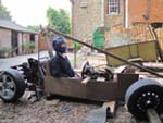
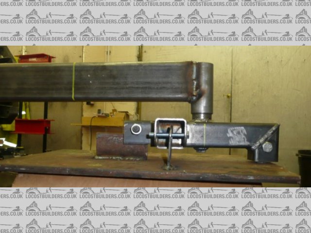
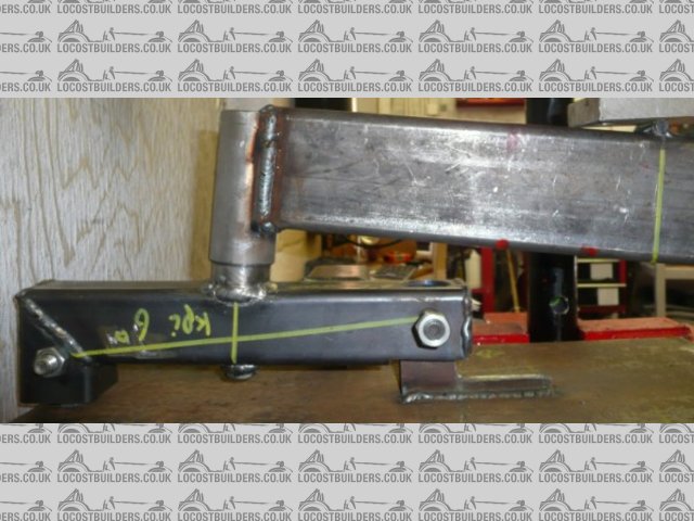
So here is the upright on the press
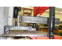 
upright on press
The upper ball joint, or 0.5" rod end in my case is on the right and is bolted through the 0.5" plate. The upright is free to rotate in 3
degrees of freedom. The bottom ball joint is replaced with a roller bearing on a bit of 0.5" plate. I'll grease it when testing. This avoids
putting the upright in compression. This upright is drilled for 6 deg kpi and the yellow horizontal(ish) line indicates this. as you can see the
design easily gives you a good range of kpi's if that is your thing.
The horizontal bar welded to the dummy stub axle has a yellow line marked at the dia of my wheels which is 535mm. I think I will weld a bit of round
bar on here to make sure the load is applied exactly at this point. Note the reinforced press crossbar! The pin goes all the way through by the
way.
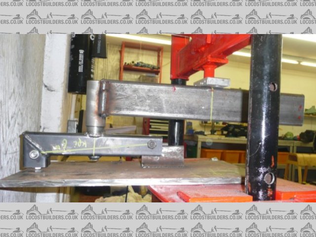
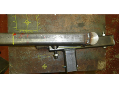
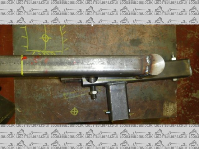
Next pic is the other side and shows the steering arm. the restraint will be in tension due to the effect of the caster angle
upright on jij
The hole in the restraining strap is oversise so as not to restrict movement which should be freeish in a flat plane and I din't think it will
materially effect the outturn. It should be two rod ends back to back but the force is low here or track rod ends would get wasted in practice. I
think I might replace the 8mm bolt with a 0.5" bolt due to the bending load on it.
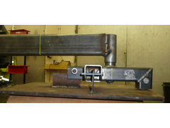
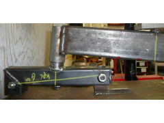
The next pic shows the castor and now its easier to see why the steering arm restraint will be in tension. The caster angle by the way is 6 deg.
The hole you can see at the back of the lower ball joint is to allow it to be mounted asc far outboard as possible. Those who are going for zero scrub
will have already discovered that the bottom ball joint needs to be 3mm from the disc - any closer and it can touch. I suspect the upright will fail
at this position
upright castor angle
So all I have to do now is wait for the new hanging scale to arrive and I can do the test.
Cheers!
You'd be surprised how quickly the sales people at B&Q try and assist you after ignoring you for the past 15 minutes when you try and start a
chainsaw
|
|
|
|
|
ettore bugatti
|
| posted on 16/3/11 at 02:48 PM |
|
|
If you want to be entirly safe, you could test a OEM upright in the same way.
|
|
|
v8kid
|
| posted on 16/3/11 at 04:28 PM |
|
|
quote:
Originally posted by ettore bugatti
If you want to be entirly safe, you could test a OEM upright in the same way.
Cracking idea anybody got one to donate?
OK well this is the last test for a bit as I will be up to my ears in other stuff until the 23 April but if anyone is interested I'll restart
after then.
So got the digital hanging scale and it made it much easier so here is the latest failure
160311fail
If you look to the left of the spindle at the upper surface of the upright the upright wall is deformed upwards. To the right it is depressed.
Interestingly the spindle itself is bent.
No other parts of the upright show any signs of deformation.
Now the load it failed at?
Disappointing at 1.22 tonnes when the target was 1.8 tonnes.
I'm not sure where to go from here, the spindle bending was a surprise but in the posts of fea analysis of other uprights that is shown as the
point of maximum stress it's just that I thought the fabricated upright would be weaker in comparison.
I have some thoughts on why but would appreciate your input first please chaps.
You'd be surprised how quickly the sales people at B&Q try and assist you after ignoring you for the past 15 minutes when you try and start a
chainsaw
|
|
|
Liam
|
| posted on 17/3/11 at 10:26 PM |
|
|
Interesting thread and nice work.
Not too surprising you got that yielding/distortion on the face of that relatively thin walled tube where all the load from that spindle is feeding
in. Think about how different the situation is in a solid cast production car item. I'd suggest you need a stiffener/spreader plate between the
tube and spindle to effectively thicken the material where the spindle loads feed in. At least the wall thickness of the tube again, if not more. That
should significantly improve your results and get you closer to your desired safety factor. Having said that, I could probably live with 2 for a car
that will not cover huge mileage without maintenance. Expecially as the failure mode isn't particularly catastrophic.
What is your dummy spindle made of? If it's just some mild steel stock turned up, and the real thing is made of something much stronger, that
might explain the bending you observed.
|
|
|
v8kid
|
| posted on 18/3/11 at 01:25 AM |
|
|
Thanks for the input Liam. To be fair Fred suggested that right at the beginning and I disregarded it due to my desire to save weight. Still proved
the point!
The dummy spindle is indeed turned mild steel stock.
My inclination is to reduce the upright from 3mm wall to 1.5 mm wall and beef it up locally with 6mm close to the spindle and 3mm at the rod ends.
Not sure how little I can get away with though.
Also there is a flaw in my test procedure in fact the FOS is aroung the 3 mark 'cos the momemt from the weight acts in the opposite
direction.
I'll post something later but just now I have got my final degree submission to hand in 5 weeks 
You'd be surprised how quickly the sales people at B&Q try and assist you after ignoring you for the past 15 minutes when you try and start a
chainsaw
|
|
|
MikeR
|
| posted on 18/3/11 at 09:33 AM |
|
|
Before you go thinning down the steel, what does it weigh now? What would it weigh if made of out 3mm but with another 3 or 6mm reinforcement?
I appreciate you're after saving weight, but i'm curious how much weight your talking about. It may be a case of saving a few grams for
not a huge benefit & reducing its safety margin.
|
|
|
hughpinder
|
| posted on 18/3/11 at 10:23 AM |
|
|
I like this thread, thanks for doing all these tests.
I was thinking of another aspect here - the tyre.
If its inflated to 20psi, A 195/50/15 would be squashed so the bottom of the tyre was flat on the road as far as the metal rim (about
18"*8" of area supporting) thats only about 1600kg (this ignores the side wall strength). I would suggest that therefore 1.6T on any wheel
is more than enough!
Also the tyre will have a manufacturs load rating. For road tyres this is usually in the range 75 -100 printed on the side of the tyre, and represents
a maximum load of 450 - 850 kg per tyre, so unless you use HGV tyres you're probably going to pop your tyres at a load of about half your test
load!
Regards
Hugh
|
|
|
tilly819
|
| posted on 18/3/11 at 05:20 PM |
|
|
quote:
Originally posted by hughpinder
I like this thread, thanks for doing all these tests.
I was thinking of another aspect here - the tyre.
If its inflated to 20psi, A 195/50/15 would be squashed so the bottom of the tyre was flat on the road as far as the metal rim (about
18"*8" of area supporting) thats only about 1600kg (this ignores the side wall strength). I would suggest that therefore 1.6T on any wheel
is more than enough!
Also the tyre will have a manufacturs load rating. For road tyres this is usually in the range 75 -100 printed on the side of the tyre, and represents
a maximum load of 450 - 850 kg per tyre, so unless you use HGV tyres you're probably going to pop your tyres at a load of about half your test
load!
Regards
Hugh
Thats a very good point hugh, havnt checked your maths but the tyres do take a hell of a lot of the load away from the suspension
tilly
F20C Haynes roadster 440 BHP/Tonne www.youtube.com/handmadeextreme
|
|
|
sebastiaan
|
| posted on 18/4/11 at 07:37 PM |
|
|
Some additional information on test loads according to Lotus F1 engineer Tony Rudd: "Stress suspension for a 3g bump on a 2g corner."
Taken from this little gem: http://www.formulastudent.de/academy/pats-corner/advice-details/article/pats-final-corner-for-2010/, in which a
lot of other interesting information can be found.
I'd say that you would need to dimension for 1.000.000 load cycles (which should equal infinite fatigue life when using mild steel) and a
"suitable" safety factor on top (between 2 and 3? What do others think?)
Could those who know add:
* The safe maximum stress for FE360 (bog standard mild steel) at 1.000.000 load cycles
* Their thoughts on a suitable safety factor (again, my guess would be between 2 and 3 using the loads suggested above)
|
|
|
blakep82
|
| posted on 18/4/11 at 07:42 PM |
|
|
you said you don't want to make it any thicker steel, as you want to save weight by making it half the thickness?
brakes and suspension are something where strength should not be sacrificed for weight IMO
anyway, instead of box, what about round tube? i think the flat parts will be the weakness in your tests so far, round tube might just help to
strengthen it all up, without having to make it any thicker, but i still wouldn't make it thinner.
haven't read the whole thread btw, so might have already been discussed. sorry if it has
[Edited on 18/4/11 by blakep82]
________________________
IVA manual link http://www.businesslink.gov.uk/bdotg/action/detail?type=RESOURCES&itemId=1081997083
don't write OT on a new thread title, you're creating the topic, everything you write is very much ON topic!
|
|
|