When I'm cranking, I see the engine doing about 120rpm for about 4 or 5 seconds, and then MS reports 0rpm even though I am continuing cranking. Any ideas what would cause this?

Still not running 
When I'm cranking, I see the engine doing about 120rpm for about 4 or 5 seconds, and then MS reports 0rpm even though I am continuing cranking.
Any ideas what would cause this?
Whilst it is my own ecu I had this problem, I guess it maybe that the engine is not making the 300 rpm required for megasquirt to go from crank to
run.
The engine runs on cranking enrichment until the plugs get too wet/ sooty and cuts out.
DARREN
is your VR sensor polarity correct ?
Ray
It's not even sparking yet, let alone staying in the startup enrichment phase and flooding. I'm getting no spark and the MS thinks the engine has stopped turning eventhough it still is.
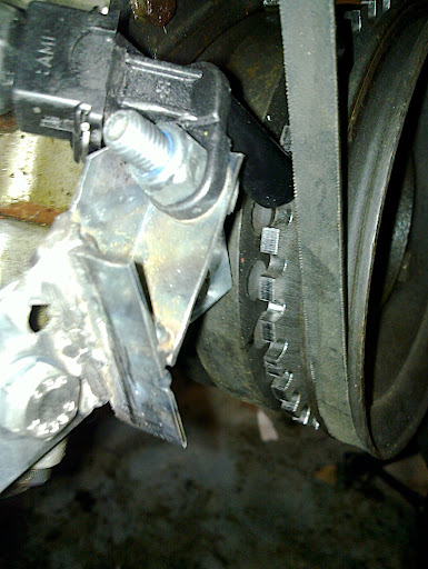
wonder if the sensor's too far away from the trigger wheel to get a decent signal, its like a little magnet inside, opening and closing as the teeth pass, i think it maybe just loses it and can't pick it up again. how close is it? it should be like 1mm away or something
no spark at all means an edis issue, so common suspects are the trigger wheel, sensor, edis wiring, edis internals, coil pack and ht leads.
Thanks for the comments so far. Done a bit more digging tonight and have found the following :-
1) Good 12v to the EDIS
2) Good 12v to the coil packs
3) Good earth on the EDIS
4) Picked loom tape apart and verified that VR sensor connected to the right wires on EDIS plug
5) Swapped polarity of VR sensor, lost cranking 120rpm signal to megasquirt
6) Swapped VR sensor wires back to how they were, still lost 120rpm signal
Don't know exact gap between sensor and trigger wheel, but it is about the thickness of two sheets of paper
does your ignition fed live to the ecu disapear under cranking? (obvious but i have seen it!)
wave a screwdriver in front of the crank sensor, and see if the MS sees a crank signal.
what material is your trigger wheel made from?
what is the gap between trigger wheel and sensor?
- colin.
quote:
Originally posted by atspeed racing
does your ignition fed live to the ecu disapear under cranking? (obvious but i have seen it!)
quote:
what material is your trigger wheel made from?

quote:
what is the gap between trigger wheel and sensor?
A bit more progress. I found a Megajolt site that had some diagnostics to carry out. On cranking the VR sensor should put out about 2.5v AC. I was seeing <1v. Looking closely at my mount, although the sensor appeared to be close enough, it wasn't sitting square to the trigger wheel. Time to make a better bracket.
While you're at it - make sure that the new bracket is really rigid, with no 'bounce'. There's a well-known symptom of misfiring
at around 4,000 rpm that's usually caused by a vibrating VR sensor.
This isn't a Megajolt issue - it's general with any symptom that uses Ford's VR sensor and EDIS.
One step forward, one step back. Welded up a new bracket (not pretty, but I'm learning) and cracked out the voltmeter. Now I get 1.2v  The
sensor is not too far away as it was actually touching the trigger wheel and has the scars to prove it. I put a washer in and the reading goes down
to 0.8v. I'm stumped.

The sensor is one of these
http://www.partsjunction.co.uk/index.php?main_page=product_info&products_id=120325
[Edited on 2/5/10 by scudderfish]
Erm what is your wheel made out of?? Stainless?? could be a problem as it is not magnetic.
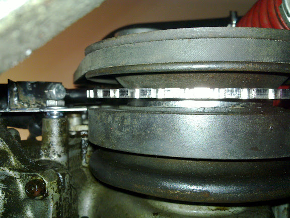
Also on second thought It LOOKS like there may not be enough room between the trigger wheel and the other pulleys. this will lead to the sensor seeing
a full steel wheel passing it and not generate the sine wave ( with the gap step where the missing tooth is).
[Edited on 2/5/10 by omega 24 v6]
quote:
Originally posted by omega 24 v6
Erm what is your wheel made out of??
Edited my post
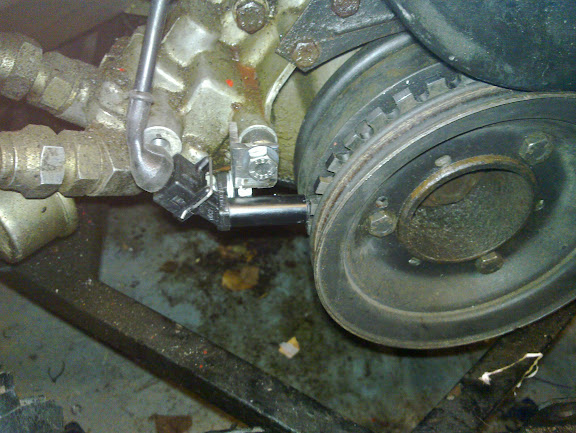
Here's another view. I'll see if I can measure the gap.

Mmm that does look a bit wider than the last piccy.
Another thought ( and it is just that so I may be being daft) But is it possible that the sensor couls be 90 degrees out??
ANYONE??????
[Edited on 2/5/10 by omega 24 v6]
The view from underneath, I think the spacing is actually fine, but it is good to eliminate possibilities.

It could be that the sensor is duff, but I'm more inclined to suspect my incompetence.
I'm getting a new sensor tomorrow, even if it's only to prove that the one I currently have is good.
Hi there,
It may be the photo, but...
It looks like your sensor isn't radial to the wheel, what I mean is, the sensor should point towards the centre of the trigger wheel. If it
isn't then it would exhibit similar symptoms to a wheel that is too far away. It also looks like it was catching at one side but not the
other.
Just a thought.
Matt
I think/hope it is distortion in the photo  When a first mounted it, it was located towards the rear of the engine, but I brought it forward. It
was this time that the sensor was in contact with the trigger wheel, and it scratched the base of the sensor across the centre and full width, which
implies the location is at least close to right.
Fair enough.
New sensor sounds like a good plan.
Matt
OK, so it isn't the sensor. The new one gives the same readings. Options now are :-
1) The mount - likely culprit and I mentally have a new design which should be better
2) Wiring - less likely, but easier to check out. The cable I'm currently using is two core screened microphone cable from Maplin.
I have a spare plug so I'll solder it up with some test leads to eliminate the cable and then crack out the angry grinder and make up a new
bracket.
It ain't the wiring, it's definitely the mount. I took the crank bolt out (always good exercise on a RV8) and slid the pulley assembly
forward. This gave me a much better view of the alignment against the crank damper, and as postulated, the sensor is not at 90 degrees to the spinney
bits. The bracket is held on by two bolts, so I removed one and rotated the bracket until the sensor was pointing in the right way. The resultant
gap is quite embarrassing  Anyway, it means I'm not at a dead end and can fiddle with something else in the hope that it will work
will be interesting to see if it is that.
My understanding was that an AC voltage wouls be produced by cutting a magnetic field with a toothed wheel Now obviously the sensor is the magnet and
a magnet has a north and south pole. I did not think it needed to be aligned to get it to work though ( although i did suggest looking at it in an
earlier post). If this does work for you it may be of great interest to oyhers on many forums who are using aftermarkey wheels and getting a poor
signal.
Well it's better, but I'm still getting <1.5v 
When I bought all my bits, I got a mount from triggerwheels, but ignored it as it clashes with the mount for my repositioned alternator. However on
reflection I may be able to use it if I chop the thickness of the mount out of a tube in the alternator mount and move the trigger wheel to the rear
of the pulley lump.
If I wasn't so incompetent, it'd be boring 
So much for that plan, I may be able to get the triggerwheels bracket in, but the sensor would not fit with the alternator in place.
Time for a rethink.
Still no joy 
I made a new, more solid, simpler mount

And I get a good 1v RMS AC out of it at the connector to the EDIS module. Still no spark. Oh well, tomorrow I'll check to see if I'm
getting a signal to the coilpacks.
Anyone have a spare EDIS8 I can borrow? 
I had a thought.
Are you connected to megatune or tuner studio.
Either way under cranking you should get an RPM reading on the guages. Is so your Vr is doing it's job if not it's where the problem is.
SPARKS!
Unfortunately I don't appear to have the RPM signal at the MS that I did in my first post.... Getting closer though  Thanks for all the
suggestions so far.
Nice work, looks like you are getting pretty close.
I guess you need to see if you are getting the "pip" output from the EDIS into the MS unit.
http://www.megamanual.com/ms2/EDIS.htm
But I guess you know that already! Outside my experience unfortunately.
Matt
Matt
I'm beginning to suspect my MS as I'm seeing a respectable signal on the PIP line (as respectable as it can be with only a multimeter anyway). I'm going to open it up tonight to see if anything has obviously let out the magic smoke.
Another random thought - how have you earthed the screening on the VR sensor's cable?
It should only be earthed at one end, to avoid 'hum loops' - if it's earthed at both ends then the screening picks up interference,
which it then radiates to the signal wires inside. If it's earthed at one end only then the loops can't happen.
In fact, ideally all of the ignition system earths should be connected to one point.
Also - I couldn't see whether anyone asked this earlier - is your sensor polarity correct? A quick search on this site should result in a neat
diagram (I'm sure that came from Flak, but don't hold me to that).
Have you got a stimulator for the MS?
I borrowed one (thanks Lars) which was excellent.
Matt
I did originally borrow a stim from MakeEverything and proved my MS was working back in November. I had a word with Phil at ExtraEFI and he said try
rapidly switching the PIP line to ground to fake an RPM signal. Tried that and not a trace of a flicker. I've posted off my MS to him to have a
look at. Looking on the bright side, I've now got a working EDIS, so I could always slap my carbs back on (!)
I think in all my fiddling I've at some point connected something to something that I shouldn't. I couldn't see anything obviously
burnt out inside it, but if there is Phil will find it.
Regards,
Dave