big_wasa
|
| posted on 13/4/14 at 07:01 PM |

|
|
"How to" OEM Focus ST170 ecu with Pats info.
"How to" OEM Focus ST170 ecu with Pats info.
WARNING I WILL NOT BE HELD RESPONSIBLE FOR ANY LOSSES OR INJURY RESULTING FROM USE OF THE INFORMATION CONTAINED WITHIN.
As this is locost builders there are some people left that love to tinker and make things.
This is to give those people that are interested in running an ST170 engine on a budget the basic wiring information. months of work this.
The key to using the ecu is the Pat's immobilizer. You must get atleast one key with chip that is matched to the ecu.
Ford 104 pin Focus ST170 2003 “ 3NFA” Pcm plug.

Missing numbers have no connection and are not used on the Pcm.
Pin number -- colour -- function.
03 white/red--IMRC pin4
09 white/black--Barometric sensor pin 3
12 black/white –IMRC pin 3
13 orange/black--DLC pin 13 modal program.
15 blue/black-- DLC pin 10 scp-.
16 grey/orange-- DLC pin2 scp+.
17 black/white – high speed fan.
19 grey/orange -- Pats TX signal.
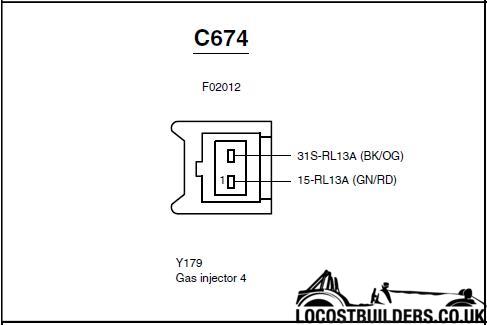
20 black/blue -- Injector 3 switched earth.
21 white/red -- crankshaft position sensor +.
22 brown/rd --crankshaft position sensor -.
24 black/yellow -- earth.
25 black/red -- earth.
26 black/orange – coil pin 1.
27 black/red -- start inhibit relay.
28 white/violet – telemetric.
31 black/yellow -- Power steering pressure switch.
32 brown/yellow—knock sensor pin 1.
35 white/red— HSO2 1 pin 4.
36 brown/blue -- MAF pin 4.
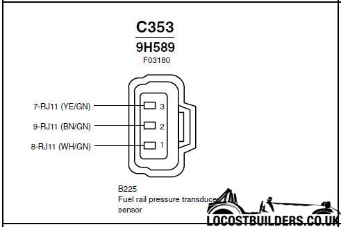
37 white/green—fuel rail pressure switch pin 1.
38 white -- coolant temp sensor pin 1.
39 white violet -- Air temp in MAF pin1.
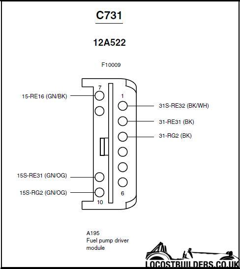
40 green/black -- fuel pump driver pin 7.
41 green/yellow -- A/C clutch pressure switch.
42 black/orange -- PATS Led.
43 white/blue –- Trip computer.
45 black/red—vvt solenoid pin 2.
46 black/green—Engine run relay
49 blue/red—DLC pin 14 can-.
50 grey/red—DLC pin 6 can+.
51 black/yellow -- earth.
52 black/green -- coil pin 3.
53 white/green -- Pats RX signal.
54 black/white -- fuel pump driver pin 1.
55 red-- KAM perm live.
56 black/blue—evap pin 2.
57 white/black—knock sensor pin 2.
58 white/blue -- Vehicle speed Sensor pin 2.
59 grey – Alternator pin 1.
60 white -- HO2S 1 signal
64 white --clutch switch.
68 black/blue – engine cooling fan.
69 black/yellow -- Ac wot relay
70 black/white -- injector 1 pin2.
71 green/yellow -- switched 12v from power relay.
72 blue—alternator pin 2.
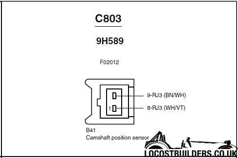
76 white/violet -- Cam position sensor pin 1.
77 black/yellow -- earth.
83 green/yellow -- idle air control valve pin 2.
85 brown/white -- camshaft position sensor pin 2.
86 white/red -- Ac high pressure switch.
88 white/blue -- MAF pin 5..
89 white -- throttle position sensor pin 2.
90 yellow -- 5v Voltage Reference (5v out from ecu)
91 brown -- sensor common brown
93 black/yellow -- HO2S 1 heater control.
95 black/orange -- injector 4 pin 2.
96 black/yellow -- injector 2 pin 2.
97 green/yellow -- switched 12v.
100 black/blue – HO2S 2 pin 2.
103 black/yellow -- earth.
The Immobilizer.
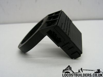
The picture below shows the transceiver or aerial. This is found behind the steering cowl. The ring sit’s around the ignition switch and is held to
the steering column with one screw.
This is the wiring plug.
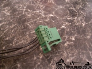
It needs cutting from the car with as much wire as can be pulled free.
Retaining clip shown at the bottom.
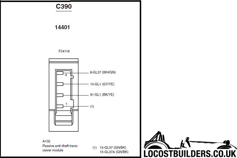
There are four pins, They may be colour coded as above or they may be all black as shown in the photo. This depends on the age of the donor.
Pats indicator. This is the led that is usually found in the clock. Its job is to show you the status of the immobilizer. Ford’s Passive Anti- Theft-
System ( PATS )
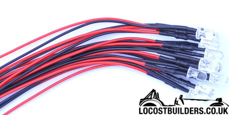
Just one Pin from the ecu plug, No 42 (black/blue). This is a switched earth. Take one Led, colour of your choice. You need one that is pre wired with
a resistor. This is mounted in your dash. The negative or black wire is connected to pin 42 of the ecu plug and the red or positive wire is connected
to the permanent live.
“DLC” Diagnostic link connector.
The obd2 plug is found under the steering wheel. The plastic body should be unclipped from its holder and cut from the Mondeo with as much wire as
can be pulled free.
The tape covering the wires can be removed.
You will be left with This.
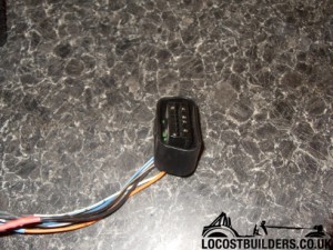
The pin’s are numbered as below.
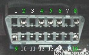
Not all pins are used. you have power and earth as well as can bus ect.
Injectors
1
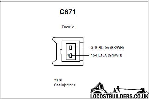
2
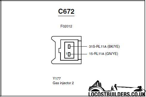
3
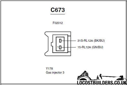
4
Cam sensor.
Fuel pressure sensor on the end of the fuel rail.
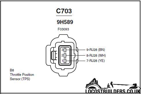
Throttle position sensor.
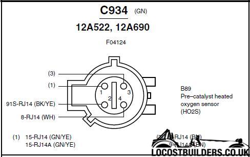
Pre cat O2 sensor.
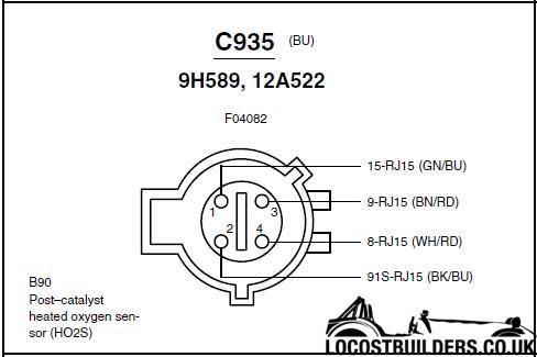
Post cat O2 sensor.
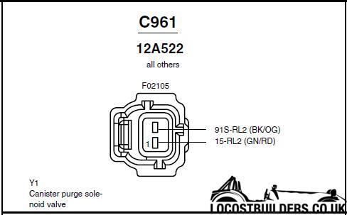
Purge valve.
Idle control valve.
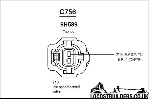
Fuel pump control module.
Knock sensor.

Inlet manifold runner control module.
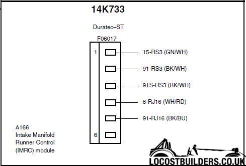
Mass air flow meter.
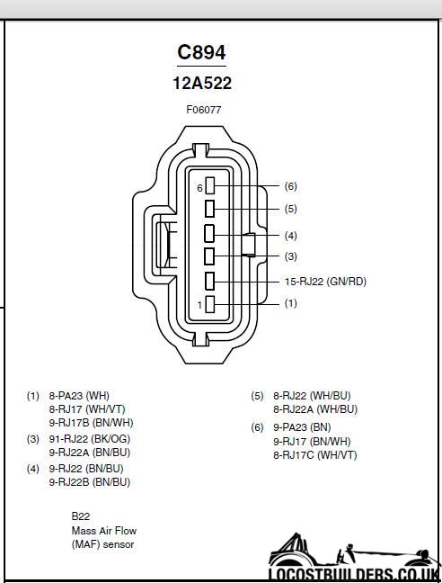
Hope this helps any one wanting to run an St170 without spending shed loads. Its no harder than making a loom for a MS ecu just more of it. There is
no mapping and the ecu can be had for a few quid. They are called an St170 as they are meant to be 170 ps at the fly'. NOT all are but by no
means are they all dogs. The key to keeping them on song is to make sure all sensors and actuators are tickerty boo.
[Edited on 13/4/14 by big_wasa]
|
|
|
|
|
ceebmoj
|
| posted on 13/4/14 at 07:23 PM |

|
|
Thank you for the information great post
|
|
|
coozer
|
| posted on 13/4/14 at 07:29 PM |

|
|
Great post.
Just to add the pats receiver can also be found on any X type Jaguar.
1972 V8 Jago
1980 Z750
|
|
|
big_wasa
|
| posted on 13/4/14 at 07:35 PM |

|
|
More plugs for you to eliminate.
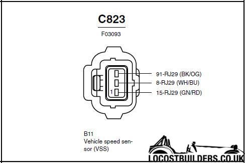
Speed sensor found in the gear box.
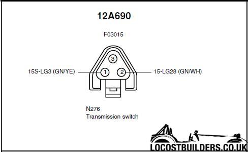
Reverse switch found in the gearbox.
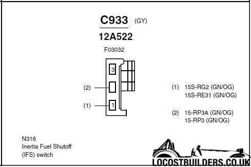
Inertia switch found in the fuel pump feed.
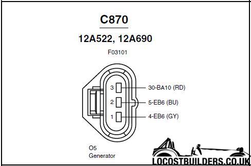
Alternator.
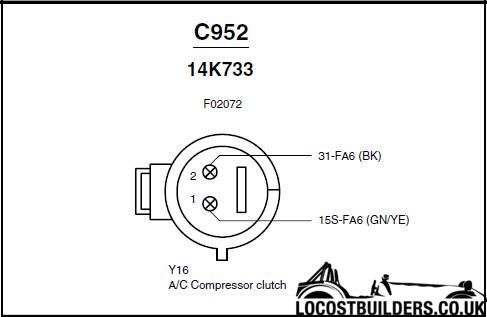
Ac clutch (ecu controlled )
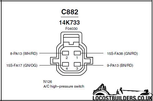
Ac high pressure switch.
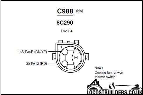
You will se an ecu pin for the high speed fan. This is for the Ac. The coolant fan is done the old school way on the St170 with a switch in the rad.
This is the same M22x1.5 as the the polo rad so the switch is a direct transplant and will work at the designed temp.
I will add more as I remember and as I go but I wont have time to do a "wiring diagram" I've tried and it just looks like
spaghetti.
cheers
|
|
|
big_wasa
|
| posted on 13/4/14 at 07:37 PM |

|
|
quote:
Originally posted by coozer
Great post.
Just to add the pats receiver can also be found on any X type Jaguar.
That's because it uses the ford platform, S type is different.
|
|
|
coozer
|
| posted on 13/4/14 at 08:37 PM |

|
|
quote:
Originally posted by big_wasa
quote:
Originally posted by coozer
Great post.
Just to add the pats receiver can also be found on any X type Jaguar.
That's because it uses the ford platform, S type is different.
Its because the Mondeo and X type use the same steering column (as well as most other parts) and Ford passed it onto the Focus at the same time.
Funny thing is the column went on the mondeo until 2007 when Ford moved onto the new platform, that killed the X type off BUT the factory I worked in
still make the column now for the DB9...
1972 V8 Jago
1980 Z750
|
|
|
garybee
|
 posted on 14/4/14 at 11:58 AM posted on 14/4/14 at 11:58 AM |

|
|
That is absolutely fantastic, must have been quite a job.
One quick question (and sorry if I've missed it and the answer's there), what is the orientation of the pictures? Are they looking
towards the loom from the component or towards the component from the loom?
Many thanks
Gaz
|
|
|
big_wasa
|
| posted on 17/4/14 at 05:35 PM |

|
|
looking at the pins I think but the plugs do have numbers next to the pins.
|
|
|
garybee
|
| posted on 17/4/14 at 07:08 PM |

|
|
It'll be easy enough to work out with the loom in your hand anyway, as the wire colours are there.
|
|
|
Your-nme
|
| posted on 23/4/15 at 06:45 PM |

|
|
Hi Big_wasa,
I saw in another Post that you where wondering if somebody was trying to get an st170 running with the original ecu. My answer is Yes. But i'm
strugling a bit. The Pats is working, got no spark and fuel pump shuts of after 3 sec but looks like this is not due to the pressure sensor.
Any suggestions?
Thanks,
DJ
|
|
|
big_wasa
|
| posted on 23/4/15 at 07:06 PM |

|
|
Hi, nice to see some one having ago.
So you have the pats led connected ? You turn the ignition on and the light stops flashing and goes solid on for a short time ? The pump then runs for
a few seconds ? When you crank the engine what does the light do ?
It won't fire the coil if there is no crank or cam signal.
Connect an obd2 device and view the live data. Is the ecu seeing the engine turn over ?
|
|
|
Your-nme
|
| posted on 23/4/15 at 07:21 PM |

|
|
So you have the pats led connected ? Yes
You turn the ignition on and the light stops flashing and goes solid on for a short time ? Yes
The pump then runs for a few seconds ? Yes
When you crank the engine what does the light do ? The led turns of and stays off
Have the odb2 connected. Can see the live data as temp and throttle position. But when i crank the engine is see no changes on the screen.
|
|
|
big_wasa
|
| posted on 23/4/15 at 07:25 PM |

|
|
It should read an rpm so my guess is the ecu is not seeing the crank or cam sensor. Check the wiring and polarity. With no signal it won't fire
the coil and it will cut the fuel pump.
|
|
|
big_wasa
|
| posted on 23/4/15 at 07:33 PM |

|
|
Is there any posability the engine had an automatic gearbox ? I've never seen an automatic St but I don't pretend to know everything. What
flywheel do you have ? Is there any chance the cps housing has been swaped for one from an auto ?
|
|
|
Your-nme
|
| posted on 23/4/15 at 07:59 PM |

|
|
Cam sensor is connected correct.
I kept the original wiring of the st170.
It was a manual gearbox. I used the flywheel that was on the previous engine. Cvh 1,6 with a t9 gearbox.
The sensor that is pointed to the flywheel. Can this be the problem? Because the original flywheel of the st170 has a pattern for the sensor. The cvh
doesn't have it.
A few wires that i could not find a logic point to connect to:
27 start inhibit relay
17 high speed fan
69 engine cooling fan
91 common brown
But don't think they influance the working of the engine. I think

[Edited on 23/4/15 by Your-nme]
|
|
|
big_wasa
|
| posted on 23/4/15 at 08:24 PM |

|
|
Yes that's your problem. The only cvh flywheel that will work is the very late 90 spec efi engines like the rs turbo and xr3i. Get your self a
1.8 zetec flywheel.
Re the wiring. Starter inhibit relay. The ecu stops the engine being cranked over while being immobilised. You can live with out that when it's
wired properly. You can leave the fan wires most are for the ac. You must switch the fan on in another way ie switch in the rad.
The sensor common is VERY important. This is the common earth to most sensors. NOT A CHASSIS EARTH.
|
|
|
Your-nme
|
| posted on 23/4/15 at 08:40 PM |

|
|
Okay,
So the zetec 1.8 flywheel also has the pattern as the st170?
Just to confirm because I'm a hobby electrician. The common sensor wire. I have to connect it to the negative of the battery.
So will try to get an flywheel of a zetec 1.8.
|
|
|
big_wasa
|
| posted on 23/4/15 at 08:54 PM |

|
|
So the zetec 1.8 flywheel also has the pattern as the st170?
YES 36-1 you could also use a trigger wheel on the front crank pulley. It's not a bolt on item.
Just to confirm because I'm a hobby electrician. The common sensor wire. I have to connect it to the negative of the battery.
NO NO NO NO YOU WILL POP THE ECU. Ecu to the sensors that need it ONLY ! Black and yellow trace, Black and red trace are chassis earth.
|
|
|
Your-nme
|
| posted on 24/4/15 at 12:39 PM |

|
|
Maybe a stupid question.
I have found a 1.6 / 2.0 zetec flywheel with all parts. Assuming this will do the trick.
Or is there a big difference between zetec 1.8 and the mentioned one.
Can't see any big difference on the pictures.
|
|
|
big_wasa
|
| posted on 24/4/15 at 03:56 PM |

|
|
There are two types of zetec. The zetec E and the zetec SE.
You can indeed get a 1.6 zetec E which is a silver top engine. It's the same flywheel as the 1.8 silver top or black top.
But when the engines went from silver top to black top ford dropped the 1.6 zetec E and replaced it with the all alloy zetec SE also known as the
sigma.
The 2.0 clutch is 240mm and the 1.8 / 1.6 is 220mm.
So yes an early 1.6 fly will fit but a later 1.6 fly will not.
Keep us posted and I'd didn't start if there was no video 
|
|
|
Your-nme
|
| posted on 24/4/15 at 04:58 PM |

|
|
This is the parts I am trying to purchase.
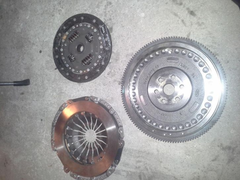 
flywheel
Have requested the diameter of the frictionplate.
my project
 
Description1
 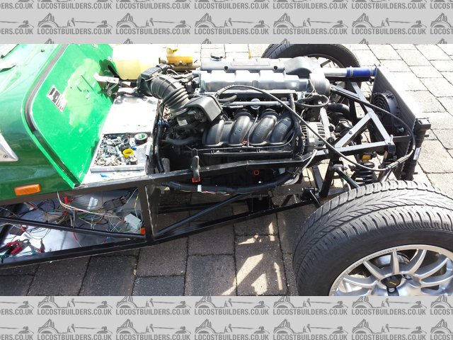
2
Description
|
|
|
big_wasa
|
| posted on 24/4/15 at 08:02 PM |

|
|
Shame you're not local. I have a flywheel that should work that I keep tripping over. Its a very rare sierra cfi. Its already rwd to t9 so no
need for the thicker thrust bearing.
|
|
|
Your-nme
|
| posted on 24/4/15 at 08:13 PM |

|
|
I will be in the uk on the 15 of may. But that will be near birmingham. Have purchased a new body for my westfield.
Am driving via the eurotunnel so spalding is a bit in the wrong direction.
|
|
|
Your-nme
|
| posted on 17/5/15 at 07:28 PM |

|
|
I installed a new 2.0 zetec flywheel. Finally its running.
Only for a few seconds but that is because I still have IMRC not working (That is what I think). Only have connected the wires as you mention. But
struggling with the ground and switched ground leads.
First will make the exhaust with both sensors. i hope it will work when I will put these behind each other.
|
|
|
big_wasa
|
| posted on 17/5/15 at 07:44 PM |

|
|
It will run with out the irmc but not at its potential, it will also give a fault code.
But if it fires you are getting there.
If a sensor has a brown wire it goes back to the ecu. Its a sensor ground It's not a chassis ground.
|
|
|


