PAUL FISHER
|
| posted on 30/12/07 at 05:14 PM |

|
|
quote:
Originally posted by procomp
Hi yep the top joint on the new mk has the exact same problem as the old one in that the angle of the joint dose not allow full articulation IE the
joint runs out of travel before the damper dose. Quite amazing they havent corrected that problem considring how bad a flaw it is.
Cheers matt
How you can possibly make a statement like that from looking at a picture of an upright from that angle,not even knowing from the picture if the other
end of it was even connected to the car,or if the suspension has even been adjusted or tightend,is beyond me,and from someone with your experience.But
all is explained when reading through your past posts,that you have major issues with MK,and in my opinion for a manufacturer who users this forum to
carry out some personal vendetter against another manufacturer,and in the case of MK,a manufacturer who does not post on this forum and are unable to
defend themselves,is very underhand,and that's putting it politely.
I know the designer of the chassis personally,and in my opinion and many other professionals in the industry he has done a fantastic job,and all this
within the constraints of the car keeping its original silhouette,also a professional racing driver has driven the car on track and his feed back has
been excellent,I feel MK and their designer should be applauded for providing their customers with yet another great value for money bit of kit,and I
and an average of 5 new customers a week are very happy with our cars.
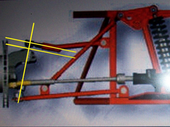
Below is a picture from the correct angle,to enable a fair judgement to be made on whether the ball joint will run out of acticulation,before maximum
suspension travel is reached,as you can see the ball joint is at around 90 degrees to the upright at rest,so in a central position to allow full
acticulation of the joint in both directions,this acticulation goes well beyond the maximum travel of the shock absorbers in both
directions.FACT
 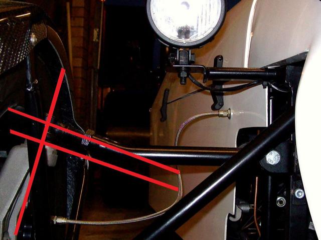
Rescued attachment the 90.jpg
|
|
|
|
|
PAUL FISHER
|
| posted on 30/12/07 at 05:17 PM |
|
|
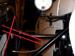
Also just to add pictures of the original design of the suspension travel,at rest,and at maximum travel
 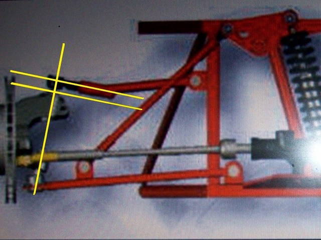
Rescued attachment THE 3.jpg
|
|
|
PAUL FISHER
|
| posted on 30/12/07 at 05:18 PM |
|
|
This shows the suspension at a position at maximum travel and clearly showing the ball joint angle no where near its maximum acticulation
[Edited on 19/05/04 by PAUL FISHER]
 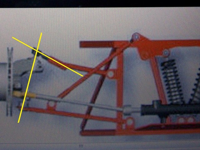
Rescued attachment the 78.jpg
|
|
|
t.j.
|
| posted on 30/12/07 at 05:37 PM |
|
|
It is right that the upper balljoint must NEVER reach the end.
The shock-absorber should be stopping the movement or something other than the ball-joint.
I presume MK did the angle to prevent this.
[Edited on 30/12/07 by t.j.]
Please feel free to correct my bad English, i'm still learning. Your Dutch is awfull! :-)
|
|
|
procomp
|
| posted on 30/12/07 at 06:31 PM |
|
|
Hi there are no personal vendettas with any one on here. I am simply voicing an opinion based on fact having worked on one of the cars. And having had
discussions with other owners who have also expressed concerns.
I will send you a u2u to continue discussion if you wish.
Cheers Matt
|
|
|
Uphill Racer
|
| posted on 30/12/07 at 09:34 PM |
|
|
quote:
Originally posted by JoelP
anyway i thought uphill racer was refering to the bend in the back leg!
Yes, that was my point.
Paul look at the pics where the yellow line dissapears under the top wishbone. Now visualise what is happening there under braking and cornering
loads.
[Edited on 30/12/07 by Uphill Racer]
|
|
|
PAUL FISHER
|
| posted on 30/12/07 at 11:04 PM |
|
|
quote:
Originally posted by Uphill Racer
quote:
Originally posted by JoelP
anyway i thought uphill racer was refering to the bend in the back leg!
Yes, that was my point.
Paul look at the pics where the yellow line dissapears under the top wishbone. Now visualise what is happening there under braking and cornering
loads.
[Edited on 30/12/07 by Uphill Racer]
I understand your concerns Uphill Racer,but this chassis has not been drawn up with a piece of paper and a pencil,the latest computer aided design has
gone into its innovative design,simulations on stress points and material used have been made,also extensive track testing over the last 18months,with
various cars including a supercharged gsxr 1000 on up to 220mm wide slicks has highlighted no problems,regards Paul
|
|
|
PAUL FISHER
|
| posted on 30/12/07 at 11:21 PM |
|
|
quote:
Originally posted by procomp
Hi there are no personal vendettas with any one on here. I am simply voicing an opinion based on fact having worked on one of the cars. And having had
discussions with other owners who have also expressed concerns.
I will send you a u2u to continue discussion if you wish.
Cheers Matt
I feel what needs to be discussed can be done so openly on this forum ,I have clearly shown my evidence that there is no fault with the design of the
top front wishbone or ball joint articulation angle.regards Paul
|
|
|
oadamo
|
| posted on 30/12/07 at 11:37 PM |
|
|
ill prob get slated. but to me the uprights are not made to be used for this car thats why they have bent the top arm to suit. its just bad
engineering.
adam
|
|
|
Uphill Racer
|
| posted on 31/12/07 at 12:28 AM |
|
|
quote:
Originally posted by PAUL FISHER
quote:
Originally posted by Uphill Racer
quote:
Originally posted by JoelP
anyway i thought uphill racer was refering to the bend in the back leg!
Yes, that was my point.
Paul look at the pics where the yellow line dissapears under the top wishbone. Now visualise what is happening there under braking and cornering
loads.
[Edited on 30/12/07 by Uphill Racer]
I understand your concerns Uphill Racer,but this chassis has not been drawn up with a piece of paper and a pencil,the latest computer aided design has
gone into its innovative design,simulations on stress points and material used have been made,also extensive track testing over the last 18months,with
various cars including a supercharged gsxr 1000 on up to 220mm wide slicks has highlighted no problems,regards Paul
Paper and pencil, how derogetory. Computer programs allow engineers to proove basic problems, it needs them to understand the problem from 1st
principals. Your top upright when it fails on a car and sooner or latter 1 will because of the constant unsuported loading outboard and in a
different plane than the wishbone I hope they have insurance that covers them for incompetence
[Edited on 31/12/07 by Uphill Racer]
|
|
|
PAUL FISHER
|
| posted on 31/12/07 at 03:42 AM |
|
|
quote:
Originally posted by Uphill Racer
quote:
Originally posted by PAUL FISHER
quote:
Originally posted by Uphill Racer
quote:
Originally posted by JoelP
anyway i thought uphill racer was refering to the bend in the back leg!
Yes, that was my point.
Paul look at the pics where the yellow line dissapears under the top wishbone. Now visualise what is happening there under braking and cornering
loads.
[Edited on 30/12/07 by Uphill Racer]
I understand your concerns Uphill Racer,but this chassis has not been drawn up with a piece of paper and a pencil,the latest computer aided design has
gone into its innovative design,simulations on stress points and material used have been made,also extensive track testing over the last 18months,with
various cars including a supercharged gsxr 1000 on up to 220mm wide slicks has highlighted no problems,regards Paul
Paper and pencil, how derogetory. Computer programs allow engineers to proove basic problems, it needs them to understand the problem from 1st
principals. Your top upright when it fails on a car and sooner or latter 1 will because of the constant unsuported loading outboard and in a
different plane than the wishbone I hope they have insurance that covers them for incompetence
[Edited on 31/12/07 by Uphill Racer]
Ask a derogatory question,you get a derogatory answer
[Edited on 19/05/04 by PAUL FISHER]
|
|
|
PAUL FISHER
|
| posted on 31/12/07 at 04:05 AM |
|
|
quote:
Originally posted by oadamo
ill prob get slated. but to me the uprights are not made to be used for this car thats why they have bent the top arm to suit. its just bad
engineering.
adam
Now thats just derogatory
|
|
|
procomp
|
| posted on 31/12/07 at 12:34 PM |
|
|
Hi well here are my finding after some discussion with the owner of the car that i had been working on.
In order to gain at least some sort of control of the camber and to induce more mechanical grip from the tyre footprint we had decided to run the car
at the lower end of the ride height that was available. This was working quite nicely except for the fact that when the car was in corners such as the
old hairpin at donnington where the car would be in a bump and roll situation IE not just a bump situation that is where it was found that the top
joint ran out of travel.
Also if i can draw your attention to the above pictures. How come in the one the damper and spring on the drivers side that we are looking at are the
same as the other side on the lower picture. And then on the lower picture where both dampers are in view you can quite clearly see that the spring on
the drivers side that we are looking at are not the same as the spring on the other side. It is quite clearly of different wire gauge. Which to me
indicates that you have done some swapping of dampers to achieve a lesser movement of the setup. And can also be seen by the fact that the damper is
shown in full droop and then in full compression. However the spring dose not seem to have compressed by the same amount that the damper appears to
have. Although the lower spring platform seems to be in a very similar position.
I think that this will end in nothing but an ongoing discussion with no point to it at the end. Other than a difference of opinion. I have said my
piece and will leave it at that. But as has been pointed out by Uphill Racer there is some bad engineering there and for no reason what so ever as it
did not need to be off that design to achieve the same result but in a manner that would have been far better engineered and not off caused there to
be a potential problem with that top joint.
Cheers Matt
|
|
|
t.j.
|
| posted on 31/12/07 at 06:16 PM |
|
|
I've seen today a wishbone from a MK with angled top balljoint.
IMO it will not a bigger problem than not angled.
I would say if there is enough "meat" which can be welded to the threaded part. So the old style wishbone in a V is IMO better than those
nicely bent wishbone which have only about 3,14x25 mm is welded.
I would like to know now if the ball-joint reaches his end or not.
If not this discussion should be closed.
I had the same problems using the transit M20x1,5 ball-joint at full-drop. It happened when the inner brackets of the upper-wishbone where not placed
at the exact place.
Maybe MK limited the travel tru the bump-stop? So before we make conclusions first let someone have a look if the travel is limited by the ball-joint.
If not this is IMO a non-issue
Please feel free to correct my bad English, i'm still learning. Your Dutch is awfull! :-)
|
|
|
Peteff
|
| posted on 31/12/07 at 06:32 PM |
|
|
Well
It makes sense to me now that I can see the top ball pin is 90° to the insert in the upright on the MK wishbone. I've helped on Indy and MAC#1
and never took notice of it before to tell the truth.
yours, Pete
I went into the RSPCA office the other day. It was so small you could hardly swing a cat in there.
|
|
|
Rob Lane
|
| posted on 1/1/08 at 11:56 AM |
|
|
Balljoints differ from manufacturer to manufacturer.
I've personally bought at least 10 different sets and found articulation in the same joint to vary quite considerably.
Some to the extent that a fully articulated joint in one setup became 'bound' when joint replaced by another.
However, that said, the pics look OK and shouldn't be used as reference. Only in the 'flesh' so to speak can you really make
comment. Until then accept the word of the poster.
|
|
|