minto4
|
 posted on 12/8/06 at 11:02 AM posted on 12/8/06 at 11:02 AM |

|
|
Megajolt Communications Problems
Hi all Decided to build a megajolt unit for the tiger to do away with the worn distributer systen.
Last night i had all the parts to build the board, so i did.
All going well till trying to connect it to the laptop. It just wont communicate. I have also tried my PC this morning to no avail.
Looking at the Megajolt web site it appears this is a very common problem but not being very helpfull in sorting it.
Wondering if their is anybody round the preston area who has the Megajolt working and communicating that might be able to help.
Thanks for looking, Ben
|
|
|
|
|
rayward
|
| posted on 12/8/06 at 11:15 AM |
|
|
did you have 12v to the unit??.
which version of the software are you using?, java or non java??.
Ray
|
|
|
minto4
|
| posted on 12/8/06 at 12:27 PM |
|
|
Yes i've got the unit powered up, and i have tried to use both programms from the megajolt site and also hyper terminal to communicate with
it.
do you know for sure which terminals need to be connected in the serial lead, is it just 2+3?????
Gonna do my nut in soon.
|
|
|
rayward
|
| posted on 12/8/06 at 12:44 PM |
|
|
you need pins 1,2,3,5 and 9 connected straight through i.e 1 - 1, 2-2 etc.
Ray
|
|
|
minto4
|
| posted on 12/8/06 at 12:48 PM |
|
|
Are those pins deffo right as their are so many defferent posts on the site and nothing for sure.
I appreciate your help very much.
|
|
|
the_fbi
|
| posted on 12/8/06 at 12:53 PM |
|
|
No idea about MS, but at the very least you'll need 2,3,5 for RS232c (TX,RX,Sig Gnd)
|
|
|
the_fbi
|
| posted on 12/8/06 at 12:54 PM |
|
|
quote:
Originally posted by minto4
Are those pins deffo right as their are so many defferent posts on the site and nothing for sure.
I appreciate your help very much.
Given what he is "Building" its probably right 
|
|
|
minto4
|
| posted on 12/8/06 at 12:58 PM |
|
|
My bad sorry.
|
|
|
minto4
|
| posted on 12/8/06 at 01:32 PM |
|
|
This is the board i built could you check to see if it all looks good and i have the right parts for the communication.
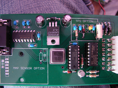 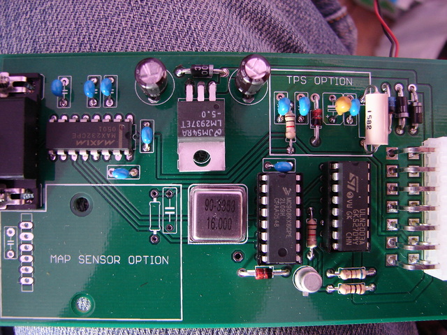
Rescued attachment DSC01996.JPG
|
|
|
the_fbi
|
| posted on 12/8/06 at 01:44 PM |
|
|
I may be missing something, but it doesn't appear that you've soldered a load of the connections.
Top left cap.
Cap under the max232.
Few max232 pins.
TPS caps.
Top right diode.
I've never seen an MS board in the flesh, perhaps they can be soldered on the reverse?
If you've made the serial cable up as rayward said and still not getting anywhere, double check all component positionings and see if
you've got any dry joints.
Failing that get yourself http://www.sysinternals.com/utilities/portmon.html and log your com1 (or whatever your connecting it to). Turn on the hex
log too, it'll show you exactly what is going on and where in the process its stopping and also give some details of how its trying to
"talk", handshake etc.
|
|
|
minto4
|
| posted on 12/8/06 at 02:00 PM |
|
|
just tried the port monitor and this is what i got, just to add its the same when i unplug the jegajolt.
also checked all the joints twice and all good as far as i can see, the components are soldered from the other side what you can see are ones that
have not flowed all the way through but do have a good connection
|
|
|
the_fbi
|
| posted on 12/8/06 at 02:04 PM |
|
|
Well its getting nothing back from the MS.
I was suprised when rayward said 2-2 and 3-3, I'd expect 2-3 and 3-2.
Have you got all the connections he said currently wired up?
If so, try putting 2 to 3 and 3 to 2.
Your PSU is definately working OK?
|
|
|
minto4
|
| posted on 12/8/06 at 02:08 PM |
|
|
I have a regulated 12v psu running the unit while testing, checked all the voltages while building all good 5v + 12v
|
|
|
the_fbi
|
| posted on 12/8/06 at 02:11 PM |
|
|
Just noticed its a 9way not a 25way so 2-2 and 3-3 is plausable. Although depends how its designed.
I don't suppose you feel like tracing back pins 2 and 3 to the max232 and seeing which pin they go to?
I think we'll have to presume ray was right.
Your serial port testable on anything else to prove its OK?
|
|
|
the_fbi
|
| posted on 12/8/06 at 02:17 PM |
|
|
Reading the MJ forums.... Can you do this test?
The problem was a faulty oscillator (QG1)- the diagnosis is that pin 10 of U1 (the main processor) should have a 16Mhz square wave on it.
If you don't have an oscilloscope to hand to check, you can measure the voltage with a multimeter - should be 2.4 volts or so.
My faulty one had no square wave and 0 volts when measured at pin 10 of U1.
Replaced the oscillator (it was brand new anyway) with another and instant success.
[Edited on 12/8/06 by the_fbi]
|
|
|
viatron
|
| posted on 12/8/06 at 03:06 PM |
|
|
Just finished using my laptop with cable on the Avon at a rolling road session at Bogg Bros, could check when i get home excatly what the pinouts for
the cable should be if it would help? Also are you using a normal comm port or a usb adapter? i am using a USB adapter and have no problems but some
people seem to have issues with them, i think its down to there being a couple of types, mine is based on the prolific chipset and works fine.
Mac
|
|
|
viatron
|
| posted on 12/8/06 at 03:08 PM |
|
|
also just rechecked the photo you posted and at least one of the dry joints appears to be on a track on the surface of the board not underneath, maybe
im being anal but i would want to see solder both sides on every joint.
JMO!!
Mac
|
|
|
rayward
|
| posted on 12/8/06 at 03:46 PM |
|
|
first thing to do is check the port and cable are working, the pins 1,2,3,5 and 9 are definately correct so....
at the MJ end of your cable link pins 2 and 3.
run hyperterminal on your pc, set the com port settings to the port your using(com1 i guess??).
with local echo turned of, if the cable and port is working, you should get every character you type bounced down the cable, across the pin2-3 link
and black to your screen,(with local echo turned on you should get everything twice).
this will confirm the cable and port are fine.
Ray
|
|
|
minto4
|
| posted on 12/8/06 at 04:30 PM |
|
|
quote:
Originally posted by the_fbi
Reading the MJ forums.... Can you do this test?
The problem was a faulty oscillator (QG1)- the diagnosis is that pin 10 of U1 (the main processor) should have a 16Mhz square wave on it.
If you don't have an oscilloscope to hand to check, you can measure the voltage with a multimeter - should be 2.4 volts or so.
My faulty one had no square wave and 0 volts when measured at pin 10 of U1.
Replaced the oscillator (it was brand new anyway) with another and instant success.
[Edited on 12/8/06 by the_fbi]
I do happen to have an oscilloscope as it happens, it is a rellic but it does the job. I checked pin 10 and it is showing 2.5 v as stated.
i also checked all the pins with my fluke and it shows continuity between all the pins top and bottom of the board and to where the go.
I have also already checked the port linking 2-3 and it shows an echo.
i am trying to connect with my PC which has a physical com port on the back so it shouldnt be a problem.
Who said modern technology was a good thing!!!!1
|
|
|
rayward
|
| posted on 12/8/06 at 06:21 PM |
|
|
if you've got 5v on the correct pins on the max232, and still not working, i would replace the max232, failing that, possibly a faulty
processor.
whereabouts are you?, if your anywhere near, you welcome to plug your MJ into my laptop just to check, or failing that you could post it to me.
Ray
[Edited on 12/8/06 by rayward]
|
|
|
minto4
|
| posted on 12/8/06 at 06:59 PM |
|
|
if i posted it to you could you give it a checking over and se whats what. i take it you would have the parts to sort any possible problems???
your not going to the kit car show tomorrow in harrogate are you???????
|
|
|
minto4
|
| posted on 12/8/06 at 07:01 PM |
|
|
on that note i dont suppose anyone who hase a working laptop and megajolt is attending the car show tomorrow are they?????
|
|
|
rayward
|
| posted on 12/8/06 at 09:00 PM |
|
|
i can check it out/repair it for you if you want no probs.
i might be going tomorrow, if you let me have your mobile number, i'll give you a ring if i;m there.
Ray
|
|
|
MikeRJ
|
| posted on 12/8/06 at 09:52 PM |
|
|
Just to check, you do definately have a programmed micro don't you?
|
|
|
MikeRJ
|
| posted on 12/8/06 at 09:59 PM |
|
|
quote:
Originally posted by viatron
also just rechecked the photo you posted and at least one of the dry joints appears to be on a track on the surface of the board not underneath, maybe
im being anal but i would want to see solder both sides on every joint.
JMO!!
Mac
They are not dry joints, the solder has simply not wicked through the joint. This shouldn't be a problem as the board has plated through holes,
though it's not ideal from a mechanical point of view.
I've built a few Megajolts and suffered from the same problem, which is down to poor board design. Solder pads on ground/power planes should be
connected by four small tracks radialy from the pad (known as a 'thermal pad' to prevent the power plane sinking all the heat away from
the board. to prevent the power plane sinking all the heat away from
the board.
You can top solder the joints, but this can cause more problems than it's worth as it's very easy to overheat the component with the
soldering iron that close to it.
|
|
|


