TangoMan
|
| posted on 27/2/07 at 11:23 PM |

|
|
Zetec Sender Units
I am now at the point of wiring in my MS as the engine swap is nearly finished.
I am unsure about the temp sensors though as
1) there are two of them on the thermostat housing.
2) they both have two wires.
Am I right in thinking that the top one is for temp sensing to feed the ECU (MS) with the second wire going to earth.
If so, then I guess the other (bottom exhaust side) is to feed the gauge, with the second wire again as an earth.
I don't know why they didn't stick with using the body of the sender as an earth!!
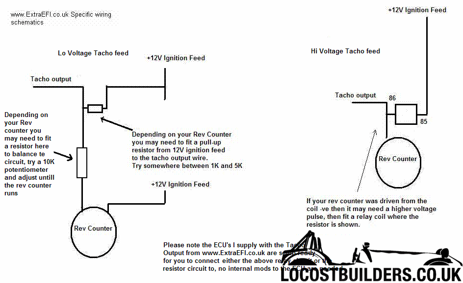
The only other bit I am unsure of is the rev counter wiring. When the manual says to use a relay coil, is this simply wiring through a standard relay
without connecting to the switched connections?
I am hoping to be up and running again soon as the sun is starting to shine so any advice would be appreciated.
Thanks,
Steve
Summer's here!!!!
|
|
|
|
|
stevebubs
|
| posted on 27/2/07 at 11:29 PM |

|
|
quote:
Originally posted by TangoMan
I am now at the point of wiring in my MS as the engine swap is nearly finished.
I am unsure about the temp sensors though as
1) there are two of them on the thermostat housing.
2) they both have two wires.
Am I right in thinking that the top one is for temp sensing to feed the ECU (MS) with the second wire going to earth.
If so, then I guess the other (bottom exhaust side) is to feed the gauge, with the second wire again as an earth.
I don't know why they didn't stick with using the body of the sender as an earth!!
Yes - one side to common earth, other to signal on the gauge / ECU ; because
a) the plastic housing doesn't
conduct?
b) if you run the earth back to the same point, any noise introduced on the signal line should also be introduced on the earth which should lead to a
"cleaner" signal.
|
|
|
TangoMan
|
| posted on 28/2/07 at 12:16 AM |

|
|
quote:
Originally posted by stevebubs
the plastic housing doesn't
conduct?
Pretty obvious really, I'm kind of embarrased that I asked now. Now where did I leave that dunce's hat. 
Thanks for the confirmation though.
Steve
Summer's here!!!!
|
|
|
TangoMan
|
| posted on 28/2/07 at 08:50 AM |

|
|
OK so having slept on it, I am now OK with the wires but am I correct on the top sender being for ECU and the lower one for the gauge.
Also, when the tacho wiring states to use a relay coil, is this simply wiring it through a relay without any connections to the switched side or is a
relay coil something else.
So many questions  
Summer's here!!!!
|
|
|
stevebubs
|
| posted on 28/2/07 at 07:50 PM |

|
|
Not sure on the sender bit. Certainly how mine are wired up but I've changed both mine from standard.
can you point me to where in the docs the relay is mentioned?
|
|
|
paulf
|
| posted on 28/2/07 at 09:01 PM |

|
|
Ive seen it mentioned that it is possible to use a relay coil to give a higher voltage kick for the type of tacho that relys on back EMF to operate.
Most newer ones will work off a 12 volt impulse signal.
I assume it would be conected across the 12volt tacho as if it was an ignition coil primary , however i would be a bit concerned about damaging the
ecu by back emf spikes.
Paul.
quote:
Originally posted by stevebubs
Not sure on the sender bit. Certainly how mine are wired up but I've changed both mine from standard.
can you point me to where in the docs the relay is mentioned?
|
|
|
TangoMan
|
| posted on 28/2/07 at 11:05 PM |

|
|
I can't remember where I have seen it now. I have a paper copy but cannot see the electronic version I should have saved on my PC.
I was a bit concerned that 12v might blow the tacho but hand't thought about any damage to the MS. Perhaps I will try without the additional
feed and see if I get a reading on the gauge.
Summer's here!!!!
|
|
|
TangoMan
|
| posted on 28/2/07 at 11:23 PM |

|
|
Found it!!!


Summer's here!!!!
|
|
|
paulf
|
| posted on 1/3/07 at 12:04 PM |

|
|
The additional feed will be ok to use, try connecting it with a 5k resistor first, it is used to give a proper 12v on off signal to the tacho as many
require a 12v swing on the signal to operate.
Paul.
|
|
|


