DaveFJ
|
| posted on 24/8/07 at 08:23 AM |

|
|
Some more numpty EFI questions!
OK.. prepare for some numpty questions!
I am currently trying to sort out the wiring under the bonnet. I have a MSnS extra which I bought built and came complete with wired 37pin plug. (No
EDIS etc just straight drive to Mondeo coil pack).
I am fitting a set of GSXR750/1000 K2 throttle bodies to a Pinto.
I also have an LC1 wideband O2 sensor to plumb in.
I have a few questions and although i spent yesterday evening searching this site - and others - I am still none the wiser...
My questions are:
1. My wiring from the ecu has 1 wire for FI valve and 4 wires for IAC stepper. What do I need to connect to what? do I need to obtain one of these, or
both? If so how do they fit?
2. My TBs have a 4 branch vacuum tube joined each body, what does this join to? from what I have read I thought this was for connecting to MAP sensor
but I have (I believe) a TPS on the end of the main butterly spindle?
3. I understand that the secondary butterfly's should be removed complete with the actuator on the end and what would appear to be another TPS
for the secondary spindle - is this correct?
4. Where do I get the signal for my Tacho? there is no wire from the ecu for this....
5. I have another question about the Tiger loom but will post that on the Tiger Avon section.....
Having enormous fun at the moment sorrounded by piles of spaghetti !

To be fair - I knew this was never going to be the 'easy bit'....
[Edited on 24/8/07 by DaveFJ]
Dave
"In Support of Help the Heroes" - Always
|
|
|
|
|
paulf
|
| posted on 24/8/07 at 10:03 AM |
|
|
1. Dont bother with a fast idle valve, leave the wires disconected, most people find that the engine runs fine after just a short warm up time and it
is easy to just blip the throttle when cold.
2.The ECU needs a vacuum and TPS signal so there should be a connection to it for the vacuum.
3.Correct just remove it all and plug the holes in the throttle bodys , I made some alloy plugs but most people just use plastic metal or similair.
4. The tacho signal can be taken from the ECU but it may need an internal Mod to connect it to the 37 pin plug, an alternative is to take a signal
from the coil connections via a couple of diodes.
Paul.
|
|
|
DaveFJ
|
| posted on 24/8/07 at 10:26 AM |
|
|
now you have me worried on question 2
The ecu has no connection for a Vacuum signal? and looking through the various connection diagrams I can see no mention of it? I guess I am being
thick again?
connections I have are:
6 spark B
20 Air temp
21 H2O temp
22 TPS sig
23 O2 sensor
24 VR sensor +
25 IAC Stepper
26 TPS V ref
27 IAC Stepper
28 +12V in
29 IAC Stepper
30 FI Valve
31 IAC Stepper
32 Bank 1 inj's
33 Bank 1 inj's
34 Bank 2 inj's
35 Bank 2 inj's
36 Spark output A
37 Fuel Pump relay
Not quite sure what to do with air temp sensor is either!
Dave
"In Support of Help the Heroes" - Always
|
|
|
piddy
|
| posted on 24/8/07 at 11:08 AM |
|
|
Hi.
My Mega squirt has a plastic tube in the end that you attach the vacuum tube to and then this tube connects into the inlet manifold or carbs ect.
[Edited on 24/8/07 by piddy]
|
|
|
paulf
|
| posted on 24/8/07 at 01:54 PM |
|
|
Did you but it new? where from?
There will almost certainly be a map sensor in it although if not new someone may have been configered it to run on TPS signal only in Alpha N mode
.
Undo the case and there should be a round black sensor about 20mm dia soldered to the board with a barbed pipe fitting on it.
Paul.
quote:
Originally posted by DaveFJ
now you have me worried on question 2
The ecu has no connection for a Vacuum signal? and looking through the various connection diagrams I can see no mention of it? I guess I am being
thick again?
connections I have are:
6 spark B
20 Air temp
21 H2O temp
22 TPS sig
23 O2 sensor
24 VR sensor +
25 IAC Stepper
26 TPS V ref
27 IAC Stepper
28 +12V in
29 IAC Stepper
30 FI Valve
31 IAC Stepper
32 Bank 1 inj's
33 Bank 1 inj's
34 Bank 2 inj's
35 Bank 2 inj's
36 Spark output A
37 Fuel Pump relay
Not quite sure what to do with air temp sensor is either!
|
|
|
DaveFJ
|
| posted on 24/8/07 at 02:02 PM |
|
|
Pretty sure there isn't - and having looked through the Megasquirt stuff I still can't find any piccy's that show it either ?
Dave
"In Support of Help the Heroes" - Always
|
|
|
Chippy
|
| posted on 24/8/07 at 02:09 PM |
|
|
Hi, if you have a look in my photo archive, in Megasquirt section. There is a photo named "MS back", this shows the MAP sensor, round black
bit, left hand bottom corner. HTH Ray Ha! Ha! never bloody works, and this time it did, see below.
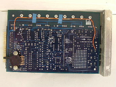 
MS back
[Edited on 24-8-07 by Chippy]
[Edited on 24-8-07 by Chippy]
|
|
|
DaveFJ
|
| posted on 24/8/07 at 02:46 PM |
|
|
to elaborate a little.....
It's a V3 board with an extra driver so it can run 2 sides of the Ford coil pack. Its set up as an MSnS extra....
cheers
[Edited on 24/8/07 by DaveFJ]
Dave
"In Support of Help the Heroes" - Always
|
|
|
paulf
|
| posted on 24/8/07 at 06:07 PM |
|
|
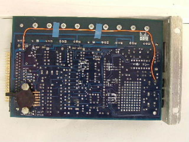
The above photo shows a V3 board the sensor is bottom left.
Can you attach a photo of your units PCB?
Paul.
quote:
Originally posted by DaveFJ
to elaborate a little.....
It's a V3 board with an extra driver so it can run 2 sides of the Ford coil pack. Its set up as an MSnS extra....
cheers
[Edited on 24/8/07 by DaveFJ]
|
|
|
Chippy
|
| posted on 24/8/07 at 06:30 PM |
|
|
The picture posted is of a V3 board, so you should just be able to add the MAP sensor. Don't know where you would get one though. Regards Ray
|
|
|
paulf
|
| posted on 24/8/07 at 09:08 PM |
|
|
I would be suprised if it had been built without a MAP sensor, they are available though from some of the suppliers listed on the main megasquirt
site, I have also seen them on Ebay ocasionally.
Paul
quote:
Originally posted by Chippy
The picture posted is of a V3 board, so you should just be able to add the MAP sensor. Don't know where you would get one though. Regards Ray
|
|
|
DaveFJ
|
| posted on 24/8/07 at 09:56 PM |
|
|
OK
hands up - I'm a numpty! Just removed the MS and had a lkook - the MAp sensor was staring straight at me - it even has 'MAP' written
on the case by the hole!
now I have given myself a new headache coz i have to refit it and it was a bitch to get out...
SO... does this need to connect to the 4 branch vacuum tube on the TBs?
cheers
Dave
"In Support of Help the Heroes" - Always
|
|
|
martyn_16v
|
| posted on 25/8/07 at 08:22 AM |
|
|
Ideally yes. If you're just using 'plain' alpha-n control (TPS as the only load reference) then it doesn't really need to be
connected as all the MAP sensor will be doing is measuring the atmospheric pressure at startup. However many people have found that they have more
success with hybrid control methods where the MAP is used in combination with TPS for load data, so you may well finding yourself wanting it connected
later down the road 
|
|
|
DaveFJ
|
| posted on 25/8/07 at 09:40 AM |
|
|
OK - think i have that sorted in my head now...
but what about questions 1 & 4 ? any more thoughts ?
cheers
Dave
"In Support of Help the Heroes" - Always
|
|
|
Chippy
|
| posted on 25/8/07 at 10:24 PM |
|
|
quote:
1. My wiring from the ecu has 1 wire for FI valve and 4 wires for IAC stepper. What do I need to connect to what? do I need to obtain one of these, or
both? If so how do they fit?
Not sure but I think as you are on throttle bodies, you can just forget the above items, nowhere to put them.
quote:
4. Where do I get the signal for my Tacho? there is no wire from the ecu for this....
Not sure with this either, as it depends on the type of Tacho, you may be able to take a connection from your coil, if running one.
Hope all the above helps. Ray
[Edited on 25-8-07 by Chippy]
|
|
|
martyn_16v
|
| posted on 26/8/07 at 08:28 PM |
|
|
1. You won't really need an idle valve, so just leave them disconnected and don't worry about it 
4. That depends on your tacho. If it can read a 12v signal then MS can be set up to provide a tacho output on one of the spare pins on the processor.
On the other hand if your tacho is designed to be attached to a coil negative then you'd have to connect the tacho to the coil triggers via some
diodes to get it to read correctly, if you google wasted spark tacho you should find what you need. On the other other hand you may have a fancy tacho
that can be set for a wasted spark installation in which case you're laughing
|
|
|


.jpg)