
Concern over front suspension.
Rorty - 7/1/03 at 04:05 AM
I was given a book token for Christmas, and to better understand what the Locost builders here are constructing, I ordered a copy of the BYOSC book
(second edition), which arrived today.
Now I've only skipped through it over a cup of coffee, and I'm already beginning to understand some of the problems and misgivings a few of the
members here have voiced.
I want to say straight away, that I do not want to step on any toes, or dishearten anyone already building a Locost. I have built quite a few cars
over the years from scratch, learning along the way, so I have a certain quantity of experience.
I have a few queries I would like help with. I hadn't realised to what extent the front suspension brackets are "floating". That is to say, they
aren't on a single plane, nor given a "hard" location. The surfaces of the chassis that the wishbone brackets are welded to are not on the same plane,
yet they must provide comon axis for the wishbones.
I don't have a problem with constructing that (I would make a series of accurate jigs), but I would never design a scenario like that for a DIY car
that novices would be building.
The book suggests bolting the brackets to a wishbone, offering the assembly up to the chassis, while keeping the axis parallel to the centreline of
the chassis!
IMO, that's virtually impossible to do accurately.
If the method described in the book for making jigs is the method most people have used to make theirs, then there isn't a hope in hell of the axis of
the wishbones being correct in the first place.
I appreciate the use of metalastic bushes is recommended, as they will tolerate a fair amount of misalignment, but rubber bushes are designed as shock
isolators which can deflect, not rotate. If true rotation is required, then some form of bearing (plastic or metal) is needed.
But if you fit needle roller bearings or use PU bushes, then they won't work at all because of the misalignment of the sleeves on the ends of the
(book) wishbones.
If you were asked to pass a length of 8mm silver steel rod through the top two brackets for example, how many of you could do it without resorting to
heavy hammer blows?
If said rod was indeed inserted through the brackets, would it then lie parallel with the base of the chassis (asuming there is no anti dive)? What
about the axis of the bottom wishbone brackets too?
Has anyone who has finished their locost experienced suspension bind, and to what degree?
How dificult did you find the construction of the front end?
Would you prefer an easier way to do it?
Another area that worries me is the actual suspension brackets themselves. They are perched on the chassis with quite a bit of overhang on the 1"/25mm
tube. With the "legs" of the brackets being unsupported, they will flex.
Has anyone with a few miles up in their Locost noticed any fractures around the wishbone brackets?
The book suggests tacking the entire suspension initially (I usually tack the entire car together before buzzing all the joints), and checking the
castor and camber before welding solid. What about checking for a square footprint? Even when I build a buggy in a jig, I always drop a plumb line
from datum points on the suspension to the floor (with caster, camber, toe set at zero), to ensure the car's footprint is square.
Has anybody ever modeled the front suspension to see what it actually does, statically, dynamically and in roll etc?
I can see where all the confusion and complaints of dimensions arise from!
Is our good friend, Jim McSorely's version enough, or is there a need for further plans?
Would it be of any benefit if there were separate, accurate imperial and metric plans?
There is a lot of talk about an independant rear suspension chassis coming up in the new book. If there is, then is it safe to assume it will be as
inacurate as its predecessors?
Does everyone buy their nose cone and body work, or do you mould your own, as suggested in the book?
Which raises another possibility. With some people choosing to fit the non "standard" Pinto engine (or any other tall engine for that matter), is
there a need for a taller chassis to accomodate taller motors?
Mr McSorely offers drawings for wider and longer (taller too?) chassis. Does anyone require more width, length or other options?
Even after only a quick glimpse at the book, I feel dissapointed. Not with the concept or basic design, but more with the manner in which some
critical areas are left wanting, and little or no guidance is offered.
I'm already thinking of redrawing the chassis both in imperial and metric units. I also would like to draw up some sensible jigs for making the
wishbones, and for positioning the brackets accurately on the chassis.
Has anyone got any suggestions regarding incorporating other features such as alternative suspension components, chassis dimensions...or whatever?

ProjectLMP - 7/1/03 at 05:05 AM
I am definately interested in techniques for accurately jigging suspension pickup points etc.
kingr - 7/1/03 at 09:43 AM
I'd be interested. I was planning on screwing four suspension brackets to a piece of thick MDF, and then using rod to hold the suspension brackets
that are going to be used on the chassis, then clamping the piece of wood to the chassis with the suspension brackets in contact with the chassis.
I realise that what I have just typed is perhaps not the easiest thing to understand. Anyway, hopefully provided the holes in my brackets are OK, and
I can fix them to the piece of MDF square (shouldn't be too difficult, and certainly a lot easier than doing it in 3D on different angled bits of
tube). It should also tell me if I need to shim the brackets at all.
Kingr
fastenuff - 7/1/03 at 06:55 PM
on the net there are some jig drawings for the front suspension, but even with those it seems difficult to get it all paralel. I've toying around with
the suspesion a while ( nothing definate though) also looking at the trackwidth alterations through the suspension movement.
For the suspension pick up points I.m considering the option Leitch has used, not using brackets like the locost but bolting through the chasis.
Mark Allanson - 7/1/03 at 07:00 PM
Rorty,
I made a jig to align the front suspension brackets, partly my own design, and partly a copy (I like the phrase 'inspired by') of something similar I
found on the net.
At work I have a Hunter 4 wheel alignment system which is computer controlled. All you do is put the sensors on the wheels and all the date is
displayed on the monitor, it measures eveything, caster camber KPI, track, thrustline, losenge. I will post a printout when I get to that stage!
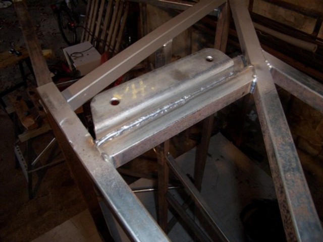
A image of 'my' jig
Mark

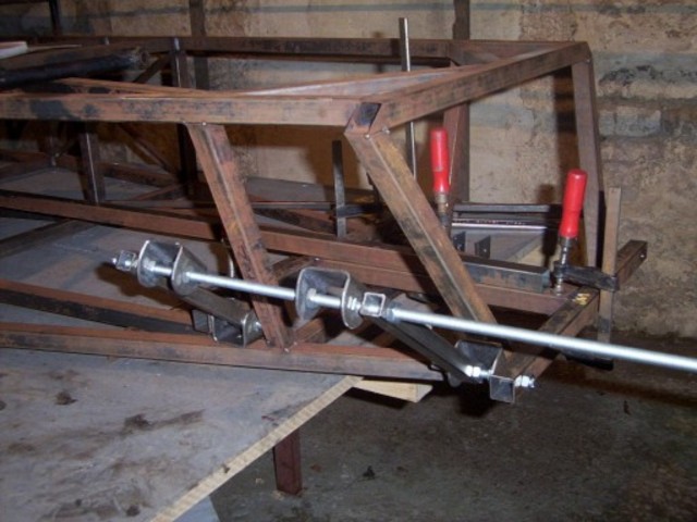
Rescued attachment DCP_0315sml.jpg
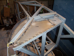
Mark Allanson - 7/1/03 at 07:03 PM
The jig pulled up to position, before this stage, I cut f*ck you1 and f*ck you2 out of the chassis and used the jig to set the position before welding
them in.

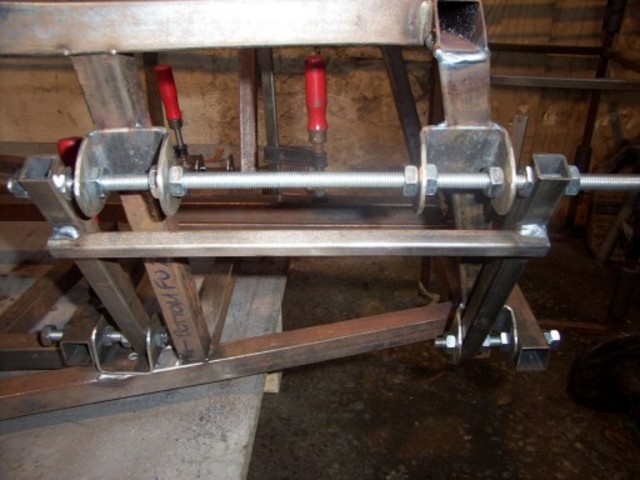
Rescued attachment DCP_0324sml.jpg
Alan B - 7/1/03 at 07:19 PM
Mine is similar, but different
Same princple....locate on the holes...
suspension bracket fixture
RoadkillUK - 7/1/03 at 07:21 PM
Merlin (wherever he is atm) made a Magic Box for the front
end.
Original Thread here
HTH
stephen_gusterson - 7/1/03 at 07:25 PM
Thing is Rorty, 1000s of people, inc those on this list, have built cars just like that!
I also reconed that the brackets are a bit wimpy. Its not just the fact they are on a 1 inch rhs - they are unbraced 3mm steel which I would like to
see even more stiffer.
On my car I ran a double section inch rhs and 50mm wide brackets, that were 'boxed' in at the sides.
As far as alignment was concerned as an amatuer I was well aware how hard it would be to get it all in line. Hence why I used adjustable everything
joints.
In my view there are a fair few bits of the car that could use extra gusseting. This is based on a lotus design after all - and lotus wer well known
for lightweight minimalist designs that killed people - Ask the first postumous world F1 champion.
atb
steve
geoff shep - 7/1/03 at 09:46 PM
I'm glad you've said all that Rorty. I got the book for Christmas and had similar reservations, but from an inexperienced viewpoint. One thing I
didn't understand was how the suspension bushes work - surely all the suspension movement (rotation) can't be provided by the rubber. Something must
rotate somewhere musn't it?
johnston - 7/1/03 at 10:06 PM
i remember seein somewhere pics of the trailing arm brakets fracturing so i asume the wishbone brackets would do something simiaer eventually
in regards to the bushes i was thinking of using something a bit more up to date than truimph so had a rummage round work and peugot 205gti or 405
wishbone bushes are almost the same size and i would say (but could be wrong) that a 405 would have a lot more wheel travel than a locost
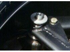
Mark Allanson - 7/1/03 at 10:15 PM
I saw the same or similar pictures, thats why I did this, you have me a little concerned about the fronts now!

Rescued attachment DCP_0274sml.jpg
stephen_gusterson - 7/1/03 at 10:47 PM
nice bracket mark and nice alignment system too.
The rear bracket still relies on the single rhs you have welded it to. If one end cracks then the rhs will come off with your bracket!
Lets not get too worried here - if lots of people were being totalle I think Haynes would have pulled the book!
I added extra gusseting and rhs where I felt things were critical on failure of a single part.
Regarding the earlier post about how bushes work :
The bush is a compliant plastic bush with a metal tube in the middle. The metal tube has the bolt through it. The tube pivots on the bolt, and the
plastic bit allows flex for alignment and shock absorbtion.
Your road car probably has them - or a version thereof - all over its suspension.
Make sure your welding is up to it is my main comment. A minimalist car like a locost has little structural redundancy in it. I added extra bits for
safety and cos Im not a professional welder.
atb
Steve
Rorty - 8/1/03 at 01:51 AM
Thanks all for the replies. I'm glad I'm not the only one whose hair on the back of the neck stood up after seeing some of the pics in the book.
Fastenuff, if you can remember where you saw the jig drawings on line, I would be interested in having a look.
Mark Allanson: Your's is probably the best jig I've seen so far. It is positively located to the chassis in at least two planes, so it won't move
while welding.
Allan B: I like the rigidity of your jig, but it does seem to be dependant on the accuracy of the location of two initial brackets. By the same token,
it doesn't register against the chassis.
I would envisage a solid jig that locates on the chassis, leaving absolutely no room for error. That's what I use on the buggy chassis. It makes
wishbone replacement (they are jigged too) a simple matter if one gets crunched or ripped off. (They do get ripped off on rocks etc from time to time,
and it's much less hassle throwing a few lengths of tube in a jig, and welding up a new wishbone, than having to cut-and-shut a damaged chassis.)
Merlin's composite front end: I had seen it before, but must admit I'd forgotten about it. I think it's absolutely foolproof, especially if there were
a couple of square cut outs to locate the chassis members (as someone pointed out...if you followed Roadkill's link). I would like to see it
lightened, and possibly made to accomodate as many other functions as possible..after all, if you're going to have the plates laser cut, you may as
well take advantage of the laser's accuracy, and add as many usefull holes/shapes as possible. I think given a bit more developement, and the accuracy
of laser cutting, that would be my first choice.
Geoff Shep:
quote:
One thing I didn't understand was how the suspension bushes work - surely all the suspension movement (rotation) can't be provided by the rubber.
Something must rotate somewhere musn't it?
Stephen Gusterson:
quote:
The bush is a compliant plastic bush with a metal tube in the middle. The metal tube has the bolt through it. The tube pivots on the bolt, and the
plastic bit allows flex for alignment and shock absorbtion.
Metalastic bushes are merely cast rubber tubes vulcanised onto steel crushtubes...160 year old technology! Sometimes they have an outer steel sleeve
too. The latter are horendous things to try and remove after they have rusted into the suspension component!
They should NOT rotate on the bolt, rather, the inner crush tube should be clamped securly in whatever sort of bracket or application they're being
used in. The rubber allows a finite amount of distortion, but they definately do not rotate, which is fine for lazy, heavy cars or trucks, but not the
answer for a lightweight, nimble sports car.
If you assemble a wishbone with those metalastic bushes, then bolt it into the chassis, so it's horizontal, it will remain in that position.
Granted, you could twat the end of it, and it will boing up and down a bit, but basically, you've got yourself an unwanted rubber spring addition to
your suspension.
You wouldn't find any of the roundy-roundy boys using them, as they hinder chassis tuning.
Im quite happy to draw up any useful additions for Locost builders, be they jigs, alterations or chassis conversions, but only if the demand is there.

interestedparty - 8/1/03 at 07:44 AM
There are two types of bushes in use as replacements for metalastik bushes-
Real polyurethane bushes- these work the same way as the metalastiks, the polyurethane itself flexes to provide the movement.
So-called poly bushes, often black in colour, very hard, no chance of this stuff flexing, they are supposed to swivel around the inner sleeve tube,
and the inner tube is supposed to be .2-.5mm longer than the assembled bush to allow for this movement.
In all cases, the metal inner sleeve is supposed to be clamped solid by the bracket. Applying some anti-sieze grease to the suspension bolt is not a
bad idea, but this is just an anti-corrosion measure
John
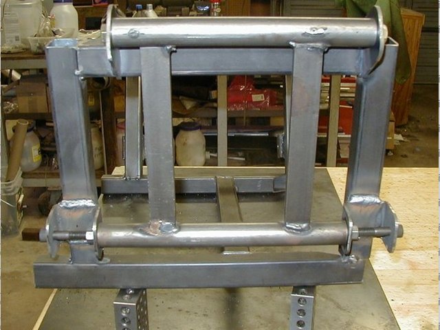
Mark Allanson - 8/1/03 at 07:57 AM
Steve,
The image is of the bracket in the early stages, but even then, the bracket is welded at the top, it extends up the slanted upright about 2.5" and is
fully welded.
It now has seat belt anchorages at the bottom extending 4" upwards and these are fully welded to fill the gap and then there is another filler panel
completely closing off - I will post a shot tonight to illustrate (at work at the moment!!) Shhhh
jollygreengiant - 8/1/03 at 09:25 AM
As Steve pointed, out the rubber bushes are and should always be thought of as "compliance " bushes and should be treated as such. When it comes to
final assembly you should always (where you have a bush) leave the suspension bolt loose until you have the vehicle fully built, loaded and on the
ground so that the suspension is fully loaded to nmormal running. THEN you should go round and tighten ALL the bolts. This approach will mean that the
bush only has to do its job, rather than try & allow all the suspension to align, thereby reducing the amount of stress that is tranfered to it and
the rest of the suspension.
Sorry if I'm trying to teach granma to suck eggs again. But some of the newbies might not be aware of the concept like the rest of you.
Enjoy.
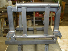
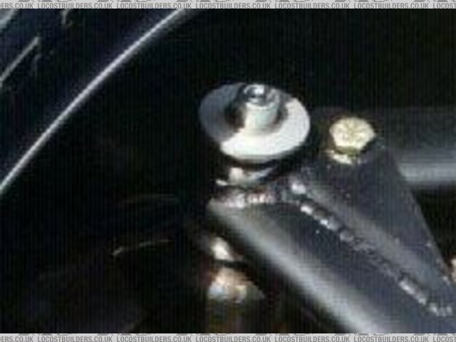
Mark Allanson - 8/1/03 at 06:44 PM
Steve,
As promised, the image of my reinforcements for the rear brackets (back at home now!!)
You can see the extra welds on the upper part of the bracket where it meets K2. I think the bracket would work even without M2, but I would not like
to try it. The seat belt mounts now do 2 jobs and the large filler plate (1.6mm) adds to the strength.

Rescued attachment DCP_0401mm copy.jpg
Alan B - 8/1/03 at 07:12 PM
quote:
Originally posted by Rorty
.........Allan B: I like the rigidity of your jig, but it does seem to be dependant on the accuracy of the location of two initial brackets. By the
same token, it doesn't register against the chassis........
Hi Bob,....not quite, it locates all 4 at once, but granted the lower 2 are clamped and measured from the bottom, by measuring the fixture that
is...not relying on the brackets themselves, just the holes (via the fixture).
I wasn't suggesting it was completely applicable for a "book" locost, just throwing in some more ideas. particularly the lower tapped bar to give
spacing and the 2 allen bolts to align the brackets, with the nuts to clamp the brackets.
I do agree with completely though about the shortcomings of the book...I use it only for occasional inspriation...never anything technical
darren(SA) - 8/1/03 at 07:27 PM

When welding my brackets on, I just threaded a 14mm rod through with spacers to ensure alignment which worked pretty well.I did the same with the
bottom only with bushes.getting them parallel to each other(looking from the side,I simply measured the distance between the rods on either side until
100%(I hope).looking from the top, well I took a chance, the segment that the brackets/bushes are welded onto/into is a perfect plane(my perfect not
an engineers perfect ). I'm sure all the engineers reading this are grinding their teeth at the moment but it seems to be OK,well we'll see on my
1st corner.
). I'm sure all the engineers reading this are grinding their teeth at the moment but it seems to be OK,well we'll see on my
1st corner.
Well enough of my waffling, my next concern is the bushes! I wasn't too concerned until reading the above posts:
We've got a company that specializes in rubber to metal bonding,rubber moulding and polyurethane moulding(you'd think I'd know whats going on) so I
would be able to make any bush nescessary.
First of all, all our bushes are made out of 90 shore rubber with an inner steel bush which was designed to rotate around the threaded rod.Now from
what I've picked up from you guys is that we must replace these with polyurethane bushes?
Do you think the Ideal thing to do would be to bond the urethane to the outer bush on the suspension arm with the loose inner bush? What shore
hardness should I use?
One thing i did not agree with the book is the suspension bolt diameter.If I'm not mistaken, I think the book says m8? We went m14 just to be safe and
will go m16 on the next one to be safer.Anybody else find this?
Ok my hands are sore and I'm sure you guys are yawning by now
thanks
darren
PS ignore the file at the bottom of the post. Please feel free to criticise my suspension as it is my 1st build and am always willing to learn!
[Edited on 8/1/03 by darren(SA)]

Rescued attachment lotus26.JPG
interestedparty - 8/1/03 at 08:44 PM
If you want to use polyurethane bushes, then they need to be resilient enough to provide the full required suuspension movement by the material itself
twisting. Given the choice I would go for the type which is designed to rotate around the inner steel tube (which needs to be clamped into position by
the brackets being squeezed closed by the suspension bolts). Most hard plastics can be used for this purpose, Jon Ison has used a type of nylon with
selflubrucatin properties, easily machined in a lathe. The important thing is that the inner tube be very slightly longer .2-.5mm than the assembled
bush. This is the type to go for, forget the polyurethane and the rubber, you don't need the hassle, and the type I have described have been proven to
work extremely well
John
stephen_gusterson - 8/1/03 at 11:11 PM
quote:
Originally posted by Mark Allanson
Steve,
As promised, the image of my reinforcements for the rear brackets (back at home now!!)
Yep. That would meet my idea of a bit of redundancy - nice idea!
Thanks also Rorty for clearing up my slight misunderstanding of rubber bushes. (I havnt used em!) Must say all the cars I have worked on have had
pretty 'springy' action on their bushes.
atb
Steve
stephen_gusterson - 8/1/03 at 11:18 PM
quote:
Originally posted by interestedparty
If you want to use polyurethane bushes, then they need to be resilient enough to provide the full required suuspension movement by the material itself
twisting. Given the choice I would go for the type which is designed to rotate around the inner steel tube (which needs to be clamped into position by
the brackets being squeezed closed by the suspension bolts). Most hard plastics can be used for this purpose, Jon Ison has used a type of nylon with
selflubrucatin properties, easily machined in a lathe. The important thing is that the inner tube be very slightly longer .2-.5mm than the assembled
bush. This is the type to go for, forget the polyurethane and the rubber, you don't need the hassle, and the type I have described have been proven to
work extremely well
John
One of the bush companies (polyflex???) have a website that says you can buy rod to machine your own bushes from.
The rod does not come with any centre hole or metal liner.
atb
steve
[Edited on 8/1/03 by stephen_gusterson]
Rorty - 9/1/03 at 01:37 AM
We seem to be back onto the topic of bushes, which myself and others ranted about on another thread.
DarrenSA:
quote:
One thing i did not agree with the book is the suspension bolt diameter.If I'm not mistaken, I think the book says m8? We went m14 just to be safe and
will go m16 on the next one to be safer.
8mm is fine, only if you're using metric 10.9 grade bolts (nothing to do with imperial grade 10). I would prefer 3/8" or 10mm just to add a safety
margin. No need for anything larger, unless you're using mild steel "garden" bolts, in which case you shouldn't be building a car.
Interestedparty:
quote:
If you want to use polyurethane bushes, then they need to be resilient enough to provide the full required suuspension movement by the material itself
twisting. Given the choice I would go for the type which is designed to rotate around the inner steel tube (which needs to be clamped into position by
the brackets being squeezed closed by the suspension bolts). Most hard plastics can be used for this purpose, Jon Ison has used a type of nylon with
selflubrucatin properties, easily machined in a lathe. The important thing is that the inner tube be very slightly longer .2-.5mm than the assembled
bush. This is the type to go for, forget the polyurethane and the rubber, you don't need the hassle, and the type I have described have been proven to
work extremely well
This was addressed in another thread, but now is getting a bit cloudy.
PU bushes are designed to rotate. Period. All PU bushes require a crush tube that is the exact length of the inside of the bracket it is being
mounted in. The softer grades (Shore 60 and Shore 70) when assembled, must be between 0.5mm and 1.0mm longer than the inner crush tube. In other
words, the crush tube is SHORTER than the (assembled length) bushes NOT longer, as Interestedparty states.
The reason for this is, the softer grades of PU will distort too much if made to the precise length of the crush tube, and will let the wishbones
wobble around. By making the PU bushes LONGER, they are preloaded, which resists compaction. They can be a real sod to install because they appear to
be too big for the gap!
When using the harder grades of PU, for bushes, they should be the same length as the crush tube. Before you go cutting or sanding the faces off the
PU bushes, find out from the supplier which grade they are. Even if they seem impossibe to squeeze into the brackets, they may well be the correct
size.
Nylon itself is not the best choice for bushes, as it is not classed as self lubricating. The modified Nylons such as Poltamides (PA) is a lot better,
and has good stiffness, lubricity, and good resistance to wear and fatigue.
The top of the pile though (for suspension bushes), is Polyacetal, or just Acetal (POM) and especially any of the variations that are combined with
Teflon fibres. The POM family machine freely too, unlike PU.
There are slippier plastics such as PETP, but they aren't as suitable for this application.
The main drawback for the average DIYer building a Locost, is that the harder bush materials are very rigid, and as Syd Bridge points out, don't lend
themselves to moving anywhere other than their designed axis.
So, unless you have attached your front suspension brackets with a jig, thereby ensuring the concentricity of the bushes on a common axis, there is no
point using either POM or Shore70/80 PU.
If there is any doubt in your mind as to the accuracy of your suspension brackets, just use the softer (more common) PU bushes, but don't use
Metalastic bushes.
This is all rather moot if the suspension design is unworthy. I reiterate one of my original queries, has anyone either modeled the book suspension,
or have any positive experience of driving a finished Locost? What, if any, modifications do the roundy-roundy boys make to their front end
set-ups?
I will glady model the book set-up, but not if everyone's happy with it as it is.

Rorty - 10/1/03 at 02:45 AM
Yes, and you can put turps in your engine too. It's a bit rough, but a lot cheaper than wasting your hard earned cash on expensive oil.

Rorty - 10/1/03 at 02:59 AM
If you want a really cheap alternative that does actually work and rotate as bushes are supposed to, turn them out of Oak or Beech.
In the last war, in the desert campaigns, both pistons and suspension bushes were occasionally made from wood (but for different reasons). The wooden
bushes would not allow the ingress of sand, which would chop out the crude rubber ones. Lignum Vitae was the wood of choice (South American timber,
densist timber known, doesn't float), but many species were used.
I've seen wooden bushes in use, and they worked perfectly. If you can get your hands on some old lawn bowls, they were made from Lignum Vitae .
Otherwise go for Oak or beech, stand them in oil for a week, and Bob's your mother's brother.

jollygreengiant - 10/1/03 at 10:21 AM
quote:
Originally posted by Rorty
If you want a really cheap alternative that does actually work and rotate as bushes are supposed to, turn them out of Oak or Beech.
In the last war, in the desert campaigns, both pistons and suspension bushes were occasionally made from wood (but for different reasons).
Some people still havn't forgotten the art. Not so long ago a mate of mine bought a Jag from the auctions. ran well for a couple of months & then
started smoking with a vengence. Took the top of & found 6 wooden pistons topped with tin plate.
just proves that theres's technicians & ----well!
------------------------------------------------------
Just to try & reinforce What syd just said, there was a case about a year ago of a man who restored a P5b rover coupe. He did a lovely job & it got in
to one of the national restorer mags. He said that he had not done anything to it that the average man in the street could not do & that he did it
himself. He even split the Rostyle rims down to ring & plate to restore them.
Fact - He ran a prototype Engineering workshop.
Fact - He got his his staff to do most of the work when they were not busy with orders.
Fact - How many competent Mechanics have the skill & competency to split a steel rim to it component parts & rebuild without making the unit
dangerous/unuseable.
I Am a technician & I would not strip a rim, personally I applaud all fellow members of this group who are building cars without the technical
background that I have. It takes a lot of self esteem to build something that others are going to inspect & condem or praise with little regard for
the skills of the person that built it.
Well done to ALL that have built & passed SVA/MOT. Let those be an example to the rest of us.
Enjoy
philgregson - 10/1/03 at 11:25 AM
The metalastic bushes we all use (if we use metalastic) are herald/spitfire wishbone bushes.
How were they utilised in the original application? - with the crush tube gripped or allowed to pivot and lubricated?
This should dictate how we use them - as they were originally designed to be used.
I dont see much of a problem with using them with the crush tube gripped if that is the correct way (and I think it probably is) - the front
suspension of a locost is stiff and has very short travel anyway. I'm lead to believe that this is how we get away with a less than optimum
design.
Just my thoughts on the matter.
Phil.
David Jenkins - 10/1/03 at 11:42 AM
quote:
Originally posted by philgregson
The metalastic bushes we all use (if we use metalastic) are herald/spitfire wishbone bushes.
How were they utilised in the original application? - with the crush tube gripped or allowed to pivot and lubricated?
I can only quote from the West field manual (to which we have some similarity )
They suggest leaving them to rotate for a hundred miles or so, until everything is settled and the favoured ride-height is set. Then the bolts are
torqued up to 30ft/lbs, locking the centre bit.
Personally I think it's a bit irrelevant as the centre tube has so little surface area at its end that it will rotate if it really wants to - although
I guess that the end of the rubber must be clamped as well, a bit.
rgds,
David
kingr - 10/1/03 at 02:26 PM
While I agree with Syd Bridges philosophy of if it works and is safe, use it, I feel that often many of us will not know whether something is safe
until it breaks. Using something in the way it was designed by skilled engineers creates fewer unknowns, especially when there's no obvious advantage
to using it in any other way. Just because you haven't heard of someone that has died/been seriously injured driving a locost doesn't mean they're
automatically safe.
While I reconize the incredible influence that "the book" has had, I do feel that by trying to conform to such a strict budget, corners may have been
cut, and it encourages others to do so too. What I think all of us should bear in mind is just what it is that we are undertaking, we are building a
high performance vehicle, which is not something that should be taken lightly. I don't intend to cause a flame war, I'm just putting accross my
philosophy of safety above cost.
Make sure your chassis and suspension is strong, make sure your steering and brakes are effective and build from there. I'll leave you to make
whatever conclussions you like about bushings
Kingr
Alan B - 10/1/03 at 02:33 PM
Syd,
I can't speak for Rorty, but IMO the bit that causes the cringe factor is not the principle, which is fine, but the application.
Regular bolts aren't very good for pivots, that's why the poly bushes have sleeves to pivot on.
An untightened bolt is not good either, even with a locknut as it can rotate freely and you would have no guarantee that the bushing was rotating on
the bolt.....the bolt could be turning in the bracket...making itself a nice little groove.
So in princple a rotating bush on a pivot is fine...it just needs engineering properly.
johnston - 10/1/03 at 07:39 PM
dont bout in england but over here in n. ireland if the bush was to pivot on the bolt and not twist the rubber you'd go home with out a certificate
not sayin its not good enough just that the poers at be wouldnt accept it
jollygreengiant - 10/1/03 at 11:09 PM
And for those of you not in the know, a METRIC bolt WILL have its grade of hardness/tensile strength marked on it as in 8.8, 10.2, 11.4, etc. This
also makes it easy to spot the difference between an imperial nut/bolt and a metric nut/bolt.
Enjoy.
Alan B - 10/1/03 at 11:27 PM
quote:
Originally posted by johnston
dont bout in england but over here in n. ireland if the bush was to pivot on the bolt and not twist the rubber you'd go home with out a certificate
not sayin its not good enough just that the poers at be wouldnt accept it
And therein could lie a problem.
No doubt in my mind that testers job is follow set down guidelines and use judgement in grey areas. It is not their job to evaluate a different or
unconventional design or unusal application of existing parts...as sound as the engineering may be.
They see a metalastic bush and look for clamping....or so it appears from feedback do far.
Any comment for those more familiar with SVA/MOT requirements.?
Rorty - 11/1/03 at 09:00 AM
Syd Bridge:
quote:
If there is a sound engineering reason why my previous comments regarding bush installation is unsafe, then he should bring it to our notice
now.
I thought the use and purpose of what I described was self evident and common sense, but I'll offer further opinion.
Any bush with a crush tube is designed to be fitted with the inner tube gripped tightly. There are no ifs, buts or maybes, they are meant to be locked
up solid.
How someone chooses to fit and abuse them is another matter.
The crush tubes, to the best of my knowledge, are mild steel, and are of a nominal diameter. A metal to metal bush would be made from alloy steel, and
the ID would be reamed to a precision fit. Merely slapping some grease around a bit of mild steel tube will not stop it wearing. Even if the bolt is a
12.9, the movement of the bush will not only destroy itself, but will oval the mounting holes in the brackets too.
That will result in a situation that not only belies the purpose of a sportscar, ie to have precise handling, but will also be bloody dangerous.
If you're just going to let the crush tube rotate on the bolt, why bother with the metalastic bushes in the first place, why not just run the bare
wishbones on the bolts with a smear of grease? At least the handling would be a little better, well, until the grease ran dry!
quote:
This method was used quite safely on car suspension systems well before Rorty was born, and is still used on trucks, so can't be too dangerous.
Metal to metal bearings have been around in one form or another since shortly after the wheel was invented. They were for extremely low speeds, and
were frequently of colossal proportions. More recently, trucks and heavy machinery have benefited from the passage of time, and use precision made
steel to bronze, or even steel to steel as
previously described. They are also of larger bearing area than the lowly Locust 8mm bolt!
Syd again:
quote:
While I'm here, how many degrees of steering movement left and right does this setup have? I haven't found a rodend with more than 13degrees either
way(give or take a degree), and most road cars are designed with 30-40degrees of steering movement in either direction.
If you're refering to the orientation of the rod ends in my uprights, they are capable of 38 degrees angularity. As stated, I modify standard 5/8"
rodends (most manufacturers' 5/8 rodends have the highest capabilities as standard).
I also stated I didn't recomend this approach, due to the relatively high cost of modification, but rather to orientate the rodends vertically, or
just use Transit trackrod ends.
Syd again:
quote:
I thought the aim of this forum was to help each other build roadgoing sportscars that were primarily economical and safe, and not marvels of the
professional competition car builder
I have offered nothing but help and advice, in this and other threads. The sentiment was to offer a cheap, light weight, easily made alternative to
the Cortina/Sierra upright which would also address some other people's desires to fit non standard wheels with incorrect offsets, and also offer a
simple method of quickening the steering without having to resort to expensive aftermarket racks.
The suspension components I use are not marvels, but are the same as are available to everyone else, from motor factors around the world.
Philgregson:
quote:
The metalastic bushes we all use (if we use metalastic) are herald/spitfire wishbone bushes.
See above.
David Jenkins:
quote:
They suggest leaving them to rotate for a hundred miles or so, until everything is settled and the favoured ride-height is set. Then the bolts are
torqued up to 30ft/lbs, locking the centre bit.
I would probably recomend leaving the bolts loose untill you get two people in the car, and push it up and down the driveway a couple of times, and
then pinching them up. After a hundred miles or so, a fair bit of wear could be caused.
I'm very surprised at them saying that.
Syd Bridge:
quote:
Industrial rodends were not designed to be used for automotive use, but do the job very well, and similarly other parts that we all use.
Define industrial and automotive rodends? You browse through the bearing catalogues, and pick out the ones that are rated for the job in hand!
Kingr:
quote:
What I think all of us should bear in mind is just what it is that we are undertaking, we are building a high performance vehicle, which is not
something that should be taken lightly.
Why not? It's only worth 250 quid. So what if the car kills someone!
AlanB:
quote:
Regular bolts aren't very good for pivots, that's why the poly bushes have sleeves to pivot on. An untightened bolt is not good either, even with a
locknut as it can rotate freely and you would have no guarantee that the bushing was rotating on the bolt.....the bolt could be turning in the
bracket...making itself a nice little groove.
So in princple a rotating bush on a pivot is fine...it just needs engineering properly.
Quite.
Syd Bridge, what a load of ambiguous clap trap, AND you've totally missed AlanB's point.
To finish it all off, you state:
quote:
I can't think of any more at this point. So, between you all, a solution has been hatched for a long time problem, which has probably been solved
similarly somewhere else in the past!
How pompous...how contrite....and a solution has not been hatched, you have totally pointed people in the wrong direction!
Syd, if your post is a wee take, or a retort following on from my "turps in the engine" dig, then please accept my appologies. Otherwise M8,
you're.............
Johston:
quote:
dont bout in england but over here in n. ireland if the bush was to pivot on the bolt and not twist the rubber you'd go home with out a certificate
See, the Irish aren't stupid!
Where's my whiskey? 
jollygreengiant - 11/1/03 at 11:42 AM
quote:
Originally posted by Alan B
quote:
Originally posted by johnston
dont bout in england but over here in n. ireland if the bush was to pivot on the bolt and not twist the rubber you'd go home with out a certificate
not sayin its not good enough just that the poers at be wouldnt accept it
And therein could lie a problem.
No doubt in my mind that testers job is follow set down guidelines and use judgement in grey areas. It is not their job to evaluate a different or
unconventional design or unusal application of existing parts...as sound as the engineering may be.
They see a metalastic bush and look for clamping....or so it appears from feedback do far.
Any comment for those more familiar with SVA/MOT requirements.?
Hmmmmmmm. Alan You really don't want to go down that road & open another can of worms do you?
OK then (this is my opinion & you must remember that it is in GENERAL terms only.) 4wotitsworth I am one of those MOT testers & have been for 7 years
approx. I am also the MOT QC for the depot at which I work (big clue - just AAsk).
From an MOT point of view I cannot think off hand of any reason for failing a suspension joint rubber bush for moving on its mounting. Unless the
movement was so great that it was liable to cause the vehicle loose control or be uncontrolable. To whit; eg Ford Mondeo front lower arms, inner front
& rear bushes cracked & badly split from their bondings. ( A VERY GREY AREA, TRUST ME).
The VI stance allways has been that these are PASS & ADSVISE, why because the arm cannot go any where because it has a large bolt & metal bush through
it which means that the arm cannot come out, there-by control, albeit poor will be maintained.
The big thing with MOT testing standards is that (In My Opinion) the were designed around a vehicle that was built in 1914 and very little account has
been taken for the development of cars since. could you imagine driving down your local dual carriage way/motorway/autobahn/freeway at speed in excess
of 50/60/70/80/90/100/110/120/130/mph in a 1914 whatever mobile. Most definately not but the general public still accept their annual mot certifcate
as a total overhaul/service/inspectionroad worthyness certificate for the next 12 months. Mind you I believe that in Aus the test is only required
when you sell the car!.
Anyway everyone, Yes the book does have inumerable short commings and suspension is a very important factor, just as much as the brakes and judging by
the standard of driving around the Rushden Race Track (steve will Know what I mean) the Idoits/driver behind the wheel. Remmeber its not the car that
kills but who is doing what when the incident happens.
As for bushes MOST people who get behind the wheel of a car would not notice / appreciate / benefit from changes to the types of bushes used AND for
the most part the metalastic bushes will be Quite Addeqate for thew job in hand. unless of course you drive like hicost. Then its horses for
courses.
Enough said Lets all be friends & HELP each other.
Enjoy
If I've upset anyone Im sorry & all spelling /grama mystooks r itensional
johnston - 11/1/03 at 08:27 PM
no offence jolly but ive worked on cars that have come over the water with english mots
and if you took it to a northern irish one it would have a list as long as your arm
if rorty has left to oz within the last ten or so years he'll bac this up every mot is like a sva
only the guy doin the check is usually bored in a foul mood pissed off gettin muck fallin on his head and doin 12 hour shifts all for shite money
i have seen them fail brand new tca's track rod ends
put sharpened bars through floors
fail cars for having rusted flarenuts on brake pipes
there is also a new computer test which i havent had the pleasure of doing yet
if u have a diesal u have to sign a disclaimer incase they blow up your engine when doing the gas test
when the first computerised centre re opened after conversion seven brand new cars straight of tghe transporter went through the test after complaints
they were to strict; 2 passed
jollygreengiant - 11/1/03 at 11:30 PM
I cant comment on the new computerised test yet as we are still waiting for it over here. As reguards the standard of testing I was talking about the
test standard as laid down by the VI & as I/we have a local office not far from where I work we tend to get regular visits. Oh & I have witnessed VI
staff doing things that I Have got B*ll*ckings for from a roving inspector. Yes they are trying to pull up standards but with the no striping of
parts policy and new motors coming out with so much underside / engine / wheel arch paneling fitted so that you can not see at all (new 7 serries BMW)
what you need to be looking at. AND TOTAL FLY BY WIRE brake, tranmision & engine control It makes things interesting. Then you've got top line audi,
porche, mercedes which come with a dealer only key to open the bonnet so they MUST be refered back to the dealers (who don't really want them cos they
are over the 3 year age barrier).
So jolly old MOT testers are meant to write out tickets for things that they can't see.
Also it wasn't that long ago that I met someone who had come over from Ireland with a FULL uk Licence. Never took a test got the licence cos they had
had a provision licence for a moped for 8 years & with the testing backlog they held an amnesty & issued licences to those who had held provisional
licences for 6 years or more!
Times are a changing as is the everything in life. We all try & do the best we can given the limits that we are allowed to work in. Personally I am
totally digusted with the leniency with wich we meant to treat the mechanical condition of vehicles & the lack of backbone by those in power to say to
those testing that if a component is Nadgered as in my case with mondeo wishbone bushes then tough Sir/Madam IT FAILS! The trouble is that customer
think that the MOT is more than it is. Then you have the tyre wear laws. MOT law is one thing, construction & use laws are another, also if the
vehicle is a van does it come under car or commercial tyre wear. There is no cominality in the regulations. Personaly unless your on a race track I
think that 1.6 mm not enough.
Sorry I rattled on again like my daughter.
We all have relative experiences & through those we can help each other.
Enjoy.
johnston - 12/1/03 at 06:09 PM
quote:
licence cos they had had a provision licence for a moped for 8 years & with the testing backlog they held an amnesty & issued licences to those who
had held provisional licences for 6 years or more!
yeah that would have been down south thou theyve only just introduced an mot style test and from wat i can gather its only done every other year
not 100% sure if this is true but ive been told you dont need a qualified driver beside you if your on a provisional therefore you dont actually need
to do a test to drive
was told of a ren4 a student brought to belfast left it into a garage for a service the car was that bad the copper brake pipe burst as the mechanic
was parking it outside
jollygreengiant - 12/1/03 at 08:20 PM
When I was working in Bedford for another company (L*X) a few years ago an old gent bought a car (Fiat127 I believe)
in for MOT & as I jacked at the front it started to give in the middle due to corrosion ------- Test suspended & customer advised. He still decided
that he had to drive it away!
Also a firm called G***iner M**ors out of Wellingborough (I might have been working for him {allegedly} at the time)
had his recovery truck tested by the ministry. After it passed (thats another story) his son collected it & litteraly drove it 100yds back to our
depot & stops. As he does so, A brake pipe fails. Wots the boss do (sorry but he IS Irish), phones the VI & gives THEM a B*LL*CK*NG the likes of which
I never heard before.
Next year the VI (same bloke) MOTs the wagon again. ------- 3 guess's wot he failed it on.?
"brake pipes corroded" & that was all he wrote on the VT30. Boss starts to ring & complain so I says remember last year. so he says "but which
pipes".
Reply came "ALL"
Moral of the story don't P*ss *ff the ministry.
Enjoy.
Rorty - 13/1/03 at 04:05 AM
Monday, back again. I'll address the remarks as they come.
Syd Bridge:
quote:
It seems some emotions are getting a bit hot.
I think I was more exasperated than hot. I would be the last person to claim my way is the only or right way, but I do get pi$$ed off when someone
arrogantly states they have hatched THE solution to a problem when clearly the book is still open. Moreover, I still maintain some of Syd's notions
are ill founded, and his statements border on reckless and iresponsible. Some novices could take what he stated as gospel, and create a potentially
dangerous vehicle as a result.
quote:
AlanB's comments are level headed, relevant and straightforward.
I have nothing but the highest regard for AlanB. I wouldn't know him if I fell over him, but the impression I get of him from his professional,
amiable posts, to the sterling work he's doing on his car, could only lead me to hold him in high regard.
I was not leveling any complaint or critisism at AlanB, but at the manner in which Syd Bridge misrepresented what AlanB had said.
Syd again:
quote:
When is a metal tube in a bush a 'crush tube', and when is it not?
For crying out loud Syd! Any metal tube in a bush is a crush tube is a crush tube is a crush tube is a crush tube! They are designed to be nipped up,
captured, squeezed, whatever. They are for resisting crushing forces, to keep any surrounding material from being crushed or distorted to the point
where they become inoperable or fail.
Any other bit of tube is just that!
Syd again:
quote:
Rorty, please read what I said previously again. If necessary, go and run your eyes over some earthmoving and agricultural equipment, then down scale
some of the solutions you see. Your racing machinery might even benefit.
Not only are you pompous and arogant Syd, but now you're patronising me too.
I'm perfectly aware of heavy indrustrial and agricultural pivots, and if you read what I said, you would have seen that I payed hommage to them.
Syd again:
quote:
The Quinton Hazell part comes in a box marked part no.Y419. The box contains rubber bushes that have integral metal liners.
Crush tubes?
quote:
The box does not say' Triumph Suspension Bushes with crush tubes'. These and similar bushes can, and have been used for many applications, apart from
suspension bushes.
They can be found in many places where some flexion is called for.
Has anyone got a workshop manual for a Spitfire/Herald, or any old cars which used Metalastic bushes? What are the installation instructions for
them?
Syd again:
quote:
The solution arrived at here, may not be the one you accept, but then again, I'm not trying to say that this is the ONLY, or best solution.
Here we go again! Syd, it's not "the solution", it's your opinion, and an illadvised one at that....in my humble opinion, that is.
Syd again:
quote:
Rorty, I am genuinely interested to see how you achieve near 50% more rotation than manufacturers spec with your rodends, as your frontend pics don't
show any appreciable modification of the joint. This would solve a myriad of worries for most people here, as to future options.
Syd, you're quite the protagonist! I won't be drawn on this one. I have already stated that I don't believe it is the way forward for Locosts, due to
the cost of modifying the rodends. The rodends would be perfectly serviceable orientated in the vertical plane, which would keep costs down.
Alternatively, Transit, or similar, trackrod ends could be used.
Besides, I don't want to divulge all my secrets! Suffice to say, I get ample articulation out of them, with abundant travel too.
Syd again:
quote:
Don't look for problems, look for answers!
Sheeeesh!
Jolly and Johnston, I can't really comment on current MOT and SVA tests, as indeed, I left the UK in 1992, but prior to that, I had my fair share of
run-ins with testers.
I would just like to round up by saying that my offers of help are genuine, and I will be only too happy to assist anyone in any way I can. I don't
profess to know it all, or even half of it. I'm a furniture restorer afterall.
I really enjoy this open forum, and if any of my comments have anoyed, outraged, or offended anyone, then again, I appologise.
Syd, I sincerely wish you "G'day". 
Metal Hippy� - 13/1/03 at 04:22 AM
Hopefully from my point of view as an innocent bystander this is over with now?
I've followed the 'arguments' the last few days and mostly there's no point to it as Rorty at least knows. It gets nowhere and causes annoyance,
frustration and stops this being a forum that's as fun as it is informative which I think most will agree is a fair percentage of the reason it's
become a success.
All agree?
jollygreengiant - 13/1/03 at 10:05 AM
Just one thing that annoys me, Rorty ------ where do you get your smileys from. (appart from the VI that is)
God its another day & the chances are inumerable ------ Enjoy.
If it seems like Im having a pop at anyone then Im sorry (except for the VI) cos Im not, Just telling a line or two as they are from my eyes 'n' ears
& listenening to the sound of posts that come back.
[Edited on 13/1/03 by jollygreengiant]
philgregson - 13/1/03 at 03:28 PM
Sorry - I know we should be letting this die but I just want to have one last say.
If you are using metalastic bushes they should be used as designed i.e. clamped tight on the crush tube - the application here is almost identical to
their intended use in a spitfire or herald. What is the point of using them in any other way when this is what they were designed for?
If you do not want clamped up metalastic bushes then use something diferent that is designed to act as a rotating bush or pivot. If something readily
exists to do a job then why are we spending hours debating how to get away with something less suitable.
If you want nylon bushes but can't afford them there is no excuse for bodging something not suitable when there is an acceptable, alternative, cheap
and perfectly functional way of doing it (clamped metalastic bushes).
Just my humble opinion.
Phil.
stephen_gusterson - 13/1/03 at 08:32 PM
quote:
Originally posted by jollygreengiant
Also a firm called G***iner M**ors out of Wellingborough (I might have been Enjoy.
Ahh, jollygreen, mr gardiner. He used to do all the servicing on my companies cars 10 years back. I have also used him on two occasions to recover
cars - one got hit at the side of the road, the other was my donor!
Gardiners dont do mot's - they farm em out. Sanders motors is run buy a good olde boy 400 yds up the road - they do mots and seem to be fair. Perhaps
he should have used them!
The crappyest garage I ever dealt with was the rover garage in wellyboro - now defunct. Here are just a few peices of fun with my F reg 820E rover
(when it was 1 - 4 years old - flywheel eventually came loose and wrecked the engine - and was bought by gard.......)
1. Car overheats thro lack of water on way home from service. "Service does not include water check...."
2. Front disks are scored by worn pads. "How come you didnt replace pads at 12,000 mile service' - answer - we check that the pads will last to the
OPTIONAL 6,000 mile service.
3. Brake light warning comes on. "I think the back pads are worn' - 'ok - we will look'. "nothing wrong sir - loose wire. Light comes on again. "we
think its a wiring loom fault, bring it back in a couple week s when we have the part." Loom fitted on 3rd visit. Driving car home, light comes on
again. Take car back, 4th time, not best pleased. "we found the fault sir. Rear pads were worn.
Total, total total, total, total W A N K E R S.
Had 3 garages, all gone now. Wonder why.
This thread is getting petty.
How about finding my ABS thread and resurrecting that for a laff
atb Steve.
Rorty - your advice and knowledge is well appreciated.
Syd - wish you well in your car builds and thanks for stimulating the discusssion which has taught me a bit along the way.
atb
Steve
atb
Steve
[Edited on 13/1/03 by stephen_gusterson]
Rorty - 14/1/03 at 12:54 AM
Hi Chaps.
Beautiful day down here...37 degrees. It's too hot for any serious work, so I'm off to turn some crush tubes for the PU bushes I've got to fit
tomorrow. 
fastenuff - 14/1/03 at 06:48 PM
you could make me some Rorty but in such a way that they hold some Lite Ice and spill the VB
ingmar
stephen_gusterson - 14/1/03 at 11:02 PM
respectfully, and in no way wanting to cause an argument but....
I was confused here.
Crush tube sounds like its gonna deform and get shorter and even pinch the bolt. Is this what you are describing?
Otherwise, in my vocabulary, this sounds like a spacer. One thats a mil or so longer than the bush, that is clamped and held from rotating and stays
1mm longer than the bush.
Is this a terminology thing or does it really reduce in length - i.e crush?
atb
Steve
Rorty - 15/1/03 at 01:45 AM
Steve:
quote:
Crush tube sounds like its gonna deform and get shorter and even pinch the bolt. Is this what you are describing? Otherwise, in my vocabulary, this
sounds like a spacer. One thats a mil or so longer than the bush, that is clamped and held from rotating and stays 1mm longer than the bush.
This is just terminology. A crush tube doesn't get squashed or buckled, quite the opposite. It is to resist crushing loads. Another instance of a
crush tube, is the short length of tube you would weld through a chassis member through which you would insert a bolt for the likes of a seat belt
shackle. In this case, the crush tube prevents the seat belt bolt from crushing the surrounding chassis member.
As described earlier, a crush tube for a soft-ish PU bush, needs to be about 0.5 to 1mm SHORTER than the assembled PU bush. A crush tube for a hard PU
or Acetal bush needs to be the same length, and the crush tube that comes Vulcanised into a Metalastic bush, is generally LONGER than the rubber bush
to reduce side friction when the bolt is tightened.
Amen?
stephen_gusterson - 15/1/03 at 10:16 PM
thx Rorty. That clears things up.
So....
if I decide to get some special bushes turned out of a length of polyflex supplied pu(?) I need tubes thro it that are 0.5 - 1mm shorter.
This might also explain another problem.
On my car, I have some zeemeride chepo shocks. without tigtening the top and bottom bolts, or using side washers on the rubber looking bushes, they
are being very deformed. I guess that with washers each side of the crush tube, this will support the rubbery bit and prevent this distortion?
atb
Steve
Rorty - 16/1/03 at 12:34 AM
In that particular instance, I would leave well alone. Those shock bushes are a prime example of where a rubber/Metalastic bush actually performs
within its limits.
The deflection of the shock during wheel travel is a lot less than the wishbone pivots typically see. Therefore, the bush merely flexes, and the
rubber is man enough for the job, as rotation of the shock eye around its mounting bolt is minimal.
The reason rubber shock bushes wear out quickly is more to do with their diminutive size, and the pounding they take, rather than anything to do with
being torn apart by rotational force.

kb58 - 21/1/03 at 04:10 AM
Back to the original topic. The way I did it was by building it in reverse. That is, I built up a fixture which held the suspension arm rod-ends at
the exact points in space relative to each other. The fixture was then "offered up" to the chassis and fixed in position. The beauty of that is you
then simply build brackets out from the chassis with bolts already passing through the rod-ends. That way you know for SURE that it's exactly where
it should be.
stephen_gusterson - 21/1/03 at 08:13 PM
whatever happened to lasermans great idea of a pre manufacured weld on box type front end with brackets attatched?
atb
steve
Mark Allanson - 21/1/03 at 09:20 PM
The weld on box would be only as good as its fitment. Have a peep at "castor angle" in Running Gear so see the accuracy required to maintain the
castor angle.
dougal - 9/2/03 at 11:45 PM
im not getting involved in the argument but from my point of view as an engineer is that if you are going to let the tube rotate around the bush the
make sure that the bolt outer to tube inner clearance is very small or else any slop will allow the sleve to machine the bolt causing stress raisers
allowing cracks in the bolt.
im not sure what im gonna use.
jcduroc - 26/2/03 at 11:45 PM
quote:
Originally posted by Rorty.
... Another instance of a crush tube, is the short length of tube you would weld through a chassis member through which you would insert a bolt for
the likes of a seat belt shackle. In this case, the crush tube prevents the seat belt bolt from crushing the surrounding chassis member.
...
Rorty
How would a front wishbone mounting be, IYO (in your opinion), crossing the chassis member tube?
Jo�o
Rorty - 27/2/03 at 03:34 AM
IIUYC (if I understand you correctly)  There's no reason why that can't be done in
theory. I've seen both Rose joints and studded brackets mounted through chassis members before. Obviously, the hole in the chassis member would need
to have a crush tube welded in.
There's no reason why that can't be done in
theory. I've seen both Rose joints and studded brackets mounted through chassis members before. Obviously, the hole in the chassis member would need
to have a crush tube welded in.
The problem with mounting a Rose joint in such a manner, is the short amount of thread. It is surmountable by using a 2X adjuster in the chassis,
which means the Rose joint is infinitely adjustable, and never needs to be removed for adjustment. The weight penalty and extra components/machining
may render it unsuitable for all but the racing 7esque Locosts though.
The glory of mounting everything through the chassis is, initally, you just have to drill some 19mm holes, and weld in the crush tubes. After that,
all the brackets can be bolted in. A neat trick would be to position the studs on the back of the brackets off centre, so by rotating them 180
degrees, you would have a different amount of caster.
If any other dimensions needed to be varied at a later date, new brackets with suitably off-set studs could be inserted.
Is that what you meant, or have I totally missed the mark? 
Fast Westie - 27/2/03 at 10:51 AM
quote:
I've seen both Rose joints and studded brackets mounted through chassis members before
Caterham do this quite regularly, even in the wishbones.
jcduroc - 27/2/03 at 10:57 PM
[quote There's no reason why that can't be done in theory. I've seen both Rose joints and studded brackets mounted through chassis members before.
Obviously, the hole in the chassis member would need to have a crush tube welded in... The glory of mounting everything through the chassis is,
initally, you just have to drill some 19mm holes, and weld in the crush tubes... Is that what you meant, or have I totally missed the mark?
What I mean is something like this (apart from the very poor drawings, just done them on the spot/over my knees)
[img]Cocuments and settingsadministratormy documentsmy picturesFrSuspWishboneWithUNIBALLOnChassisTube.gif[/img]
or this, with bushes
[img]Cocuments and settingsadministratormy documentsmy picturesFrSuspWishboneWithPolybushOnChassisTube.gif[/img]
what do you think?
Jo�o
jcduroc - 27/2/03 at 11:05 PM
[img]Cocuments and settingsadministratormy documentsmy picturesFrSuspWishboneWithUNIBALLOnChassisTube.gif[/img]
or this, with bushes
[img]Cocuments and settingsadministratormy documentsmy picturesFrSuspWishboneWithPolybushOnChassisTube.gif[/img]
what do you think?
Ignorant I am, pictures do not show up, so I uploaded them to my Photos area (jcduroc)
Jo�o
Rorty - 28/2/03 at 12:26 AM
OK, I totally misunderstood you. What you're illustrating, is actually a wishbone pivot, mounted in "single shear" i.e. it has a shear path in just
one place, as opposed to the more common double shear bracket, that supports both sides of the pivot.
I certainly wouldn't recommend a single shear mount for the lower wishbone, as it is quite highly loaded, however, it would be suitable, though not
ideal, for the upper wishbone mounts.
You would have to ensure the crush tube has a wall thickness of at least 3mm, and is correctly positioned. Needless to say, you would want to use a
grade 8 imperial bolt, or a 10.9 metric bolt, and observe the correct torque figures when tightening.
A fail-safe washer would also have to be used. A FS washer is to prevent the wishbone eye coming off the bolt in the event the bush fails. The same
goes for any type of pivot mounted in single shear. The washer would need to be about 10% larger in diameter than the wishbone eye, and not less than
3mm thick. See attached pic. 
Rescued attachment fail_safe_washer.jpg
fastenuff - 28/2/03 at 06:53 PM
hi ya Joao
have a look at: http://www.freshairmotoring.com.au/
think this is what you are looking at
jcduroc - 28/2/03 at 09:30 PM
quote:
Originally posted by fastenuff
hi ya Joao
have a look at: http://www.freshairmotoring.com.au/
think this is what you are looking at
Hi Ingmar
Is this what you mean?
Jo�o
Rescued attachment LeitchFrSusp.gif
Rorty - 1/3/03 at 05:58 AM
Joao, whoever built that car has mounted everything in single shear, includind the shocks. It's not exactly going to fall apart though, all those
bolts look like they're 12mm or even 16mm!

fastenuff - 1/3/03 at 03:35 PM
yep thought that was what you were talking about.
Rorty
this chasis is a commercial chasis build in Melbourne, OZ or New Zealand. they must be doing something right selling their cars.
jcduroc - 2/3/03 at 01:16 AM
Ingmar
This is Leitch, origin NZ, also sold in AU.
Rorty
Had a look at the amazing wheel inset? And the amount of scrub radius it has?
Cheers
Jo�o
Rorty - 2/3/03 at 01:28 AM
Joao:
quote:
Had a look at the amazing wheel inset? And the amount of scrub radius it has?
yes, I moticed that too. It must be around 150mm! 
They obviously feel, being such a light car, it warrants that amount. Either that, or it handles like a
pig!
kingr - 2/3/03 at 11:05 AM
I looks like they've put the wheels on backwards!
Kingr
cymtriks - 2/3/03 at 05:43 PM
Superb triangulation compared to most kit car chassis if possibly a bit overweight. The lower wishbone of the Leitch, and Caterham, appear to be in
single shear mounts. The lower wishbones carry roughly double the loads of the upper wishbones so if it's OK for the lower ones it should be good
enough all over.
jcduroc - 2/3/03 at 06:47 PM
quote:
Originally posted by kingr
I looks like they've put the wheels on backwards!
Kingr
Judging from the cycleguards stays it seems so!...
Jo�o
Rorty - 3/3/03 at 05:42 AM
I think it's time we put this joke to bed, and stop mucking about, in case someone sees that pic of the Leitch, and reads this thread, thinking it is
alright to build their car with that amount of offset/scrub radius.
THEY HAVE DEFINITELY PUT THE WHEEL ON BACKWARDS for clarity, when they wanted to show off their suspension.

Duncan - 3/3/03 at 08:33 PM
If you look closely at the wheel on the right side of the picture you can clearly see it is on the wrong way round.
Maybe its time to put this whole post to bed?
I think all that can be said, has been said, although no doubt one of you will have something else to say?
craig1410 - 5/3/03 at 12:23 AM
Hi,
Must be one of the longest threads in history...but there was a point to it once which is why I've just read through it, trying to find the answer!
Question I have is regarding the orientation of tubes LA and LB. I have welded them so that the front faces of LA and LB are parallel to the lateral
axis of the car. (ie. Front faces of tubes LA and LB in same plane)
However, that means that, due to the inclination of the front assembly, the outside faces (where suspension upper front mounts attach) of LA and LB
are not parallel to the longitudinal axis of the car which seems wrong to me because the suspension mounting will then not be in line with the
longitudinal axis either. I'm sure I could pack out the bracket to suit but surely that can't be right either.
Basically I can't see how the front face can be parallel to the lateral axis and the side face parallel to the longitudinal axis at the same time with
an inclined front subassembly.
Which way should it be aligned? The book doesn't seem to be very concerned about this and the pictures are inconclusive.
Thanks for any help you guys can give,
Craig.
davef - 5/3/03 at 06:32 AM
Hi Craig do yourself a favour and fit and tack weld LA&LB in situ on chassis, it,s a lot easier & do as i suggested to Hornet.
take 25mm out of the top tubes & lean LA&LB further back for a more favourable positioning of front top wishbone brkts. also when positioning LA &LB
place a straight edge on the outside plane & measure equally from the straight edge to your marked centre line which your chassis must be set to. that
way you know your brkts will be in the correct plane.also leave FU1&FU2 out untill your front top brkt is set along with the bottom brkts. to make it
easier get youself two pieces of MDF and mark out the configuration on page 63 doubling the horizontal measurments of course, now drill out the marked
out holes to the size of bolts you are using, get four lenghths of threaded bar the same size, and numerous nuts to position all the brkts , and offer
this to the chassis. when all is set, you can now place FU1&FU2 against the top rear brkt which is being positioned by the top front brkt held togther
with the threaded bar having removed the lower threaded bar. i hope all this makes sense to you, anyway it,s how i did mine, cheers davef.
craig1410 - 5/3/03 at 07:54 PM
Hi Dave,
Thanks for the tips. You have confirmed my suspision that it is the edge plane that should be parallel to centreline rather than the front plane
parallel to the lateral axis. Looks like I'll have to go and cut out my tack welds and make a fw adjustments. I wish the book made this point clearer
because it seems to me that this is fairly important!
Cheers,
Craig.
pinyachta - 31/3/04 at 09:07 PM
The Spitfire bushes are pressed into the control arms with such interference they cannot rotate. The bolts generally set up in the sleeves and
can't rotate either. Usually a torch is necessary to remove them. The bolts are 3/8" high strength steel torqued to maybe 25-30ftlbs..
The rear bushes on the Toyota trailing arms actually have teeth at the ends of the sleeve to eliminate any rotation.
jbmcsorley - 31/3/04 at 09:36 PM
Hi Rorty,
To address one of your original comments... that the uprights are not coplanar...
I've worked out a revised front end design that results in the front uprights (LC/LD and FU1/2) being parallel and co-planer. This allows the
upper wishbone brackets to be positioned anywhere along the outer face of the upright tubes.
I shared this revised design with a few builders that I've collaborated with in the past. Based on their feedback, it does greatly simplify the
installation of the upper wishbone brackets. It also affords the opportunity to use standard stock-car racing parts (like upper cross-rails) right
out of a catalog.
Here are some examples so you can see what I mean:
http://texaslocost.homestead.com/Suspension.html
http://www.geocities.com/isogriffination/
Perhaps this is more like what you had in mind, Rorty?
Does this redesign qualify me to publish my own book?
Cheers,
Jim McSorley
[Edited on 31/3/04 by jbmcsorley]
britishtrident - 31/3/04 at 09:38 PM
I am sorry to be rude but I am going to come down heavy.
Bull sh*t -- no spacframe is ideal ie feeds all the loads into nodes, yes the detailing of the front and rear suspension brackets is less than
ideal particularly the attachment points for the coil overs but thats life, the book chassis is more or less a carbon copy of a a pre-lit Westie so
if you add up all the Westies and Locosts built that is a heck of lot cars some of them with truly daft oversized engines that work pretty well.
The metalastic bushes used were designed precisely for the jobs they are used for (they are actually wishbone pivots on Triumphs), Lotus used similar
bushes with even less rubber on the Chapman era roads cars without problem. They were also used by many older cars and commercial vehicles as leaf
spring eybushes I have never seen any bushes of this type cause problems or fail when used as they are in the Locost.
The book has serious faults but these ain't them.
[Edited on 31/3/04 by britishtrident]
jbmcsorley - 31/3/04 at 10:11 PM
sorry about that britishtrident,
I didn't mean to pass judgement on the quality of the spaceframe... I was refering to the complexity of the front end by suggesting that it might
not be 'ideal' for a DIY builder. This is based on my having talked to well over 50 other builders about this very subject.
If you take a look at the links I provided, as well as the results of my having studied the locost chassis for nearly 3 years (on my website), I think
you'll find that my comments were intended to be constructive.
I'm quite familar with the faults in the book... it wasn't my intent to stir this already heated subject. sorry for that.
-Jim McSorley
Orland, FL, USA
http://mcsorley.net/locost
derf - 31/3/04 at 10:11 PM
WOW this thing was dug up from the dead. I thought I read back far (about 6 months worth of posts, but this is from March of 03 a whole year.
As far as metalistic vs poly vs rubber bushings, metalistic is best, it will give the most firm and controlled car, rubber will be more compliant and
it will allow the suspension to move (these are small so I'm sure the difference wont be that bad), and poly bushings are somewhere in the
middle, I bought a few poly bushings the other day (supposed to be $128 worth, paid $20), and they came with metal sleves. As far as my understanding
of bushings is that they dont rotate (not supposed to anyway), the steel inner tuber rotates around the bolt which passes through. I'm no expert,
but every time Ive seen a suspension bushing that is how I thought it worked. When I do my suspension I fully expect to make the A arms, then make a
jig like on page 2 or 3 and then I'm done. Yes the book is less than specific about this (waiting for 3rd edition) but that's why people
like me look to others for inspiration and ask questions....
JoelP - 1/4/04 at 08:04 AM
well derf, i dont think anyone will be bothered to argue anymore! people can just read the thread and decide what they believe.
But mine will be pinched tight 
[Edited on 1/4/04 by JoelP]
Peteff - 1/4/04 at 08:48 AM
Unless your brackets are very thick steel or you don't tighten your bolts you will find that the bracket will grip the crush tube and the
polybush will rotate round it when the suspension is asembled.
James - 1/4/04 at 09:52 AM
quote:
Originally posted by JoelP
But mine will be pinched tight
[Edited on 1/4/04 by JoelP]
As will mine! Crush tube stays still, PU bush rotates around it.
James
derf - 1/4/04 at 01:04 PM
was planning on leaving mine with a little bit of freeplay, just a hair. My crush tube doesnt fit into my brackets now, but I was gonna hit them on
the grinding wheel for a few seconds each just to get them in snug.
I cant say that I read through the whole thing, but I did a lengthy skim of it, and found I really didnt care what was said. It is a small flaw in the
design, but not one thats completely destructive. If a cars owner takes proper car of the car and once in a while they check to make sure that the
bushings hasnt worn away (and replace as necessary) then you are fine. I take is as one of those intendid wear parts.
[Edited on 1/4/04 by derf]
NS Dev - 2/4/04 at 06:59 PM
No, the rotation is completely provided by the twist of the rubber bushes! This system is used by nearly all road cars in existence so you can rest
assured it works fine!! (though isn't that accurate!!)
britishtrident - 2/4/04 at 07:35 PM
quote:
Originally posted by jollygreengiant
And for those of you not in the know, a METRIC bolt WILL have its grade of hardness/tensile strength marked on it as in 8.8, 10.2, 11.4, etc. This
also makes it easy to spot the difference between an imperial nut/bolt and a metric nut/bolt.
Enjoy.
Nothing to do with metric or imperial ALL ht bolts are marked its requirement -- if it ain't marked it ain't ht
JoelP - 2/4/04 at 09:57 PM
quote:
Originally posted by NS Dev
No, the rotation is completely provided by the twist of the rubber bushes! This system is used by nearly all road cars in existence so you can rest
assured it works fine!! (though isn't that accurate!!)
im not sure, and i cant be arsed re-reading the thread, but i think it was poly bushes that are being discussed! but you're right about rubber
bushes anyway
Hodgson Super 7 - 6/12/04 at 03:20 AM
I will like to show you the tools ,that I developed to do this part and you are completely rigth about it ,is better spent more time and doit well
from the begining.
The most importand is the aligement tool that consist in a set of rods and bushings monted in the center line of the frame,so you can control the
aligement betwin all the parts.
I shauld look for the pictures when we were builtding it ,and try to take new pictures tryng to explained how it works.


