Zener Diode and Diode Help Required
TimC - 17/12/12 at 11:34 PM
Evening All,
I'm in the process of sorting out my R1 engine wiring. I'm combining the bare bones from the bike with a CBS wiring module. For this
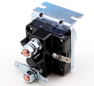
reason, I need nothing from the R1 relay assembly except the Zener Diode / Diode protection circuit as pictured below.

What I want to do is replace the bulky black box with the two components wired in-line. Can anyone help me to identify the correct diodes?
Massive thanks in advance! Apologies if the pic is a touch too wide!
Tim
[Edited on 17/12/12 by TimC]
ChrisW - 18/12/12 at 12:23 AM
I'd need to see a bit more of the diagram in order to help. Others might have more specific knowledge of the application though.
Chris
Madinventions - 18/12/12 at 12:53 AM
When you turn off a relay by removing the voltage across the coil, the collapsing magnetic field inside the coil will generate a very short voltage
spike that can be hundreds of volts. This is normal and almost all coil driven relays will do this.
The two diodes are wired across the coil to clamp this voltage spike to manageable levels and in this appllication I assume that they will be
protecting the contacts of the starter push button. Without these, every time you release the starter button there will be a tiny spark inside the
contacts of the button and given time these will either eat away the contacts or weld them together. The spike voltage may also harm ECUs and other
electronics if not clamped correctly.
I would suggest replacing the bottom part with something like a '1N5408' rectifier diode, and the top part with something like a 18-24V
Zener diode with at least a 3W rating. Note that this allows for about 3A of spike current which may be enough, or it may not depending on the size
of the starter relay. Also the zener voltage is bit of an educated guess and may or may not be the right value for this application!
If you have one of these parts that is functional, you could theoretically apply some voltage across it (with appropriate current limiting) and see at
what voltage it starts to conduct. That would tell you the breakdown voltage of the zener diode.
Hopefully someone will be along with some more suggestions of actual voltages for this unit soon!
Ed.
TimC - 18/12/12 at 09:26 AM
Thanks Ed,
If it helps, the starter relay will be a standard old-school Lucas type.

Thanks again.
Tim
baz-R - 31/12/12 at 03:54 PM
as said the combo of the two diodes is there to prevent the spike of voltage as the coil in the solonoid colapces.
this is fitted in parellel to the coil of the solonoid to prevent spikes enetring the system that might damage sensitive equipment like ecu's and
other eletronics.
i think a simple std diode and 20v zenner should do the job rated around 1A
could you not just use what was fitted to the bike chop it up even just to get what you want from it?
TimC - 31/12/12 at 04:25 PM
Thanks Baz - I've bought the components as previously suggested and am going to give the proposed method a go.
TC


