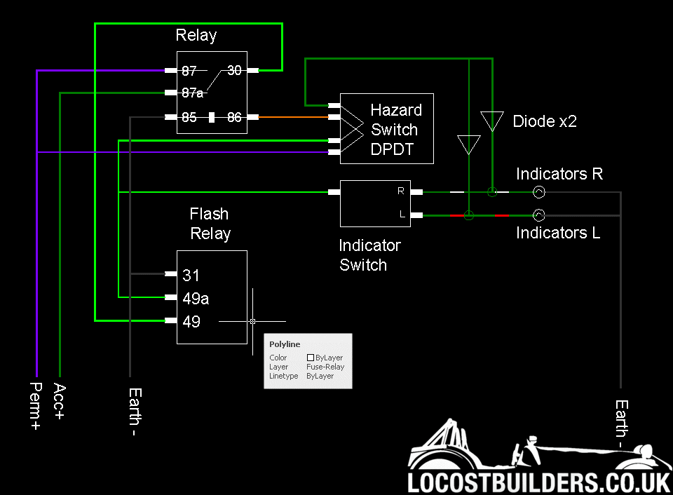
Ive come up with this:

Will it work?
any suggestions/comments?
[Edited on 5-3-13 by loggyboy]

Ive seen a few ideas around recently for hazard wiring. But some seemed to use OE switch gear which can often incoporate functions that a standard on
off doesnt, and, whist I havent decided 100% yet, I may use 'off the self' switches for hazards and indicators, or just the hazard.
Ive come up with this:

Will it work?
any suggestions/comments?
[Edited on 5-3-13 by loggyboy]
Why not buy this kit?
LED Hazard warning system for bike / trike / kit car (MOT) | eBay
I fitted mine in 20 mins
quote:
Originally posted by The Venom Project
Why not buy this kit?
LED Hazard warning system for bike / trike / kit car (MOT) | eBay
I fitted mine in 20 mins
Looks fine to me on first inspection.
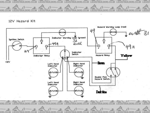
Hi
This is what we did
Works fine
Good luck


hazard wiring
quote:
Originally posted by renetom
Hi
This is what we did
Works fine
Good luck
hazard wiring
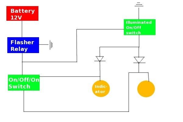
This my setup, simple but works

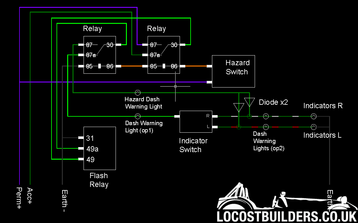
After all my comments about having (what im naming) anticlash, the diagram ive done does still allow the hazards and indicators to work at same time,
and I see no other way to avoid this than to have ANOTHER relay to disconnect the supply to the indicator switch when the hazards are activated.
Unless I can find a DPDT automotive relay which doesnt seem to exist. Anyone know of one?
Just don't then them on at the same time ;-)
In answer to your wquestion though no I don't.
quote:
Originally posted by theduck
Just don't then them on at the same time ;-)
In answer to your wquestion though no I don't.

Hmmm.... This is more difficult than it sounds. Still trying to figure out a way though.
I don't see any problem in using the indicator stalk while the harards are on in your first diagram? The relay will still pulse the same way, so there will not be any difference in moving the stalk when the indicators are on?
quote:
Originally posted by rost
I don't see any problem in using the indicator stalk while the harards are on in your first diagram? The relay will still pulse the same way, so there will not be any difference in moving the stalk when the indicators are on?
the first diagram should work
the second needs amending so the relay coils are in parallel, (currently drawn in series)
however, if you can use a dpdt switch its possible with 2 diodes, and no relays
or dpst switch with 3 diodes, no relays
or spst, 2 flasher units, and 3 diodes, no relays
or dpdt, 2 flasher units, no diodes, no relays
else a suitable dpdt relay would be
http://uk.rs-online.com/web/p/non-latching-relays/7495155/
ps one of the 'clash's you can have, means if the hazards are on, and an indicator, the ignition circuit can be live for ~50% of the time.
quote:
Originally posted by gremlin1234
the first diagram should work
the second needs amending so the relay coils are in parallel, (currently drawn in series)
however, if you can use a dpdt switch its possible with 2 diodes, and no relays
or dpst switch with 3 diodes, no relays
or spst, 2 flasher units, and 3 diodes, no relays
or dpdt, 2 flasher units, no diodes, no relays
else a suitable dpdt relay would be
http://uk.rs-online.com/web/p/non-latching-relays/7495155/
ps one of the 'clash's you can have, means if the hazards are on, and an indicator, the ignition circuit can be live for ~50% of the time.