They are quick garage scribbles mind
 The engine is a GSXR 1000
Could those with a little more experience than me cast an eye on these three circuits for me please and advise if there are any potential issues.
They are quick garage scribbles mind  The engine is a GSXR 1000
the first one appears to allow beam headlights without sidelights, (and rear lights ! )
which I think would fail iva
not sure why you want two relays in the reverse either.
quote:ah, I see its to do 'neutral' interlock, - in that case the in neutral switch just has to be to ground when out of gear, - it doesn't need to go to 12v in gear.
not sure why you want two relays in the reverse either.
The first relay diagram seems to allow main beam to work but as far as i can work out dip will never work as the relay isnt earthed for switching or
connected in such a way that there will be a difference in voltage t activate it. it will allow main beam to be on irrespective of the side lights or
not.
the second ....you dont need two relays to do the reversing motor....the second relay does the job that the first does.......the relay wont activate
until the engine is neutral and the momentary switch is pressed, it then just switches on the second relay which is totally superfluous. The hazard
switch from a ordinary dpdt switch is much easier to wire up and you dont need diodes..
switch 1 2
3 4
5 6
from the terminals......connect 1 to left hand indicator switch output, 2 to right hand indicator switch output.
3 to left indicator bulbs, 4 to right indicator bulbs, join 5 + 6 together and connect to the Hazard relay output.
[Edited on 26/6/14 by snowy2]
quote:
Originally posted by gremlin1234
quote:ah, I see its to do 'neutral' interlock, - in that case the in neutral switch just has to be to ground when out of gear, - it doesn't need to go to 12v in gear.
not sure why you want two relays in the reverse either.
quote:
Originally posted by snowy2
The first relay diagram seems to allow main beam to work but as far as i can work out dip will never work as the relay isnt earthed for switching or connected in such a way that there will be a difference in voltage t activate it. it will allow main beam to be on irrespective of the side lights or not.
the second ....you dont need two relays to do the reversing motor....the second relay does the job that the first does.......the relay wont activate until the engine is neutral and the momentary switch is pressed, it then just switches on the second relay which is totally superfluous. The hazard switch from a ordinary dpdt switch is much easier to wire up and you dont need diodes..
switch 1 2
3 4
5 6
from the terminals......connect 1 to left hand indicator switch output, 2 to right hand indicator switch output.
3 to left indicator bulbs, 4 to right indicator bulbs, join 5 + 6 together and connect to the Hazard relay output.
[Edited on 26/6/14 by snowy2]
When I get home tonight I will post my diagrams which use ordinary toggle switches (or any other).....
quote:
Originally posted by snowy2
When I get home tonight I will post my diagrams which use ordinary toggle switches (or any other).....

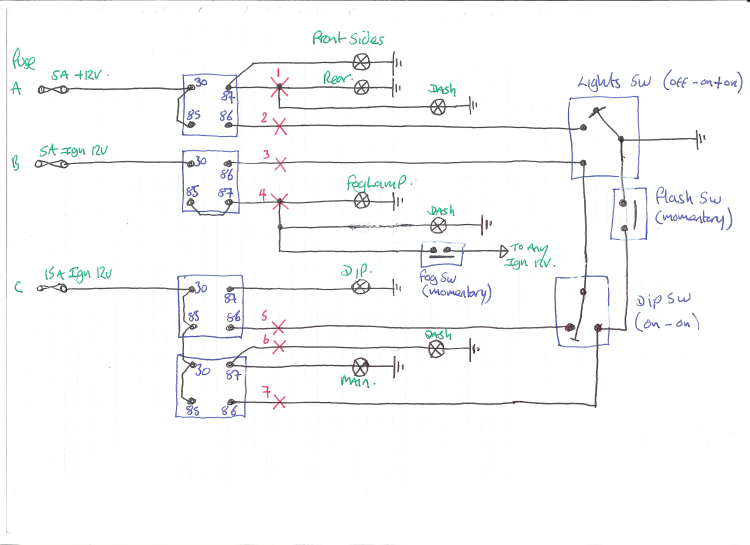
explanation,
the switches can be of any type, i like chrome toggle switches, but standard car switches can be used. the circuit is earth switched ....so the dash
area has almost no current flowing and any short will only activate the circuit.
the fog lights will only come on if the ignition is ON and if the lights are on (not just sides) the fogs are connected via a latching relay and a
momentary switch, they will automatically go off if the lights OR the ignition is turned off (as per IVA requirement)
The red "X's" show where the wires connect under the dash and are for my system of wiring a car. you can ignore them.
light switch needs to be Off, on(1) and on (1+2) the dip switch is just a standard spdt switch with 3 terminals, the flash switch is a momentary
switch.
I don't think this is going to solve mine as I have no off on on switch, savage switches only latch or a dip switch ? I don't want to use
toggles now I've invested in these and cut my dash 
I have the following, all latching savage switches,
Side light switch
dipped switch
main beam switch
fog switch
post the switch pin out and i will see what i can work out.......i assume the switches come with basic wiring and descriptions......
quote:
Originally posted by snowy2
post the switch pin out and i will see what i can work out.......i assume the switches come with basic wiring and descriptions......
This may help with the lighting, bare in mind it's untested. There is no courtesy hi beam flash but as you have separate switches for each
function it's not practical, unless another relay and momentary switch was fitted. Green and black wires can be quite light as they only power
the relay coils.
Description
Some info here, but will assume you have a dip/ main switch on the column
http://www.polevolt.co.uk/acatalog/Side%20and%20Headlights.pdf
quote:
Originally posted by marco
quote:
Originally posted by snowy2
post the switch pin out and i will see what i can work out.......i assume the switches come with basic wiring and descriptions......
Here we go,
I need to use one side of the switch pins for my side light led dim idea, the led's in these are very bright so when i switch the sidelights on I will use a resistor to reduce the +v to the led pin, when sidelights are off it will take the full 12v+ from the switched side positive so in daylight when pushed in the led will be at full and when not in use will be off.
[Edited on 27/6/14 by marco]
quote:
Originally posted by Smoking Frog
This may help with the lighting, bare in mind it's untested. There is no courtesy hi beam flash but as you have separate switches for each function it's not practical, unless another relay and momentary switch was fitted. Green and black wires can be quite light as they only power the relay coils.
Description
quote:
neat.....but.....
your circuit assumes that the dip will stay on when the main beam is activated as the power to the second relay is dependant on the first being powered up once you switch over to main beam the relay powers down and there is no power for the second relay.

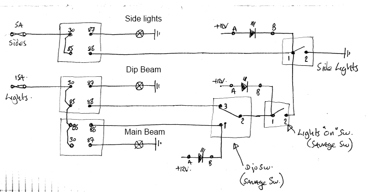
this should work with your savage switches.......the numbers on the switches corresponds to the diagram you gave earlier, the led's need a
separate +12V supply and to be connected as shown. i have not included flash or fogs as i dont know if your savage switches also have a momentary
option.
you should get the leds to illuminate as the switches are operated the main beam/dip sw i assume glows blue when "ON"
But to add a flash switch just connect terminal 1 on the dip switch to terminal 2 on the side lights switch with a momentary switch between, the main
beam should flash.
[Edited on 28/6/14 by snowy2]
quote:
Originally posted by snowy2

this should work with your savage switches.......the numbers on the switches corresponds to the diagram you gave earlier, the led's need a separate +12V supply and to be connected as shown. i have not included flash or fogs as i dont know if your savage switches also have a momentary option.
you should get the leds to illuminate as the switches are operated the main beam/dip sw i assume glows blue when "ON"
 very much appreciated..
 No problems.....glad to help.
one thing.....you could leave the lights "ON" switch on and turn the whole lot off by just switching the sides off....
P.S. the sides need to be battery live, the other lights ideally want to be ignition switched......