Hazard Wiring is there a flaw in this ?
ken555 - 23/2/16 at 11:57 PM

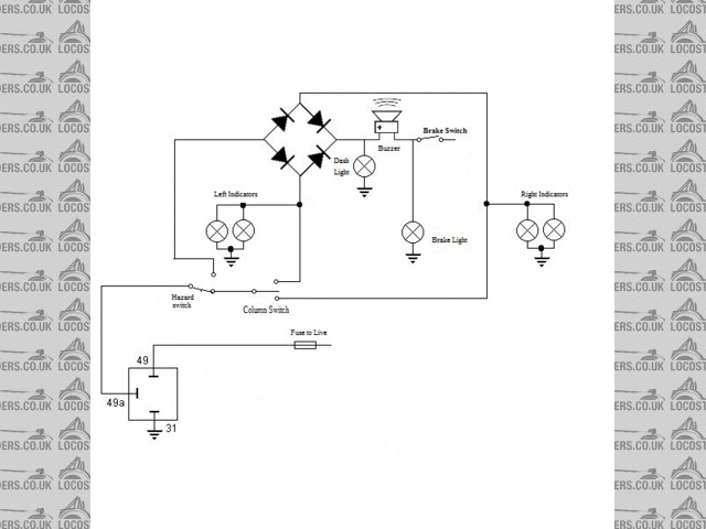
Can anyone see a flaw in this ?
Seems to be the simplest way I can think of keeping the MOT tester happy, and making the wiring simple.
The buzzer grounds thru the brake lights, so when sitting at a junction, you can put your foot on the brake and the buzzer gets 12V at each side and
so is quiet, then when you start moving again, it beeps to remind you to cancel the indicators, the dash light is there as a secondary reminder.
I could use a bridge rectifier in the middle rather than 4 diodes, it needs to power 2x 21w bulbs at the rear, and 2 x 5W bulbs at the front, and one
dash bulb/buzzer. so say 60W total, thats 5 Amps, so a KBPC601 should do the trick.
[Edited on 23-2-16 by ken555]
[Edited on 23-2-16 by ken555]
SteveWalker - 24/2/16 at 12:35 AM
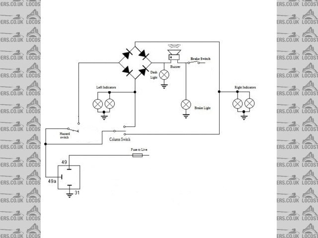
How about using a 2-pole changeover switch for the hazards? One pole can switch the power supply to the bottom relay between the switched and
permanent 12V, while the other can switch pin 49a of the same relay between the column switch and the bridge rectifier. No need for the top relay
then.
Don't you need a specific hazard warning light on the dash though? If so, a lamp between the input to the bridge rectifier and 0V would do.
ken555 - 24/2/16 at 01:08 AM
quote:
Originally posted by SteveWalker
How about using a 2-pole changeover switch for the hazards?
Don't you need a specific hazard warning light on the dash though? If so, a lamp between the input to the bridge rectifier and 0V would do.
Like this ?

Using this switch that matches the rest.
Mot tester
manual, 1.4 - page 2 says quote:
The hazard warning lamp "tell-tale" maybe a separate light or the same as the indicator "tell-tale". However , it must be a
flashing light.
So looks like I've covered that base.
[Edited on 24-2-16 by ken555]
[Edited on 24-2-16 by ken555]
TheGecko - 24/2/16 at 02:58 AM
Tell me if I'm misreading what you're doing but, if the buzzer is finding ground through the brake lights, they're going to flash in
time with the indicators while your foot is off the brake.
Dominic
[Edited on 24/2/2016 by TheGecko]
ReMan - 24/2/16 at 07:57 AM
quote:
Originally posted by TheGecko
Tell me if I'm misreading what you're doing but, if the buzzer is finding ground through the brake lights, they're going to flash in
time with the indicators while your foot is off the brake.
Dominic
[Edited on 24/2/2016 by TheGecko]
This is my one concern the rest is fine either way
Will depend on the spec of the buzzer I expect but it doesn't look good practice?
ken555 - 24/2/16 at 09:37 AM
quote:
Originally posted by TheGecko
Tell me if I'm misreading what you're doing but, if the buzzer is finding ground through the brake lights, they're going to flash in
time with the indicators while your foot is off the brake.
Dominic
[Edited on 24/2/2016 by TheGecko]
The current through the buzzer is so low, nothing happens in real life.
I have that currently working, its just the hazards that's the new(ish) bits.
My road car (a Toyota yaris) has the tell-tell wired across both sets of indicators, so it earths through the unused indicator circuit, same
principle.
z2000 - 24/2/16 at 12:04 PM
If I understand the diagram correctly as it stands, I *think* that pressing the brake would send power through the buzzer AND through the dash light
(in series) so you'd get a low sounding buzz and a dim dash light.
Nothing would flash because of the right hand pair of diodes preventing and current travelling to the left side of the circuit?
All of this would be in parallel to your brake light so you shouldn't see too much of an effect in it's brightness?
Edit: Also to add on the other part of the discussion, using the indicators or hazards will send power through the buzzer AND brake lights (in series)
so your buzzer will not sound as loud and your brake lights will come on dimly?
Or I could be talking rubbish....
Perhaps just earth the buzzer somewhere else?
Henry
[Edited on 24/2/2016 by z2000]
[Edited on 24/2/2016 by z2000]
snowy2 - 24/2/16 at 07:03 PM
Bit puzzled about a bridge rectifier in a dc circuit....there are much better ways of achieving the same goal....
ReMan - 24/2/16 at 07:07 PM
Nothing wrong with the B R its just 4 diodes serving a logic purpose
ken555 - 24/2/16 at 07:23 PM
quote:
Originally posted by ReMan
Nothing wrong with the B R its just 4 diodes serving a logic purpose
One unit instead of four, plus it comes with a handy mounting hole in it.
Oh and I can get them free.
gremlin1234 - 24/2/16 at 09:41 PM
the first diagram does have one significant flaw,
if you have the hazards on, and leave an indicator on, with the ignition off, everything that is powered from the 'switched live' will be on
in time with the flashers.
a simple solution to this is using just one flasher relay, powered from the permanent live; or to add another diode in the switched feed.
edit


hazard
another edit, slightly simpler


hazard
[Edited on 24/2/16 by gremlin1234]
02GF74 - 24/2/16 at 11:16 PM
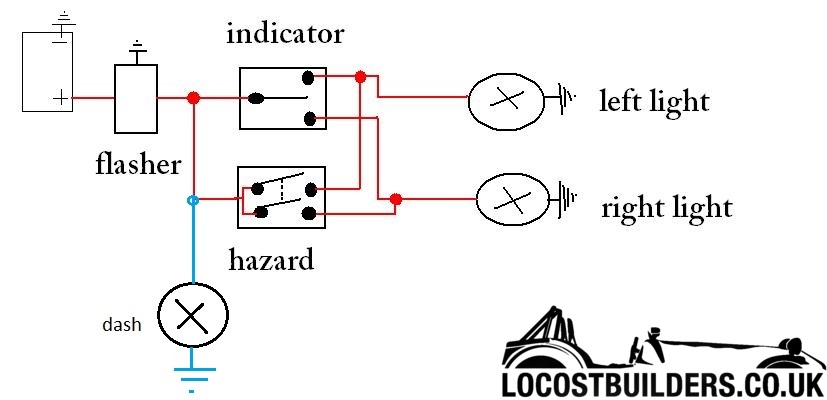
ok, I've not given this as much tough as you have, but why not use a conventional circuit with dpdt hazard, example pulled from web e.g.
fit the buzzer across the dash lamp.

gremlin1234 - 25/2/16 at 01:03 AM
quote:
Originally posted by 02GF74
ok, I've not given this as much tough as you have, but why not use a conventional circuit with dpdt hazard, example pulled from web e.g.
fit the buzzer across the dash lamp.

won't the dash lamp be on all the time apart from when its flashing?
02GF74 - 25/2/16 at 02:11 PM
Dont think so. Flasher unit has bimetallic strip that is heated when circuit is completed. It makes contact when cold so lights are on. Once
heated, the strip bends so no conract, lights go off and strip cools .... until contact is made again and the cycle repeats.
Downside is indicators would flash when ignition is off, remedied by a relay from ignition switch.
gremlin1234 - 25/2/16 at 05:05 PM
quote:
Originally posted by 02GF74
Dont think so. Flasher unit has bimetallic strip that is heated when circuit is completed. It makes contact when cold so lights are on. Once
heated, the strip bends so no contact, lights go off and strip cools .... until contact is made again and the cycle repeats.
Downside is indicators would flash when ignition is off, remedied by a relay from ignition switch.
when the strip is cold, it conducts, so the dash light would be on all the time, until it is heated enough by the indicators in use, when it
would flash. - this could be solved by putting the dash lamp between the feed and output of the flasher unit, but would make adding a buzzer (that is
silenced by the brake lights) difficult.
I don't see indicators working without the ignition on as a problem.
there is one other problem, that they will flash faster as hazards than just one indicator. - again not to much of a problem, - or an electronic
flasher could be used.
edit:
after re-reading the thread...the post on 24/2/16 at 01:08 AM by ken555 (the op,) should just work too.
[Edited on 25/2/16 by gremlin1234]
02GF74 - 25/2/16 at 06:09 PM
Yes. Sorry. My bad. Good job someone is paying attention.

In fact i remember having this on my land rover, solution is either have two dash lamps, one for each side as on my kit car else use diodes as i did
on my landrover, think it was similar to the BR as posted earlier.


