Another Denso Alternator question
40inches - 30/3/16 at 01:58 PM
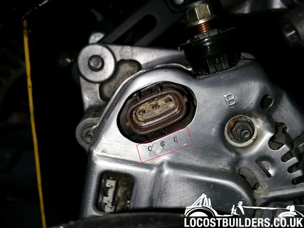
Got round to wiring the alternator, and found it has different connections to the other Denso Alternators 
Am I right in thinking that I have an ECU controlled Alternator, that C is the ECU control connection, G is ignition and L is dash lamp?
Also if I don't connect the C connection the output will default to 13.5 volts? As it did on the wife's Focus after the ECU wire came
adrift.

tims31 - 30/3/16 at 02:44 PM
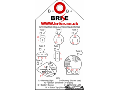
Does this help


Description
SJ - 31/3/16 at 07:59 AM
That looks like mine. It is diagram 4 in Tims31 post. It isn't ecu controlled. Mine is from a Kubota digger. From memory I think the connections
are permanent live, switched live and warning light.
The light output is just a signal though and won't light a bulb. I used mine to switch a diode that controls the LED on my Acewell dash.
ChrisL - 13/5/16 at 03:40 PM
I thought it is: Lamp; Ignition switched live and an Output for the ECU (to see what the alternator is doing as opposed to controlling it)
40inches - 13/5/16 at 04:32 PM
quote:
Originally posted by ChrisL
I thought it is: Lamp; Ignition switched live and an Output for the ECU (to see what the alternator is doing as opposed to controlling it)
My thoughts exactly, I have left the ECU output wire off, will see when I start her up 
britishtrident - 13/5/16 at 05:15 PM
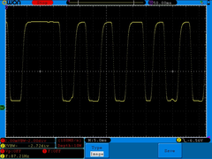
It is the signal from the alternator to the ECU to enable the ECU to adjust the idle speed to prevent stalling.
The output is the a square wave the duty cycle of which varies with load, normally about 40 pecent duty cycle at idle with no load, 0 percent at full
electrical load.
Here is a capture I grabbed from a 105 Amp Denso at idle


Denso Alt Duty Cycle Idle


