Handbrake and Horn
Benzine - 6/8/05 at 08:56 AM
After a search I couldn't find anything specific. I have a PWS loom and a digidash and I can't get the horn or handbrake to work
The handbrake has a brown/yellow wire running to it which I've put the right connector and and fitted to the handbrake. I've also earth the
handbrake here too. At the end where the wires meet the dash I have a black wire and 2 x brown/yellow. Using a test light, the black has power but the
brown/yellows do not (with handbrake on and off) Just wondered how people wired this up?
And the horn. I have 2 wires in the front loom - red/yellow and red/green. Test light shows red/yellow has power. I can trace this wire to the dash
area but not the red/green. I'm not using a stalk so am I right in that I need to use the red/green wire? Above the steering wheel I have 2 brown
wires in a plug and at the horn I have 2 terminals. I've tested the horn but it always stays on. How have others wired this?
Thanks a million
JoelP - 6/8/05 at 09:35 AM
handbrake:
brown yellow is to earth the dash light on, as you say it earths at the handbrake end. The black (if its anything like the sierra system) will be a
live, from a fuse to the dash light. Does your master cylinder reservoir have 3 wires or two? This would influence how it is wired. If it has 3, two
should be linked - do you have a continuity meter? If you can identify the linked ones, the live from the dash light will come to one of these, the
linked on then goes to the handbrake, the other is the switched side from the reservoir float, and should just be earthed anywhere.  If your
reservoir has a test button on it, you dont need the handbrake side of things at all. You could then just wire up an alternate handbrake warning light
if you wanted
JoelP - 6/8/05 at 09:39 AM
with the horn, do you know if there is provision for a relay? this is, IMHO, required, but maybe not everyone would agree. I suppose a 30A switch
would be ok by itself. I would wire it with a thin wire feeding the switch, then a wire from the other side to the relay. Earth the opposite side of
the relay. The take a live feed on a thick wire to the 3rd point of the relay, then from the 4th the the horn and then to earth. This is just one
alternative way of doing it, you could choose to have the switch in the earth side of the relay. Also, you obviously need to make sure you get the
points of the relay wired up correctly!
Benzine - 6/8/05 at 11:53 AM
Hmm, I don't understand how the master cylinder works with the handbrake :S So it's used to test the amount of brake fluid left?
I have a 3 pin connector on mine with a yellow push button by the way
Peteff - 6/8/05 at 02:01 PM
The power goes into your warning light and earths through either your handbrake when it is applied or your fluid sensor when it is activated or your
test button on top of the cylinder when it is pressed, bn, bn/y or bn/gn on the Sierra. The handbrake and the button only test whether the light still
works. If the fluid runs out it earths through the brown wire.
Benzine - 9/8/05 at 09:11 PM
I still don't get it 
I have discovered various things using a test light kit:
The black wire here has power. One of the brown/yellow ones has a strong earth when the handbrake is applied. Nothing happens with the other
brown/yellow and I don't know how these 3 wires connect to the M/C in any way. (these 3 wires are part of the PWS loom which goes to the
instruments)

M/C with test button. 3 terminals, I'm told to use the end 2 but how? I've tried connecting to the wires at the other end but nothing
happened.

Benzine - 9/8/05 at 09:14 PM
Oh and I also don't get the horn at all 
The horn. 2 terminals. Should one be earthed?

The steering wheel end of things. 2 terminals

The horn end of things. 2 wires. The yellow/red is getting power, the green/red is not. According to the PWS manual for a horn operated from the wheel
(and not a stalk) I should use the green/red

[/n00b]
JoelP - 9/8/05 at 09:29 PM
ok, one simple step for each!
the m/c, use the test meter to identify which two terminals are linked, on the reservior cap 
the horn, is the yellow/red wire perminantly live, or is it only live when you depress the switch. This will tell you which side of the circuit is
switched!
Good luck! 
Benzine - 9/8/05 at 09:55 PM
quote:
Originally posted by JoelP
the horn, is the yellow/red wire perminantly live, or is it only live when you depress the switch.
It's always live 
G.Man - 9/8/05 at 10:01 PM
Doesnt the horn press earth the horn...
So the both go to horn and when you depress switch the horn makes a full circuit and blows...
Handbrake should do similar or are you talking about brake fluid resorvoir level?
??
Benzine - 9/8/05 at 10:05 PM
quote:
Originally posted by G.Man
Doesnt the horn press earth the horn...
So the both go to horn and when you depress switch the horn makes a full circuit and blows...
Handbrake should do similar or are you talking about brake fluid resorvoir level?
For the handbrake I'm talking about using the handbrake as a tester for the M/C (i think so anyway  )
)
As for the horn, in the loom around the scuttle I can't find the green/red wire to go to the brown switch, only the red/yellow
Benzine - 10/8/05 at 09:05 AM
Honk honk! Horn works now. It was green/red that was live. I put that to one horn terminal, the red/yellow to the other horn terminal, the red/yellow
to the brown terminal on the column and earthed the other terminal at the column. 
Now for the handbrake 
[Edited on 10/8/05 by Benzine]
JoelP - 10/8/05 at 07:33 PM
did you find the linked terminals on the chamber? i think they would all be linked if its not floating!  so hold the float up
Benzine - 11/8/05 at 01:53 PM
Here's the potision I'm at now...
Edit: Diagram should read '3 wires from PWS'

With the wiring this way, if I press the test button on the M/C or tilt it upside down (it's out of the res at the moment for testing) then the
light on the dash goes off 
From wire number '6' i'm getting an earth signal on the test light when the handbrake is applied. Not sure how this ties in the the
M/C. I tried putting it to terminal 3 but that made things sizzle 
Terminal 2 and 3 seem similar, with the test light, when I pressed the button I get power from terminal 1. Not sure what to test for on each terminal,
earth or live?
Any ideas?  Spanks
[Edited on 11/8/05 by Benzine]
James - 11/8/05 at 02:08 PM
Benzine,
I'm sure there's something wrong there as I'm sure that the instructions from Premier say to use the M/C outer connections- ie. 1 &
3 in your pictures.
These are what I've used and everything works fine on mine!
When I look at my connector plug I can see that 1&2 are linked together anyway!
As for the handbrake... it's one wire feed to it and it earths through the chassis.
Not much more to it than that as far as I can tell! 
HTH,
James
[Edited on 11/8/05 by James]
Benzine - 11/8/05 at 03:50 PM
Okay now I'm using 1&3 and the test button still works. I just can't work out how the handbrake fits in to all this :S At the moment
when the handbrake is turned on I get a good earth from the wire to it, but where does this wire go? :S

JoelP - 11/8/05 at 09:33 PM
have to edit this in bits cos i keep forgetting stuff!
6 is obviously the handbrake earth, this needs to go to the m/c too. number 2.
then live to the light, and from the light to number 3.
number 1 gets a direct earth.
This setup would also only use 1 and 3 if the handbrake wasnt being used as the test switch.  Makes it similar to what james said
[Edited on 11/8/05 by JoelP]
do really try this, im fairly sure it will work 
[Edited on 11/8/05 by JoelP]
Benzine - 11/8/05 at 09:47 PM
Awesome, thanks. Will try at sparrows fart.
Benzine - 12/8/05 at 10:03 AM
I just tried it all 
quote:
Originally posted by JoelP
then live to the light
This means that the light is always on. I've just spoken to the digidash people. The handbrake needs to act as a switch for the 12V live wire. So
I was thinking if I split this wire between the M/C and the handbrake both will work. However how do I rig up the 12V wire to the handbrake? Because
the handbrake it earthed, whenever I put a live wire to it, it just sparks :S
Waaahhhhh 

JoelP - 12/8/05 at 07:47 PM
you are right, the handbrake is a one wire switch, the other goes straight to earth.  To have it switching a live you would need two wires to it.
Maybe they dont intend you to use the standard switch?
If putting the live to the light makes it light up, then something must be earthed. Either the fluid sensor, or the handbrake, or a wrong wire.  I
wish i was close enough to come down and help
Benzine - 12/8/05 at 09:40 PM
What I've done is got a red light for the dash and wired it up. Worked straight away so that works for the handbrake, will this be okay for SVA?
So i have the brake warning light on the digidash and the red separate light for handbrake. Maybe I need to mark that's what it is
JoelP - 12/8/05 at 10:29 PM
you dont need a handbrake light at all, so it might be easier just to remove the bulb  provided the test switch works on the m/c.
Benzine - 12/8/05 at 10:40 PM
 Haha. If only I'd read into that first
  Yeah the M/C switch works a treat.
Peteff - 12/8/05 at 11:15 PM
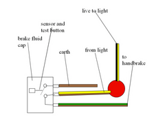
The handbrake earths the light, there should be power to the bulb and you should be able to test the bulb from the drivers' seat which is why the
handbrake is used as a test as well as a warning light. In the car the cap is wired like this.


Rescued attachment brakecap.jpg
Benzine - 13/8/05 at 07:39 AM
So SVA I have to be able to test the M/C from where I sit in the car?
The thing with the dash I don't understand, if the live wire goes straight to the bulb the light will go on. There's one wire leading
to the brake test light and I need that to be a switched live but I don't see how to do this if the handbrake switch is earthed :S:S
JoelP - 13/8/05 at 08:13 AM
you can have the switch in the earth side or the live side, it makes no difference! Petes diagram is excellent, and it is indeed showing earth
switching.
Benzine - 13/8/05 at 08:59 AM
Just wanna clear something up. The digidash has it's own earth supply. If the live wire is taken straight to the bulb it will always light up
regardless of anything else. If I were able to switch the live wire then I could get it all working. I can't use the handbrake to control the
live wire as it's earthed and just causes sparks. Can I use a small switch in someway to test the M/C from the drivers seat? As that
wouldn't be earthed, I can run a live to it.
I don't know what I'm doing wrong. Surely someone must have used a digidash before, I'd just like to know how they've wired up the
handbrake.
R.I.P another fuse (I now have a pile of about 20 dead ones  )
)
[Edited on 13/8/05 by Benzine]
JoelP - 13/8/05 at 01:04 PM
Sorry, i didnt know the digidash had its own earth  that sort of stuffs up the switched earth plan!
So you need switches in the live side of it all.  Assuming its not LED lights, you could probably just reverse everything in petes diagram.
Benzine - 13/8/05 at 01:46 PM
quote:
Originally posted by JoelP
Assuming its not LED lights
They're LEDs 
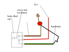
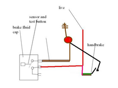
Is the test switch used purely to test the bulb in the dash? If so I can wire a switch in which would be simple. Thus:

The switch would work in the same way as the switch at the M/C and the blub would light. It could be dash mounted and used to test the bulb. Is that
okay? 
[Edited on 13/8/05 by Benzine]
JoelP - 13/8/05 at 01:58 PM
cant seem to post a picture... gimme 2 mins to try! 
but yep, you're correct. 
[Edited on 13/8/05 by JoelP]
JoelP - 13/8/05 at 02:00 PM
try again...


Rescued attachment untitled1.JPG
JoelP - 13/8/05 at 02:01 PM
or this, same really.


Rescued attachment untitled1.JPG
Benzine - 13/8/05 at 03:41 PM
Thanks for the diagrams...blew another fuse though 
My button switch is wired up and when pressed, the dash light comes on. Is this okay or is it the actual M/C plug circuit that needs to be tested? If
it's just the bulb in the dash then I can put this to rest 
JoelP - 13/8/05 at 05:02 PM
i think its just the bulb you need to test, but after my previous wrong advice it might be best to wait for confirmation! 
 If your
reservoir has a test button on it, you dont need the handbrake side of things at all. You could then just wire up an alternate handbrake warning light
if you wanted


 )
) 


