brake test switch
kev R1 - 13/2/06 at 10:03 PM
on my indy i have a ford brake cylinder with the yellow plunger on the top.out of the side there are three wires coming out from a plug,
1 x brown
1x brown/yellow
1x brown/ green
can someone please help me out as how to wire this into my durite brake test switch,cheers kev
flak monkey - 13/2/06 at 10:10 PM
Brown is earth
The other 2 are switched earths:
Brown/yellow goes to the warning light (the other side of the light needs a permanent (switched when the ignition is on) live feed to it)
Brown/green to the handbrake switch (or in your case to the test switch, connect the other side of the switch to earth (-ve))
I assume your switch has the warning light built in? If so, combine the above. So switch contacts - one brown/green, other to earth. Then light
contacts one to brown/yellow and the other to a live feed.
When the fluid level drops it connects the brown to the brown/yellow and brown/green (they are connected inside the switch anyway), thus completeing
the circuit and lighting the warning light.
Hope that all makes sense,
David 
[Edited on 13/2/06 by flak monkey]
Deckman001 - 13/2/06 at 10:29 PM
 What a dam fine explanation !!


Jason
kev R1 - 13/2/06 at 10:33 PM
that's great thankyou very much!!!!
flak monkey - 13/2/06 at 11:31 PM
quote:
Originally posted by Deckman001
 What a dam fine explanation !!


Jason
Why thank you 
Having spent the past week playing around with that loom, I would hope that the explaination's correct!
One question though...where did you get your switch from? Might be just what I am looking for...
There is no requirement for the switch to be marked is there? As long as the light it 'tests' has the right symbol? If so, my life is a lot
easier, and I have less wires to move in my loom.
Cheers,
David
iank - 14/2/06 at 08:38 AM
Modern cars don't have a brake test switch on the dash, they use one on the handbrake to make testing automatic, so I can't believe it
needs to be marked. Having said that both the savage switch and mini test switch both have the lit symbol as part of the switch.
As always the men with clipboards might have a different opinion 
Rubix - 14/2/06 at 01:21 PM
David,
Mines not marked up and the SVA fella never blinked. so quite sure there is no requirement for the push button to be marked up, just the light on the
dash. 
flak monkey - 14/2/06 at 01:26 PM
Cheers 
That means I can just wire in my Bright6 and have a push-to-make switch on the dash (since thats where the test wires are anyway!)
David 
kev R1 - 23/2/06 at 09:33 PM
right got the switch to light up when pressed but can't seem to make it light up when the plunger is pressed and is this tested for sva? kev
flak monkey - 23/2/06 at 09:38 PM
Yes its tested, because thats what it must do...
The colours I gave you are the ones which fit with the sierra manual, but the manual could be wrong.
What colour wires have you got running to your level switch that fits on the resevoir?
When the float in the switch is at its lowest position, ie if the resevoir was to be empty, it should light the switch, when depressed (as if the
level was high) the light should remain off.
David
kev R1 - 24/2/06 at 05:45 PM
brown
brown/yellow
brown/green
using a durite switch,
flak monkey - 24/2/06 at 05:54 PM
When the float is high, as if there was fluid in the resevoir then the brown/yellow and brown/green should be connected. There should be no connection
between either and the brown wire.
When the float is low, as if there was no fluid in the resevior all 3 wires should be connected.
Verify those with a multimeter.
The brown/yellow is the switched earth which should go to the light in the switch.
The brown/green should go to the test switch. The other side of the switch needs connecting to ground.
The brown from the m/c should be connected to ground.
You need a live feed to the other side of the light as well, which is black/yellow in the original sierra.
If that doesnt work, I dont know what to suggest at the moment!
David
[Edited on 24/2/06 by flak monkey]
flak monkey - 24/2/06 at 06:06 PM
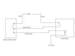
This wiring diagram helpful? I just drew it quickly on paint, so its a bit crummy! Sorry!
It shows the mastercylinder as if the fluid level is correct. When low, the switch would be closed.
David
[Edited on 24/2/06 by flak monkey]


Rescued attachment mc wiring.JPG


 What a dam fine explanation !!

