Relays for Premier Wiring Loom (Mk2)
Dick Axtell - 11/8/08 at 01:48 PM
Right - here is some background info from a previous thread.
http://www.locostbuilders.co.uk/viewthread.php?tid=45001
I have some relays, but I'm uncertain of their use, i.e which one goes where? The thread referred to above, mentions a "tall red"
relay, apparently used for the intermittent wipe. How does one ID flasher, main beam, and headlights relays?
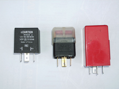
Just for ref, here's a pic of my relays :


Rescued attachment Relays_02.JPG
Dick Axtell - 11/8/08 at 01:49 PM
Clearly, I'm having BIG trouble uploading this particular image. Will try another route.
Well - I'll go t' foot o' b****y stairs!! Where the **** did that come from? Wasn't there just after I uploaded it!!!
Back to the plot :-
Is the lefthand one for flashers? It has only 3 connection tabs, whereas the middle and big red one on the right both have 4 connections. I reckon the
middle one is for either main beam, or headlights, because the pin numbers match the PWS diagram.
Can the red relay be used for any other function?
As usual, your expert advice will be very welcome (if only to stop my temper fraying!!!!)
[Edited on 11/8/08 by Dick Axtell]
[Edited on 11/8/08 by Dick Axtell]
Paul TigerB6 - 11/8/08 at 01:55 PM
The one on the left should be the flasher unit for the indicators / hazards. There will probably also be a 4 blade relay on the indicator circuit.
For the headlight circuit. You will probably have a 5 blade changeover relay with dips and main beam being on pin 87a and 87 respectively. The relays
often have a diagram printed on them as per here so hope this
helps
Editted as i was getting myself confused - 3 pin relay on the left gives the flashes required for your indicators / hazards
[Edited on 11/8/08 by Paul TigerB6]
02GF74 - 11/8/08 at 01:56 PM
the left hand most one is flahser relay.
49 = 12 V supply
31 = 0 V (earth)
49a = to indicator switch
Dick Axtell - 11/8/08 at 02:02 PM
Guys - many thanks for the info.
Any thoughts about using the red one?
Paul TigerB6 - 11/8/08 at 02:15 PM
quote:
Originally posted by Dick Axtell
Guys - many thanks for the info.
Any thoughts about using the red one?
Just editted my first post. Is there a diagram on the red relay at all?? I'd have a guess its the wiper relay
