Huttojb
|
| posted on 6/12/15 at 01:05 PM |

|
|
Corsa C indicators.
Hey all,
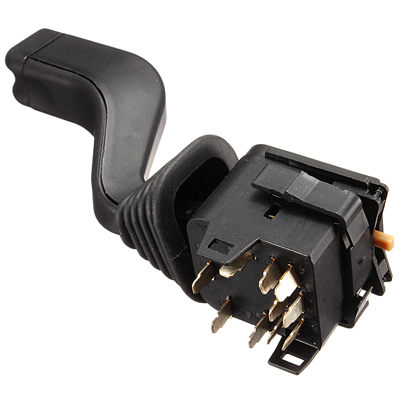
I'm looking to use the Corsa C indicator stalk on my Tiger, the indicator stalk has 4 pinouts, I would imagine +, -, CANH and CANL.
Does anyone have any data onthe pinouts and stalks in general. Any help would be good
Jason
|
|
|
|
|
Rosco86
|
| posted on 6/12/15 at 01:27 PM |
|
|
Bit of a cheeky plug
http://www.locostbuilders.co.uk/viewthread.php?tid=200750
My Build Thread
|
|
|
Huttojb
|
| posted on 6/12/15 at 01:49 PM |
|
|
Rosco86.
Just alittle but, considering it's not even the manufacture I'm looking for. If you can photo a Corsa C stalk installed I could probably
work out pinouts, I would imagine 2 wires are twisted pair (this would be CAN).
Jason.
|
|
|
loggyboy
|
| posted on 6/12/15 at 01:55 PM |
|
|
An reason for using the canbus stalks over the identical looking early versions?
Mistral Motorsport
|
|
|
Huttojb
|
| posted on 6/12/15 at 02:11 PM |
|
|
Loggyboy
Yes, I'm current creating a CANbus for my Car so using the Corsa I'll just tap into the current CAN Signals. Also I don't want the
indicator arm to latch as I have an EPS Which I monitor the steering angle so I can stop the indicators when a pass a window in steering angle.
I didn't relise initially the Stalks where CAN but this maybe a benifit. I wanted them dur to the shape of the arm and the non-latching.
Jason.
|
|
|
loggyboy
|
| posted on 6/12/15 at 11:09 PM |
|
|
Iirc corsa c are latching? They were identical to corsa b in look but had a lot less connector pins.
Mistral Motorsport
|
|
|
Huttojb
|
| posted on 7/12/15 at 07:38 AM |
|
|
Sorry,
I must be talking about the Corsa D then. My girlfriend had one before she had her Fiat 500.
|
|
|
loggyboy
|
| posted on 7/12/15 at 09:39 AM |
|
|
Sorry cant help with wiring pinouts but:
Corsa B (and most 90s vauxhalls)
Corsa C (canbus)

Corsa D

Mistral Motorsport
|
|
|
Huttojb
|
| posted on 7/12/15 at 04:33 PM |
|
|
Thanks loggyboy
This confirms I'm looking for Corsa C then. I'm pretty sure Corsa C don't latch.
Can someone eithet send a picture installed to see the wiring look or measure across the pins. Really need to know the signals.
Thanks.
|
|
|
DW100
|
| posted on 7/12/15 at 04:55 PM |
|
|
Sorry to disappoint you but they are not CAN BUS.
They provide a variable resistance (by switching in different resistors) depending on arm position which the multifunction unit sees a variable
voltage.
So you'll get something like No indicators 0V, left indicators 2V, right indicator 4V. (can't remember actual figures)
Same for light switch.
Pin 3 is common
Pin 1 is lights
Pin 2 is indicators.
|
|
|
Huttojb
|
| posted on 7/12/15 at 07:40 PM |
|
|
DW100
Thanks for the info, that's fine either way I can work this. I'll just out it through a comparitor and logic gates to switch desire
lights.
How sure are you on this info? Is pin 4 12v? I would imagine it's PWMing the signal so it averages out to voltages that is seen on the DMM.
JASON.
|
|
|
DW100
|
| posted on 7/12/15 at 08:40 PM |
|
|
Here Is an Internal diagram of the switch
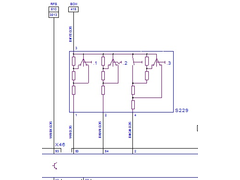 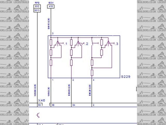
Description
S229.1 Switch - High beam
S229.2 Switch - Turn signal
S229.3 Switch - Cruise control
Nothing clever it is just a voltage divider circuit. No active components inside.
[Edited on 7/12/15 by DW100]
|
|
|
Huttojb
|
| posted on 7/12/15 at 09:12 PM |
|
|
DW100
Brilliant. Your a star!!
This is perfect, been trying to find this info for ages.
It looks like you know this product quite well, you in the automotive industry.
Jason.
|
|
|
spegru
|
| posted on 19/2/21 at 10:55 AM |
|
|
Reviving an old thread.
I'm interested in following up on this due to the now almost universal use of non traditional switches in recent cars
I'm using this youtube channel as an inspiration https://www.youtube.com/watch?v=KcafYreXpqc&t=1516s - esp starting at 18:10
To summarise my understanding so far, the stalk functions are triggered by inserting different resistor values into a circuit and using those values
to instruct a microcontroller to operate traditional relays. This has the advantage of enabling the use of recent switches and also the repurposing of
switch functions for other uses without needing to rewire the stalk itself.
The microcontrollers ATTiny80 and other devices are seriously cheap, almost down to the pence level and it's important to emphasise that
although these switches normally operate via canbus they do no necessarily need to as, as with the merc set in the video, the canbus chip is not in
the stalk itself
Yesterday I spent some time with a Corsa C indicator switch and discovered the following (using that previous diagram in this thread as a
reference)
Pin 3 (brown/yellow) - common feed
Pin 2 (black/white) - Indicator functions
Pin 1 (white) - dip & flash functions
My resistance measurements were:
Pin 3 (brown/yellow) to Pin 2 (black/white)
Indicator functions
Centre = 1.45 kOhm
Left = 0.48 kOhm
Right = 0.15 kOhm
This connection did not react at all to beam/flash funtions
Pin 3 (brown/yellow) to Pin 1 (white)
Beam functions
Neutral position = 1.48 kOhm
Flash position = 0.49 kOhm
Dip position (this does not latch btw) = 0.15 kOhm
This connection does not react to indicator functions
(Incidentally I had some trouble with another multimeter providing very unstable readings so YMMV)
These resistance values are very low so I think need a circuit that puts a resistor and a voltage stabiliser in series with the common feed
(brown/yellow) and (presumably) use the micro controller to detect different voltages from the wires concerned, provide outputs (via driver chips) to
actual physical relays that do the real switching.
Those relays can be anywhere convenient in the car and presumambly the wipers switch works in a very similar way and many other Vauxhall switches of
the same era behave similarly. Via programming they an be used to do any function desired but without necessarily using Canbus.
So Now I need a bit of circuit boffinry. Luckily I am already part way there with microcontroller programming via previous arduino expereince
[Edited on 19/2/21 by spegru]
[Edited on 19/2/21 by spegru]
[Edited on 19/2/21 by spegru]
[Edited on 19/2/21 by spegru]
|
|
|
SteveWalker
|
| posted on 19/2/21 at 11:42 AM |
|
|
If it is intended that they work with external resistances as voltage dividers, then they seem to be ridiculously low resistances.
I'd expect the external resistances to be within an order of magnitude of the internal ones and even if those resistors were 10 x as high,
that's an unusually large current for a simple signal. For instance 10R (plus the 0R15) and 3.3V gives over 300mA! Increasing the 10R to 1K or
so drops the current, but the output voltages from the divider all get closer and closer together and more prone to be affected by noise.
Are you sure that your multimeter is using the right range?
|
|
|
spegru
|
| posted on 19/2/21 at 02:37 PM |
|
|
Ahh yes better make those kOhms.
I'll go back up and edit rather than reposting
[Edited on 19/2/21 by spegru]
|
|
|
SteveWalker
|
| posted on 19/2/21 at 08:04 PM |
|
|
Ah, that sounds much more like it!
|
|
|
spegru
|
| posted on 17/10/23 at 11:20 AM |
|
|
Just reviving this thread again as I'm about to put these switches into action
Resistance figures (rounded)
Indicator switch
Brown/Yellow wire is common
Black white wire is for indicator functions
White wire is for dip & flash functions
Indicator functions: Brown/yellow to black/white
Neutral/off position: 1500 Ohms
Left position 150 Ohms
Right position 477 Ohms
(no reaction to dip/flash functions)
Dip & Flash functions: Brown/yellow to white
Neutral position: 1500 Ohms
Flash: 494 Ohms
Dip: 152 Ohms (does not latch)
Wiper Switch:
Brown/Yellow wire is common
Black/Blue wire is for rear wiper functions
Black/Grey wire is for front wiper functions
Rear wiper & Squirt functions: Brown/yellow to black/grey
Neutral/off position 1200 Ohms
rear wiper on: 198 Ohms
Rear Squirter: 82 Ohms
Front Squirter:436 Ohms
Does not react to front wiper functions
Front wiper Functions: Brown/yellow to black/blue
Neutral/off position: 1240 Ohms
Single wipe: 80 Ohms
Intermittent wipe: 80 Ohms
Slow wipe: 200 Ohms
Fast wipe: 436 Ohms
Does not react to squirt
Does not react to rear wipe functions
Check out Invader Garage on Youtube
https://www.youtube.com/channel/UC3C55qk-tbKc0WjmxGqFoXg
|
|
|
spegru
|
| posted on 23/11/23 at 01:07 PM |
|
|
And here is my prototype fully working Corsa Column Switches setup. It uses an Arduino and several relays.
https://www.youtube.com/watch?v=PDUpeFBRqbw&t=1s
Check out Invader Garage on Youtube
https://www.youtube.com/channel/UC3C55qk-tbKc0WjmxGqFoXg
|
|
|