mistergrumpy
|
| posted on 7/11/08 at 10:46 AM |

|
|
Speedo Corrector
Can anyone help me with this? This is a diagram for my speedo corrector which before I looked yesterday seemed fine and the LED was flashing to show
that it was ready to go. However it's now not flashing and not playing.
Image deleted by owner
There's no voltage at RA0 on the PIC chip and none at at base terminal on the transistor. 0V at the emitter terminal but 5.05V at the
collector.
I'm not sure at first glance whether voltage should be coming out of the chip at RA0 or going in either.
Any help would be great cheers.
Edited to say RA0 is a bi directional I/O port.
[Edited on 7/11/08 by mistergrumpy]
|
|
|
|
|
Mr Whippy
|
| posted on 7/11/08 at 11:00 AM |
|
|
thats more wiring than my whole beetle has...
|
|
|
mistergrumpy
|
| posted on 7/11/08 at 11:01 AM |
|
|
Don't beetles run on 6V too?
[Edited on 7/11/08 by mistergrumpy]
|
|
|
02GF74
|
| posted on 7/11/08 at 11:12 AM |
|
|
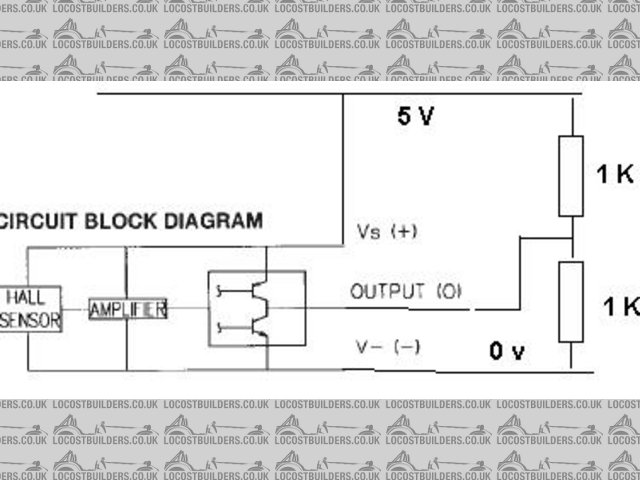
RA0 is an I/O pin that would be configured as an output since it connects to base of NPN transistor Q5.
It will send out a sequence of 0 v/5 V pulses that would make the LED1 flash.
The fact that is is 0 V is not unsual. The emitter of Q5 will be 0 V since that it connected to 0 V unless you meant another transistor?
The emitter of Q6 wil depend on LK1 and LK2 (follow connection A).
The LED flashing - is it meant to do that when you power it up to indicate the speedo healer is working?
It looks to me that it will only flash when you have input pulses and they have been converted to the new frequency since the LED is connected to the
output.
[Edited on 7/11/08 by 02GF74]
|
|
|
Mr Whippy
|
| posted on 7/11/08 at 11:42 AM |
|
|
quote:
Originally posted by mistergrumpy
Don't beetles run on 6V too?
[Edited on 7/11/08 by mistergrumpy]
early ones did, mines 12v but does have a generator and separate regulator.
|
|
|
mistergrumpy
|
| posted on 7/11/08 at 12:10 PM |
|
|
Thanks for the help O2. The LED used to flash when the car was just stood still. I've had it on the axle stands running and it still
doesn't flash.
|
|
|
02GF74
|
| posted on 7/11/08 at 12:21 PM |
|
|
quote:
Originally posted by mistergrumpy
Thanks for the help O2. The LED used to flash when the car was just stood still. I've had it on the axle stands running and it still
doesn't flash.
That doesn't seem right.
Do you have instructions?
Without knowing the PIC code, I would guess that the device could have a power up diagnostic mode or the LED may flash whey it is being programmed but
that seems unlikely since programming is done via the rotary switches.
RA0 defo lloks like output - follow the trace from the liine named OUTPUT and the LED is connected to that.
So back to when it used to flash.
1. did it flash at same rate?
2. did it aways flash when unit was turned on
3. did the flash rate change when the pulses from the sensor changed i.e. car was running on stands?
4. was it connectd to the sensor?
5. is it connectedto the sensor now?
6. is the sensor working?
7. what is the output connected to?
8. did you chjhange anything? wiring, switches etc.
Only explanation I can give for it flashing was if the sensor was in such a position that it could detect the on/off location of the bolt or the thing
it was sensing and a tiny amounht of movement would sned it in either state - but unlikley since there is a bit of filtering on the input plus
problaby edge detect filtering in the PIC code.
|
|
|
mistergrumpy
|
| posted on 7/11/08 at 01:07 PM |
|
|
When it did flash:
1. Always flashed at same rate
2. Flashed when ignition was switched on if I remeber rightly
3. I don't remember the flash rate changing with speed
4. It was connected to the sensor
5. It is connected to the sensor
6. Not sure on sensor working. Its the syandard Kawasaki hall effect?
7. I'm trying to think of what I changd in that system and all I can think of is that the rev counter counter wasn't working can't
remeber what was wrong and I found an earth wire totally unconnected that I'd forgotten about. I can't really remember the precise moment
the LED stopped working though.
I've just tried running the engine on the stands again but no light.
Instructions say that the LED should flash at 1Hz whilst the car is in motion. This would show that the speedo corrector has set itself for the type
of speedo signal that is present and is receiving a valid signal.
I can accept that the sensor may not be close enough (though much closer would be too close) but the fact is that the LED did flash once upon a time.
I'm wondering if the sensor itself is knackered now?
|
|
|
mistergrumpy
|
| posted on 7/11/08 at 04:55 PM |
|
|
I tested the speedo sensor as per Haynes manual and when waving a screwdriver in front there was no voltage detected so I've beento the
scrappies and got another and still no difference. testing shows it to be exactly same as the first. Puzzled now.
|
|
|
02GF74
|
| posted on 7/11/08 at 08:56 PM |
|
|
quote:
Originally posted by mistergrumpy
When it did flash:
1. Always flashed at same rate
2. Flashed when ignition was switched on if I remeber rightly
3. I don't remember the flash rate changing with speed
tht doesn't make sense. I am assumingthe line labelled output is the signal that goes to the speedo, if so, the corrected pulses come out of
RA0 and will flash the LED according to a scaled up/dwon frequence of the inout (from the sensor).
What is S1 and S1 set to?
Have you ever had this working i.e. conveertin pulses ffrom the sensor to the speedo?
What does autoset do?
Hall effect sensor should have 3 wires:
1. supply, usually up to 9 V, hence presumably the circuit has a 8.5 V source
2. 0 V
3. Signal
|
|
|
mistergrumpy
|
| posted on 7/11/08 at 09:34 PM |
|
|
Yep. Output is the converted signal on its way to the clocks. Input is from the sensor.
Instructions say to start off with set S1 to position 2 and S2 to A (Autoset). Install link LK2 and drive the car for a minute. Speedo shouldn't
work. LED should flash at 1Hz whilst car is in motion which shows that the speedo corrector has set itself for the type of speedometer signal and is
also receiving a valid signal. If the LED doesn't flash install link LK1 instaed of LK2 and try again.
I've definitely had the LED flashing before it must have been whilst the car was on stands again at the bottom of the drive.
The sensor is standard Kwak item with 3 wires as you say but the corrector has a 12V feed
[Edited on 7/11/08 by mistergrumpy]
|
|
|
02GF74
|
| posted on 8/11/08 at 07:45 AM |
|
|
quote:
Originally posted by mistergrumpy
Instructions say to start off with set S1 to position 2 and S2 to A (Autoset). Install link LK2 and drive the car for a minute. Speedo shouldn't
work. LED should flash at 1Hz whilst car is in motion which shows that the speedo corrector has set itself for the type of speedometer signal and
is also receiving a valid signal. If the LED doesn't flash install link LK1 instaed of LK2 and try again.
I've definitely had the LED flashing before it must have been whilst the car was on stands again at the bottom of the drive.
The sensor is standard Kwak item with 3 wires as you say but the corrector has a 12V feed
Ok, it seems to be one of these clever one that self-calibrates. I'm pretty sure you need to drive for one mile, not one minute. Driving for a
given length of time will tell the unit nothing since it does not know the distance you travelled in that minute.
When self-adjusting, the LED will flash at 1 Hz; these pulses should still go to the speedo but with a typical speedo running at 1,000 pulse per mile,
this would be equivalent to just over 3.5 mph; most speedos don't have the needle move until above 10 mph (a digital speedo would).
Do you have link to instructions for the speedo?
Can it be run without the self calibration?
If you don't calibrate it, does if default to some value?
If your sensor is hall effect, it needs to have a magnet go zooming past it.
I'm kinda running out of ideas to be able to troubleshoot it remotely - are you able to contact supplier?
The circuit has diode so you won't have killed it by connecting it incorrecly; likewise it has regulated 5 V supply which you have measured so
we know that part is ok.
Is the PIC in a socket? It may be worth taking it out and pushing it back in in case there is bad contact - unlikely but can happen.
Then put switches in autoset mode without any inoput connected - put your DVM to measure voltage on the LED - it may be that the LED has blown,
unlikely but ...... ok, that is not it as you have already measured voltage at RA0.
I just noticed the bit about having valid signal, bold above.
Disconnect sensor and the speedo from the circuit.
Connect LK2. Get at 1 K resistor and connect it to 12 V. Then touch the other end of resistor very quickly to the input -this will simulate a signal
- the 1 K resistor will limit current and voltage.
[Edited on 8/11/08 by 02GF74]
|
|
|
mistergrumpy
|
| posted on 8/11/08 at 11:05 AM |
|
|
Ah ha, now we're getting somewhere. I did the resistor in wire thing like you said. This resulted in a voltage of around 12V. I touched it onto
the input terminal (after disconnecting the wire from the sender) like you said and there it was, the LED started flashing 
So, I measured the voltage being sent to the sender which was only around 5V. So am I right in thinking that maybe this is too low to power the
sender and is resulting in nowt being sent to the corrector.
By the way. Thanks very much for getting me this far its very much appreciated. I'm not that great with electrics, I've got books and that
and the theory seems to go down but not the practical.
|
|
|
02GF74
|
| posted on 8/11/08 at 02:50 PM |
|
|
that's good news - it shows you have not fried the circuit!
next step is to figure out how to get a signal from the sensor.
I am not familiar with the sensor you are using but if itis Hall effect, it may be something
like this
Supply is 4.5 - 10.5 V, typ 7.0 V so it should really work with 5.0 V.
Try this.
1. connect 5.0 V to device.
2. Connect output to two 1 K resistors beween to 5 V and zero, as below.
Put DVM to read volts on ouput then bring a magnet close to the sensor - you should see a voltage change; maybe as little as 0.5 V.
Note that you must get the power supply the right way round otherwise the sensor ill be toast.
You could then try connecting the 8.2 V supply to the sensor from LK1 on the board. DO NOT CONNECT SENSOR TO 12 V.
BUT can we check it is definitely a Hall effect? An inductive type sensor has 2 wires and is magnetic i.e. it should grab a steel
screwdriver close to it; some have an electro magnetic coil so would have 3 wires.
Any chance of posting a picture of the business end of the sensor?
Do you have Kawasaki wiring diagram showing the sensor?
[Edited on 8/11/08 by 02GF74]
Rescued attachment sens.JPG
|
|
|
mistergrumpy
|
| posted on 9/11/08 at 07:01 AM |
|
|
The sensor is the 3 wire magnetic sensor type then sorry, not a hall effect. It normally works by the sprocket passing by it and in the Haynes it says
to test it by hooking up 12V power to 2 terminals with a 10K resistor on one and then earth the remaining terminal and to move a screwdriver across
the front of it which should register a voltage of some sorts. Neither of the 2 sensors I have do that but I thought it's maybe a bit much if
both were out.
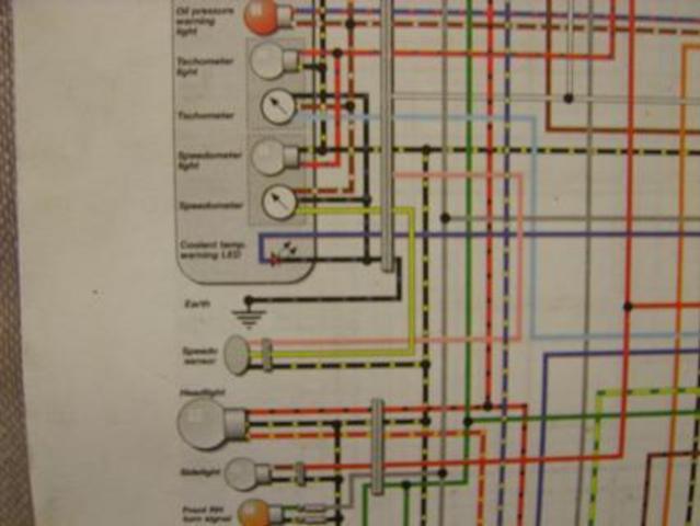
Here is a picture of the circuit diagram for the speedo:
Image deleted by owner
The sensor is the yellow, pink and earth wired thing bottom left. It feeds off the speedo clock.
Here is the sensor:
[img][/img]
|
|
|
02GF74
|
| posted on 9/11/08 at 11:00 AM |
|
|
quote:
Originally posted by mistergrumpy
the Haynes it says to test it by hooking up 12V power to 2 terminals with a 10K resistor on one and then earth the remaining terminal and to move a
screwdriver across the front of it which should register a voltage of some sorts. Neither of the 2 sensors I have do that
Here is a picture of the circuit diagram for the speedo:
hang on, let me put my glasses on. 
nope, no good, diagram is still fuzzy.
most digital camera will have a manual fixed focus, go to camera set up menu and select a close fixed focus, e.g. 0.5 m.
then hold camera about 0.5 m from the diagram before pressing the photo button.
I can seethe 3 wires but cannot tell for sure what thay are all usedfor; pink disappears after it reaches the thick grey bar - is that a connector?
or is it a screen?
(NB if you do destroy sensor, there is loads on ebay, see: 180294037799)
What bike is it from? Googling has shown a Kawasaki sensor with different wire colours.
Can you measure resistance between all 3 wires?
Does it contain a magnet inside - i.e. can it pick up a paper clip?
It may have an electromagnet re: the power supply - which sets up a magnetic field - a second coil will detec changes inthe field why a ferrous object
goes by - this will generatethe signal voltage.
when you have connectd the sensor to a voltage supply, can it pick up a paper clip then?
Are you sure you are connecting it correctly?
|
|
|
mistergrumpy
|
| posted on 9/11/08 at 07:56 PM |
|
|
Okay. Took me the best part of 3 hours to work out how to focus the camera right 
Description
The sensor is from a 98 C model ZX9 and it can only be plugged into the loom the one way so that'll be right. There's also continuity from
the plug right up to the plug that goes into the clock.
The grey bar on the picture represents the plug I gather, not sure why it doesn't show where the pink wire goes. I've just took the clocks
apart but it just feeds into a resistor then off to a diode and I can't see further.
The sensor itself is magnetic before and after it is plugged into the loom and it'll pick up a screw no worries.
I've just plugged everything in and put the battery on. Something that I noticed is that the yellow wire feeds a steady 4.67V or so but the pink
wire fluctuates from 0.02 to 0.01 to 3.67 then back to 0V and then just keeps doing that again and again?
The earth is fine when I did a continuity check to the chassis.
I think it must be a sensor problem. I've tried both though, and they respond the same.
|
|
|
02GF74
|
| posted on 10/11/08 at 07:30 AM |
|
|
so sensor:
black/yellow = 0 v
yellow = supply, 4.7 V (or 5 V as good as damit)
pink = output
now the output is fluctuating between two voltages 0 and 3.7 V all the time.
does the speed of fluctuation change when you wave a steel object near the sensor?
It may be hard for you to see this with a DVM as there is some delay in updating the display.
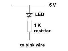
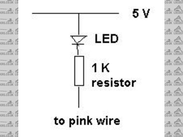
You may want to have a LED connected to the 5 V supply with a 1 K resitor connected to the pink wire - you will see if the flash rate changes.
(my current thinking, and it may be wrong, is that the sensor supplies a train of pulses whose frequency is representing the speed.)
Remember when you wrote this: The LED used to flash when the car was just stood still.
wot you wrote above explains as to why - the sensor is giving out a constant stream of pulses so the unit thought is was in calibration mode. this
may make auto-calibration interesting!
[Edited on 10/11/08 by 02GF74]
Rescued attachment tled.JPG
|
|
|
mistergrumpy
|
| posted on 10/11/08 at 09:59 PM |
|
|
Daily update then.
After some more fiddling I've found that this fluctuating voltage is actually coming from the speedo corrector "input" terminal.
I can stop this voltage appearing at the input terminal by removing the LK1/LK2 link.
Getting really confused now! It's (you tell me) as though a capacitor is charging then discharging maybe?
The U2U sent regards the ZX12 limiter isn't applicable to the ZX9 as it had no limiter. No speedo wire ever goes to the ECU even.
|
|
|
02GF74
|
| posted on 11/11/08 at 07:11 AM |
|
|
So what I wrote about the sensor is b*ll*cks since I was not aware you had it connected to the corrector, it makes more sense now.
You should be able to test the sender by connecting it to 5 V supply - you can get that off one of the pins on LK2, wiggling metal and measuring the
output voltage.
Incidentally, how are you supplying power to the sensor?
LK1/LK2 links select between 8.2 V and 5 V supply to the input stages - how does manual describe these links?
I'll wager the pulses you are seeing are not due to some capacitor charge/discharge but are coming from RA2. I have an idea asto why this may
but but this is conjecture so I'll keep quiet.
Do you have a link to documentation about the circuit? Sorry progress is slow as it is a lot of guesswork without knowing the code inside the PIC

What do instruction say about switches S1 and S2?
You've tried different switch positions ABCDEF (you may need to power off/on since the device may only readthem when it is starting to run the
code.
|
|
|
mistergrumpy
|
| posted on 11/11/08 at 07:42 PM |
|
|
The corrector was bought off Ebay by a lad who makes them from the plans up there ^ and includes some home printed instructions so they're
rather limited.
The only reference made to LK1/2 is at the start when it says if the LED doesn't start flashing then try installing link on the other i.e.1 or
2.
Power to the sensor is supplied down the yellow wire from the clocks and also earths via the clocks too.
S1 and S2 are decribed as being the "correctors" in that S1 is for single units and S2 is for tens of units. They can also be used to
correct speedo lag on digital speedos. During initial set up, he first thing it says to do is set S1 to 2 and S2 to A and after the LED flashes for
recognition of a valid signal it says to set S1 to 0 and S2 to 0.
There is no online instructions that I could show you sorry.
Don't apologise for the time it's taking mate, I feel quite bad for keep mithering you.
|
|
|
mistergrumpy
|
| posted on 12/11/08 at 09:38 AM |
|
|
I think your RA2 idea might be right. I've just put the multimeter on this pin and the voltage goes from 0.01V to 5.03V every 5 seconds or
so.
What's your idea then?
|
|
|
mistergrumpy
|
| posted on 12/11/08 at 11:33 AM |
|
|
RA2, RA3 and RB0 are all acting in the same manner with the voltage fluctuations.
|
|
|
mistergrumpy
|
| posted on 13/11/08 at 02:13 PM |
|
|
Image deleted by owner
The brown and white wire leading into the speedo is 12.23V, the yellow wire leading out is 5V. Testing resistance on the clocks when they are not
plugged into the loom shows an open circuit between the brown and white and yellow.
|
|
|
mistergrumpy
|
| posted on 16/11/08 at 11:55 AM |
|
|
Wahey! Just to round this off, I've sorted it. Summat clicked last night around midnight after reading something totally unrelated earlier that
mentioned a yellow wire. I was getting off to bed and so had to get dressed and out to the garage to check.
I'd cut into the pink wire! I thought yellow was the feed off the clocks but it's the other way around
Just got to calibrate the thing now. Just hit around 200mph sat on the drive Bloody thing doesn't want to tune down.
Massive thanks to 02GF74 for his constant help and to Mackei23B and Matt.C for answering my U2U's. Cheers lads
|
|
|