blakep82
|
| posted on 29/3/09 at 10:16 PM |

|
|
hazard light circuit?
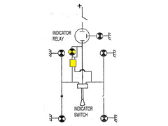
how does this look?
 
Description
the yellow bulb symbol is the hazard warning light, the yellow square is a double pole switch. i know the drwings a bit messy round the double pole
switch, but how does this look to everyone? will it work ok?
the reason for using the DP switch is to stop both left and right indicators connecting when the switch is off, but they both have the same power
input
________________________
IVA manual link http://www.businesslink.gov.uk/bdotg/action/detail?type=RESOURCES&itemId=1081997083
don't write OT on a new thread title, you're creating the topic, everything you write is very much ON topic!
|
|
|
|
|
Hellfire
|
| posted on 29/3/09 at 10:21 PM |

|
|
Doing it this way means the Hazards will onyl work when the (I presume Ignition Switch) is made... Hazards need to work with power direct from
permanent live. Indicators use switch (ignition) feed.
Using our diagram will help - it's on the website under MISC/HELP.
http://hellfire.locostsites.co.uk/bladehelp.htm
Steve

|
|
|
omega 24 v6
|
| posted on 29/3/09 at 10:22 PM |

|
|
I doubt the hazard warning light will work. It'd be better in the output side of the switch with an earth connection (doesn't have one in
your drawing) and a diode to stop feedback from the indicator.
If it looks wrong it probably is wrong.
|
|
|
blakep82
|
| posted on 29/3/09 at 10:29 PM |

|
|
of course, it wouldn't work  never mind... never mind...
thanks steve, will have a good look at that.
was also looking at cbs's hazard switch kit.
http://www.cbsonline.co.uk/hazard-switch-kit-hazkit-1840-p.asp
seemed a bit expensive, but perhaps the easiest way.
________________________
IVA manual link http://www.businesslink.gov.uk/bdotg/action/detail?type=RESOURCES&itemId=1081997083
don't write OT on a new thread title, you're creating the topic, everything you write is very much ON topic!
|
|
|
Paul TigerB6
|
| posted on 29/3/09 at 10:32 PM |

|
|
As above, you really need the hazards to work with the ignition off.
Take a permanent live feed into the flasher unit and then a feed out to both the hazard switch and a 4 blade relay as per
here
pin 30 - flasher feed in
pin 87 - to indicator switch
pin 85 - switched live
pin 86 - earth
Turning the ignition on forms a circuit between 30 and 87 so the indicator switch gets power. Pretty simple to do really
|
|
|
Blackbird Rush
|
| posted on 30/3/09 at 07:22 AM |

|
|
quote:
Using our diagram will help - it's on the website under MISC/HELP.
http://hellfire.locostsites.co.uk/bladehelp.htm
Steve
Steve,
What software did you use to make up the diagram? need to do a similar thing as i'm making my loom at the moment.
Cheers
Ash
|
|
|
tendoshingan
|
| posted on 30/3/09 at 08:20 AM |

|
|
Hi
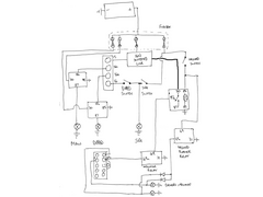
ok here's my hand drawn diagram of the wiring to a sierra stalk.
I did it fully locost as I had some spare relays and didn't want to use the sierra switch.
You can see the stalk is the part at the bottom left that shows, 49a, L, R.
This can be replaced with your 3 pole switch.
 
Proper wiring diagram
|
|
|
Hellfire
|
| posted on 30/3/09 at 09:13 AM |

|
|
It was done agaes ago - it's a combination of a PC Application especially for Boards (cant recall it's name - it was 4 years ago or more)
and Photoshop.
Steve

|
|
|
Hellfire
|
| posted on 30/3/09 at 09:19 AM |

|
|
quote:
Originally posted by tendoshingan
Hi
ok here's my hand drawn diagram of the wiring to a sierra stalk.
I did it fully locost as I had some spare relays and didn't want to use the sierra switch.
You can see the stalk is the part at the bottom left that shows, 49a, L, R.
This can be replaced with your 3 pole switch.
Whilst I can understand it would work - the two relays could and would work concurrently potentially causing a problem.
The Hazards also need placing on there own fuse as the power draw could be as much as 8 Amps. You dont really want a short out in a bulb/lamp to wipe
out your Hazard Circuit.
You are much better off using one relay - Ignition Feed tripping out the Permanent Feed and Vica Versa - that's the reason we used a Durite
Switch.
Steve

|
|
|
tendoshingan
|
| posted on 30/3/09 at 10:55 AM |

|
|
Hi Steve
quote:
Whilst I can understand it would work - the two relays could and would work concurrently potentially causing a problem.
If you notice on the diagram the hazard switch connects to another relay stopping the indicator relay, so they can never work concurrently, the
permanent hazzard switch trips out the ignition switched indicator.
The hazard lights are also on their own fuse.
I did this so that I could use my own switches to control the hazards and not have to pay lots for a regular one.
Ian
|
|
|
Blackbird Rush
|
| posted on 30/3/09 at 06:43 PM |

|
|
quote:
Originally posted by Hellfire
It was done agaes ago - it's a combination of a PC Application especially for Boards (cant recall it's name - it was 4 years ago or more)
and Photoshop.
Steve
Ta for the info, i'll hunt out something to turn my notes into a nice diagram....
|
|
|


