Tris
|
| posted on 19/1/11 at 11:21 PM |

|
|
Electrical help - Gear position to Voltage - ZX12
Hi all,
Been racking my head with this for an hour or so now and wondered if anyone had either done this before or know how.
I am trying to create a circuit which converts the gear position on my ZX12 to a voltage between 0 and 12v for my dash's analogue input. The
ZX12 has a rotary switch built within the gear box which effectively switches one of 7 wires to ground depending on what gear you are in (six gears
and neutral).
Has anyone done something similar before ?
Cheers
Tris
|
|
|
|
|
belgian2b
|
| posted on 19/1/11 at 11:41 PM |

|
|
Hello ,
give a look at this , it may help :
http://www.angelfire.com/wa3/r.miklos/shiftindicator/gearindicator.htm
Gerardo
|
|
|
locogeoff
|
| posted on 19/1/11 at 11:57 PM |

|
|
Not done it myself but it's only electricity, so
The first thing you need to find out is what are the threshold values for the analogue signal to represent each gear on the dash or is there an
element of programming that can be performed in the dash to map the output voltage of the switch to the gear engaged. The term switch to be defined
as
12V connected to Rballast connected to dash input also connected to the dash input is the following resistors and wires connected in parallel
-RNeutral-wire for neutral
-R1-wire for 1st
-R2-wire for 2nd
-R3-wire for 3rd
-R4-wire for 4th
-R5-wire for 5th
-R6-wire for 6th
So you form a potential divider between 12V and earth (0V) formed from the ballast resistor and one of the resistors depending on which gear your in,
as the wire for each gear is earthed when that gear selected, and presumably open circuit when not selected.
The trick will be to select the correct resistor values to get the desired effect. i.e. display gear and not push too much current through the dash or
potential divider.
[Edited on 20/1/11 by locogeoff]
|
|
|
rf900rush
|
| posted on 20/1/11 at 08:06 AM |

|
|
Firslty, Do you need to keep the ECU informed of gear position.
The voltage for each gear and if neutral is used.
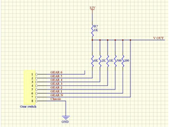
A simple resistor network may work.
Something like this.
 
ZX12 Gear
Some resistor are not common values
6K may need to be 6.2K
2K (2.2K)
500ohm (470)
200ohm (220)
Martin
|
|
|
Tris
|
| posted on 20/1/11 at 09:56 AM |

|
|
Thanks all for your replys,
Just what i am after though, i was trying to keep all of the feeds live into the bikes ECU but then i suppose as i am only switching to ground it
shouldn't matter if i piggyback this additional circuit into the bike loom.
My RaceTechnology has configurable voltages per gear, but thinking about it - i wonder how much the +12v feed would fluctuate when the engine is
running ? (which would then obviously alter 'slightly' all of the individual gear voltages). Is it worth throwning in a voltage regulator
to regulate down to 9v, before then doing the resistors to ground ?
Cheers
Tris
|
|
|
rf900rush
|
| posted on 20/1/11 at 11:30 AM |

|
|
Here is the internal circuit of a hacked 2000 ecu
LINKY
Inputs are on the ECU's 5volt circuit
Any mods that goto the 12v may or, more likely BLOW UP your ECU
If you measure the volts from the 1st gear wire you may find a range of suitable voltages come out from the ECU.
1st will alwasy be 0V
The rest will feed back through the R047 390ohm into the 1st gear wire.
You need to make sure your Dash input does not load the ECU.
And More importantly NO 12v GETS TO THE ECU INPUTS.
Martin
|
|
|


