Ety
|
| posted on 13/4/21 at 01:09 PM |

|
|
Windscreen Wiper with Park
Finally got round to posting this, hope it helps.
Notes on using the Lucas 14W wiper motor with alternative switches.
The Lucas switch for the above motor is a "Flick" or lever toggle switch that may not appeal to all. There are other switches that
present a different appearance and include a wiper icon, for example, the commonly available Durite 0-646-50 rotary switch1. See Useful Links
below.
When using a Lucas 'flick' switch, the system is configured to use dynamic braking. It shorts the motor windings to ground. This cannot
be done with simpler three contact switches used in this example.
Thus alternative wiring schemes are required to make it work, some of these are shown below.
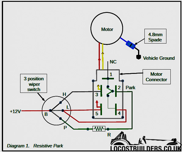
For resistive park, first remove the blue (-12V) motor wire from the horizontal terminal (T1) in the plastic connector, see above. Using a 4.8mm
Lucar spade connector make a direct connection to the vehicle ground (-12V.) The following notes assume this is done. The +12V should be supplied
via it's own fuse rated at no more than 7.5A for each system. If windscreen washers are also run from the same fuse then no more than 10A
Note; direct connections can be made to the motor connector terminals T1-5 using insulated 4.8mm Lucar
crimp connectors, also known as spade terminals.
Resistive Park Operation (2 Speed motor)
a) Switch position 'H' (high speed.)
The diagram above is the motor connector front view, and shown with the wiper switch in the 'H' position
(solid line.) Power is fed directly to the motor yellow wire (via T3) and the motor runs at high speed.
b) Switch position 'L' (low speed.)
With low speed selected, power is supplied directly to the motor T5 via the switch B to L.
H and P are both isolated from +12V.
c) Switch position 'P' (park.)
When P is selected +12V is fed to the T5 terminal (which is now isolated from +12V B) via R, at a limited
current, and T2/T4 using the motor internal change-over (c/o) switch. When an internal cam actuates the
c/o switch, power to the motor is turned off, as T2 is switched to T1, and the motor, now running at a
limited speed, stops in the park position.
d) In the drawing above, the internal motor switch is shown in the 'not actuated' position. The switch
changes to the dotted line position (T1) when actuated by the cam as it reaches the park position.
The Durite wiper switch used has 'make-before-break' switching between L and P this prevents any
sudden discontinuity of the 12V feed when changing from L to P.
With well installed wiper systems using small wiper blades, such as might be found on Caterham or Westfied Super 7 style cars, the motor will have
enough 'run-on' to go past the park position and continue. With the Lucas switch, the dynamic braking configuration prevents this.
By adding resistance R in series with the park 12V feed we can employ current limit braking.
For example, if the motor used 2A under normal load then a 2 ohm series resistor would cause a 4V drop in the voltage applied to the motor, which will
reduce the current and cause the motor to slow. This slower speed will prevent 'run-on' and the wipers will stop at the park position.
The resistor wattage rating, for the example above, would be 8W plus a reliability margin. A readily available 2.2 ohm 25W panel mounted resistor is
priced at £1.75 from;-
http://cpc.farnell.com order code RE05379
These resistors are specified for an operating temperature range of -55 to 200°C, so use in the engine bay would not be a problem. Example values
available are 2, 2.2, 2.7, 3.3 Ohms.
The exact resistor value will depend on the how loaded the wiper motor is. Remember that when the alternator is charging the voltage may be between
13.8 and 14.4V. Without the engine running the voltage could be 11.7V or less if freezing conditions. Thus finding a suitable resistor value will
need some experiments. For experimenting one can use cheaper 10W wire wound resistors that are available in a range of values, for example;-
www.maplin.co.uk/p/wirewound-10-watt-33-ohm-resistor-h3r3
Using resistive current limiting has two minor advantages. If the resistor were to fail, go open circuit, auto park will not work, but one can still
manually stop the wipers in the park position. Also, by limiting the park current through the change-over switch, the contacts will last longer.
Warning: If using the resistive park system you must ensure that the motor has parked properly, if not it may have stopped in a stalled condition.
This would mean that current is flowing in the circuit and not switched off. If this should happen it could result in a flat battery, or worse,
overheating of wiper motor or wiring.
The resistive park system is not recommended for vehicles that are regularly out in wet conditions and would have frequent wiper use.
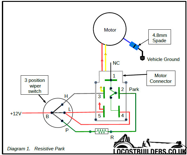
If one is prepared to use manual park, i.e.switch the wipers off when the wiper blades are at a park position, then Diagram 1 simplifies to that
below.
It is possible to use dynamic braking if a relay is added. This requires more wiring than the Lucas switch owing to the relay actuator coil
connections and the relay inter-connects.
See Useful Links below
For a well integrated motor control solution, with the most functions and the least wiring see the littelfuse.com link below and view the Electronic
Windshield Wiper Switches Series 4, Part No. 75600-04. These have 2 speed, park, intermittent wipe, push to wash, (with 2/3 wipes), on a single round
knob which is similar to the one on the Durite switch.
For single speed motor use, just wire H and L together with no connection to T3 giving Park/Off - Wipe - Wipe.
Single relay park operation has been used in some installations. See the following diagram (D3) for use with the Durite 0-646-50 rotary switch.
Diagram 3 below shows the wiring for a single relay system which implements dynamic braking to stop the wiper motor at the park position. The relay
is a change over type with one contact pair made when not energised On being energised the alternative contact is selected.
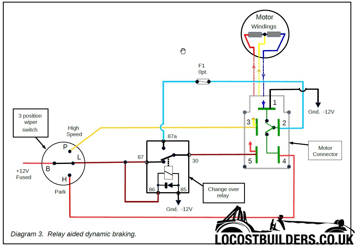
Single Relay Operation with Durite switch.
Low Speed.
The diagram above shows the wiper switch with L selected (solid line), the relay is energised, by 12V from the link between terminals 87 86.
Terminal 5 of the wiper motor receives +12V via the relay contacts 87 & 30 which is then fed to the motor low speed section and returned to ground
(-12V) through terminal 1 of the motor connector.
Internal park switching in the wiper motor is shown with the motor not at the park position, so motor terminals 2 and 4 are connected. This does
nothing as the relay terminal 87a is not connected and there is no 12V feed to T4. The same occurs when the internal park cam actuates and connects
terminal 2 and 1, grounding relay terminal 87a has no effect in the not connected state.
High Speed.
When P is selected at the wiper switch +12V is applied directly to terminal 3 of the wiper motor and the current returns to ground via the motor
winding and terminal 1.
When the motor park switch toggles, whilst running in H, there is no effect as terminal 87a is not connected due to the relay still being energised
also T4 has no +12V.
At first glance it would appear that the relay would no longer be energised because the +12V has been removed from the relay terminals 87/86, due to
the wiper switch being moved from L to P. However, the +12V applied to the T3 motor winding causes +12V to appear on terminal T5 of the motor
connector and hence on terminals 30, 87 and 86 thus keeping the relay energised. Relay currents through 86 to 85 (ground) are typically 0.13A (at
+12V) so are small compared to the motor current flowing in terminals 3 & 1. Relay currents measured using a Lucas SRB501 or Ripaults P00701
relays, see links below.
Warning:
An important point to note, the 3 position Durite wiper switch used1 does not have make-before-break switching between L and H this means that the
relay time delay for drop out (change-over) is important to ensure that the relay does not change over while switching from low to high speed. If it
does drop out during switching then this is the same as Relay Failure described below.
Bench testing with the Durite 0-646-50 rotary switch showed that the Lucas SRB501 or the Ripaults relays would drop-out when switching from L to H.
No matter how fast one tried to switch using the Lucas relay it would always drop-out. It was occasionally possible to get the Ripaults relay (with
internal diode) to not drop-out, but not with any reliability suitable for use.
Increasing the relay drop-out time could be done by adding a capacitor to the relay terminal 86.
However, when the power energising the relay is removed the collapsing magnetic field (which operated the contacts) causes voltage spikes at terminal
86. If we wish to add a large value polarised capacitor then it is necessary to ensure that no large negative voltage spike can appear at terminal
86. This is done by using a relay which has a built-in diode, see 12voltplanet product P00701 in links. If your car uses any Electronic Control
Units (ECU's), for example fuel injection control, then it is probably a good idea to use relays with built in diodes anyway.
Adding an extra components or even an extra relay, as some systems have done, just means there are more additional items to fail. Additional
components can be avoided if we are prepared to accept that the wiper switch knob must be rotated anti-clockwise rather than the normal clockwise
rotation.
It was mentioned above (section c of Resistive Park) that the Durite switch has 'make-before-break' switching between L and P. This can
be used to solve the problem of relay drop-out when switching from low speed to high speed wipe. This is achieved by connecting T3 to P and T4 to H
as shown in diagram 3 above. This provides 'make-before-break' switching between low and high speed wipe. By applying +12V to T3 before
disconnecting +12V from the switch L terminal we are assured that T5 will have +12V via the motor winding thus keeping the relay energised.
Park Mode
Switching the wiper switch from L to Park (H) removes the relay energising voltage, the relay now connects terminal 30 to 87a. Now the motor is
powered in low speed mode via +12V looped from T4, the motor internal park switch, to T2 then the relay 87a to 30 and back to T5 on the motor.
When the motor actuates the park switch T2 is then connected to ground at T1. This causes T5 to be grounded, via the T2 loop described above, as is
the other end of the motor windings which is directly connected to T1. This shorting of the motor windings causes the dynamic braking and the motor
is brought to a rapid halt. When low speed is selected from the Park position the relay connects T5 to 30 thus removing the winding short
condition and the motor is again powered at low speed.
Relay Failure
Warning: If the relay energising coil were to fail, go open circuit, then the 87a 30 contact pair would be permanently connected. This would mean
that a) low speed would not work, b) in high speed, each time the motor park switch actuated there would be extra high current flowing because T5 now
becomes grounded.
In such a situation, continual operation could damage the motor park switch contacts, which would then need to be replaced.
This highlights the need for a correctly rated fuse feeding +12V to the wiper switch.
One possible useful addition could be an optional fuse in the park loop, shown as F1 opt., if the +12V fuse blew or it was suspected that the relay
was faulty then F1 could be pulled, thus breaking the park loop. Fuse, F1, could then replace a blown +12V fuse, if necessary. Once the park loop is
disconnected this will allow high speed wipe with manual park to work, assuming that the motor is not faulty. This gives some wiper operation until
repairs could be completed.
© J Hasler 2016
A list of 5% & 10% low ohm resistor values are given below.
Standard 5% (E24) Resistor Values Standard 10% (E12) Resistor Values
ohms ohms
1 1.0 1.1 1.2 1.3 1.5 1.6 1.8 1 1.0 1.2 1.5 1.8
2 2.2 2.4 2.7 2 2.2 2.7
3 3.3 3.6 3.9 3 3.3 3.9
4 4.3 4.7 4 4.7
Useful Links
www.s-v-c.co.uk/wiper-systems/
www.duriteparts.com/durite_products/switches_and_indicators
www.asap-supplies.com/catalogsearch/result/?q=4.8mm+spade+terminal
http://cpc.farnell.com/welwyn/wh25w2r2/resistor-ww-25w-2r2/dp/RE03427
http://uk.rs-online.com/web/p/panel-mount-fixed-resistors/1073879/
www.europaspares.com/rotary-wiper-switch-3-position.html
www.carbuildersolutions.com/uk/2-speed-rotary-wiper-switch
www.carbuildersolutions.com/uk/windscreen-wiper-motor-plug-with-flyleads
www.ebay.co.uk search for Durite-Rotary-Wiper-Switch
www.littelfuse.com/industries/commercial-vehicle/cole-hersee/switches/windshield-wiper-
switches.aspx
www.123spareparts.co.uk/car-parts/Electrics/c-TecDoc-100010?q=wiper
www.ttiinc.com/page/home (search for 75600-04)
Internal wiper motor park switch.
www.minispares.com/product/Classic/Electrics/Switches,%20stalks/520160A.aspx
Good description of manual switching & motor operation.
http://www.mgb-stuff.org.uk/wiper3.htm
Relay operated (partly tested by writer.)
http://forum.britishv8.org/read.php?8,28327
http://vitessesteve.co.uk/LucasStuff/Triumph-2-speed-wiper-wiring
www.12voltplanet.co.uk/relay-guide.html
www.12voltplanet.co.uk/change-over-relay-12v-30a-supression-diode.html
www.duriteparts.com/durite_products/relays_and_flasher_units/12_volt_change-over_relays
www.autoelectricalspares.co.uk/lucas-srb501-28ra-relay-12v-2030a-1395-p.asp
www.ebay.co.uk/ Search for Lucas SRB501
[Edited on 13/4/21 by Ety]
[Edited on 13/4/21 by Ety]
[Edited on 13/4/21 by Ety]
[Edited on 13/4/21 by Ety]
|
|
|
|
|
MadMaxx
|
| posted on 14/4/21 at 03:44 PM |
|
|
Having seen you have experience on the matter:
I have Ford Sierra mk 2 '87 stalks with Lucas wiper motor. I connected the stalks according to the scheme find on forum, but if I power up the
wiper motor, the washer does not work. If I disconnect the power to the windshield wiper control lever, then the windshield washer works and the
wipers seem to slowly rotate.
I suppose that pushing the washer pump button I should contemporary be activated the wipers, but it doesn't.
To better explain: pin 53C is connected to the negative pole of washer pump. If I disconnect pin 54 from ignition live, washer pump works.
🤔 Any tips?
[img] [/img] [/img]
[Edited on 14/4/21 by MadMaxx]
My re-building diary:
http://www.llcc.it/YetAnotherForum.NET/default.aspx?g=posts&t=13448
|
|
|
|