Baldrick
|
| posted on 16/6/06 at 05:11 PM |

|
|
Electronic Dizzy & Coil - wiring?
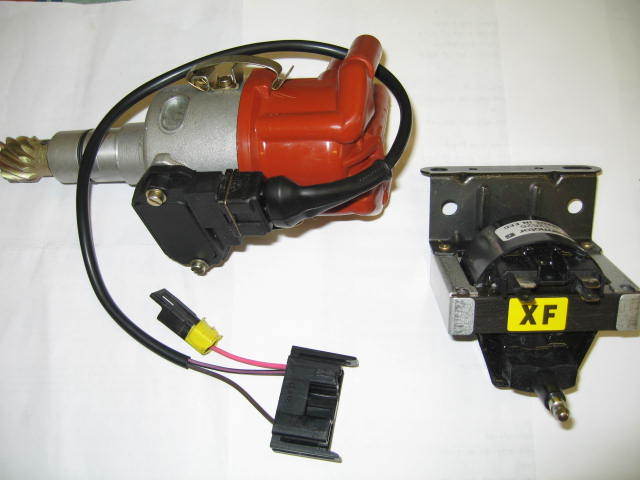
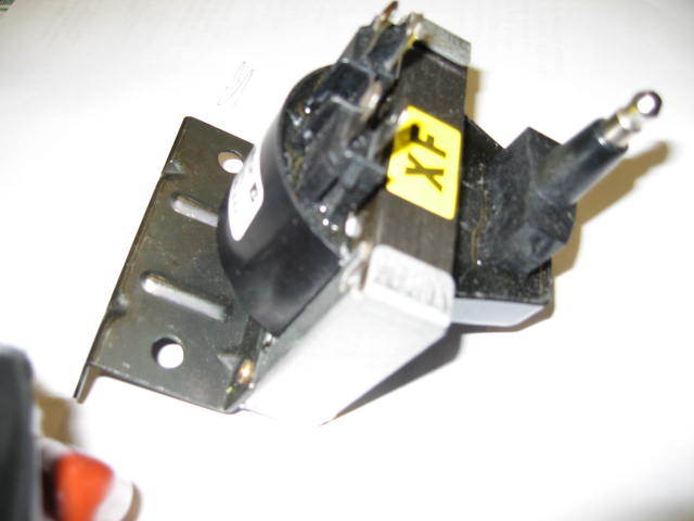
I am replacing my old points type distributor with a Bosch electronic one & new Coil.
The Dizzy has a plug with a connector having 2 wires (black/pink & brown) which attach to spade connectors on the coil. The black/pink also has a
short pink flying lead with a male spade connector.
Anyone any idea what goes to where and how I wire this in to my existing loom? Is the pink my tacho feed?
Pictures attached (hopefully)..
[img]http://www.locostbuilders.co.uk/upload/IMG_0241[1].jpg[/img]
[img]http://www.locostbuilders.co.uk/upload/IMG_0243[1].jpg[/img]
OK, I can't post the pictures.....
[Edited on 16/6/06 by Baldrick]
|
|
|
|
|
SeaBass
|
| posted on 16/6/06 at 06:15 PM |
|
|
Hi Brod,
My suggestions would be as follows;
Pink/brown + pink flyer is +ve...
Black being the switched -ve to the coil by the ignition module...
The setup looks very similar to what I'm running but you have a modern style coil.
The pink flying lead will be the ignition switched +ve supplying the coil and the transitor module.
In order to run the tacho you'll have to tap the -ve side (black wire)...
This is all my guess at the setup!!!]
Did you get it from a chap on ebay??
distpic1
distpic2
[Edited on 16/6/06 by SeaBass]
|
|
|
Baldrick
|
| posted on 17/6/06 at 09:18 AM |
|
|
Thanks James,
Makes sense now. Off to the Garage to give it a go!
|
|
|
Baldrick
|
| posted on 19/6/06 at 07:38 PM |
|
|
I seem to be finding trouble fitting the dizzy with enough free space to adjust for timing. as fitted the electronics module sits at the back by the
inlet mani and the side entry cap exits forwards. Will not fit with the cap exiting in any other direction. Any ideas?
|
|
|
Peteff
|
| posted on 19/6/06 at 09:48 PM |
|
|
Is there a No1 segment mark on the rim of the distributor when you take the cap off? As long as the rotor points at this when the unit is fitted you
can have the cap in any direction. Push it in with the cap removed and see how far the rotor turns, then turn it back from the mark by roughly the
same distance and fit it in the orientation you want.
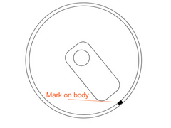 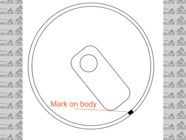
Rescued attachment dizzy.jpg
yours, Pete
I went into the RSPCA office the other day. It was so small you could hardly swing a cat in there.
|
|
|
Baldrick
|
| posted on 20/6/06 at 09:06 AM |
|
|
Yes, I did that with the no 1 cylinder mark. My problem is the electonics module and the side entry dizzy cap makes it only phyiscally fit with the
cap facing forward. then the electonics module fouls the inlet manifold giving only 1 or 2 degrees of adjustment. I'm going to try and get a top
entry cap which will sort it out I think
|
|
|