sgraber
|
| posted on 13/9/07 at 04:23 AM |

|
|
Little rocker switch with LED - Crazy bugger!
HELP!
I have a rocker switch that I intend to use for my headlights (low beams). It has a bright blue LED that I want to have come one when the high beams
are engaged. The switch itself is for the low beams, but the high beam switch has no light therefore this blue LED light should come on when I switch
the high beams on. If only I could get it to work... 
I get the LED to light, or the headlights to come on, but not both at the same time! 
EARTH_ - supply power to LED?
LED
LOAD-----\ - ground to earth?
\
SUPPLY---| - power from relay?
I apply power to the SUPPLY and take the LOAD to ground and the switch triggers the headlamp relay. Bingo headlamps, but no LED.
When I ground the EARTH side nothing happens at all.
If I then apply power to the EARTH side while the supply (from relay) also has power - no LED and headlamp relay still works.
but when I apply power the EARTH and remove the SUPPLY power, then the LED lights up but the headlamps go out....
Does this make sense to anyone?
My headlamp relay switches to ground if that makes any difference.
I found this little diagram that explains the switch, even though the rest of it is not like my situation.

Steve Graber
http://www.grabercars.com/
"Quickness through lightness"
|
|
|
|
|
Aboardman
|
| posted on 13/9/07 at 05:15 AM |
|
|
take the power for the led off the load side of the switch and not a seperate feed.
|
|
|
stuart_g
|
| posted on 13/9/07 at 06:10 AM |
|
|
I don't think it is possible to do what you want to with this sort of switch. The light on it is supposed to come on when the switch is in the
on position and not an indicator for a totally different switch.
Connect the switch like this:-
Supply = permanant 12v
load= connect to relay coil for low beam.
Earth= connect to an existing earth cable or to the chassis.
The led is wired internally so it comes on when the switch is on therefore supplying power to the load terminal. I think you'll find the led is
wired accross the load and earth terminals.
Hope this makes sense.
Stu.
|
|
|
dan__wright
|
| posted on 13/9/07 at 08:27 AM |
|
|
earth to switched side of relay, other side to ground, then wire the coil contacts of the relay into the full beams, when full beam is on the switch
is grounded which will turn the led on 
FREE THE ROADSTER ONE
!!
|
|
|
02GF74
|
| posted on 13/9/07 at 09:57 AM |
|
|
can you post the wiring forthe switch? and how the LED lamp is wired in the switch?
I am guessing whay you descrive is a three positon swtich that has 2 out puts, lets call them A and B, one input, let;s call that I.
postion 0
A and B not connected to I
position 1
A connected to I
positon 2
A and B connected to I.
so if thiss is the case, connect 12 V it I.
side lamps to A
main beam to B
LED to B.
|
|
|
sgraber
|
| posted on 13/9/07 at 06:49 PM |
|
|
I confess. I don't have a clue about this!
Here is a diagram of what I have so far, with lines MISSING for the switch. Maybe someone would be so kind as to finish the drawing?
Low Beam relay is on Left Side of Diagram and when energized provides power to hi-beam relay coil so that hi-beams can only be activated when lo-beams
are engaged...
Something about the coil side of the relay wired to the switch and the positive side of the hi-beam wired to the LED?

Steve Graber
http://www.grabercars.com/
"Quickness through lightness"
|
|
|
stuart_g
|
| posted on 14/9/07 at 12:02 PM |
|
|
My solution is to change the function of each switch and wire it as per the diagram attached. That way the blue led will function as it is supposed
to.
I have shown the internal wiring of the switches also.
[Edited on 14/9/07 by stuart_g]
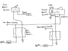 
Rescued attachment img016.jpg
|
|
|
sgraber
|
| posted on 14/9/07 at 01:32 PM |
|
|
That is a very simple change indeed.
I will try it this weekend.
THanks!
Steve Graber
http://www.grabercars.com/
"Quickness through lightness"
|
|
|
iiyama
|
| posted on 14/9/07 at 06:33 PM |
|
|
30A fuse on the lights???  Holy crap! the cabling I have is only capable of 16A! Holy crap! the cabling I have is only capable of 16A!
If its broke, fix it. If it aint broke, take it apart and find out how it works!
|
|
|
sgraber
|
| posted on 14/9/07 at 06:41 PM |
|
|
quote:
Originally posted by iiyama
30A fuse on the lights??? Holy crap! the cabling I have is only capable of 16A!
Will I save some weight by swapping out to the 20Amp fuses?
But seriously, What gauge wire you using? I use 14ga wire to the lamps from the relay. It's about a 4' run.
Steve Graber
http://www.grabercars.com/
"Quickness through lightness"
|
|
|
stuart_g
|
| posted on 14/9/07 at 08:16 PM |
|
|
just fuse it to suit you're application. The wiring stays the same. I only put 30A because the first diagram had it. If you're wire is
rated at 16Amps put a 15amp fuse in instead. simple really.
|
|
|
iiyama
|
| posted on 15/9/07 at 08:52 AM |
|
|
That was my intention, but when I saw that the drawings above had 30A fuses I thought that maybe thats what was required for the lights. Got me
worrries for a minute!
If its broke, fix it. If it aint broke, take it apart and find out how it works!
|
|
|
Spyderman
|
| posted on 15/9/07 at 02:36 PM |
|
|
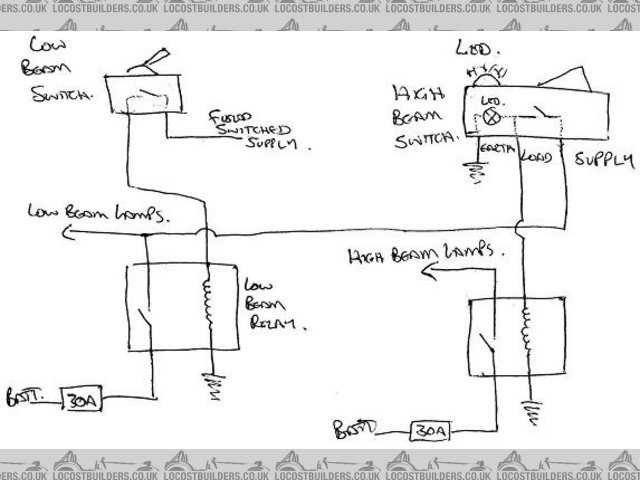
I was thinking along the lines of using a double pole relay to switch both the main beam + and warning light earth. All that needs changing is the
relay. The switch is also reconfigured so that the LED has a live feed constantly instead of only when switch is on. This enables main beam warning to
show when beam is flashed without lights being on.
Very similar to Stuarts diagram.
Hope this makes sense.

Hmm, no image.
Try this.
Wiring
[Edited on 15/9/07 by Spyderman]
Spyderman
|
|
|
sgraber
|
| posted on 19/9/07 at 07:26 PM |
|
|
I've printed out your diagram and will try to set it up that way.
Many MANY thanks!
Graber
Steve Graber
http://www.grabercars.com/
"Quickness through lightness"
|
|
|