jabbahutt
|
 posted on 25/9/08 at 07:15 AM posted on 25/9/08 at 07:15 AM |

|
|
should be simple for someone
Morning all
Well after my adventures with the fan over ride switch I now have success!! The fan can be overidden using the switch and the bulb on the dash comes
on
Only a small niggle left now. The led in the switch won't turn on
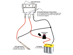
There are 3 connections on the back
1. power to the switch
2. outgoing to the appliance
3. an earth which I believe is for the LED
As I have now taken power to the dash bulb off the realy pin to the fan so it comes on if overidden or if the rad switch comes on I have no output for
the switch.
So I connected it to earth and hey presto the switch works.
However if I connect the LED earth pin to earth the lED won't light up. If I swap the earth to this pin the fan obviously doesn't work
but the LED does.
I thought if both the output and the LED connections went to earth it would work but it doesn't.
So is there a simple way to get the LED to come on when the switch is turned to on?
Any help much appreciated, I know it's really treivial and daft but I'd like to know why it doesn't work so at least I've
learnt something.
Thanks
Nigel
|
|
|
|
|
jabbahutt
|
| posted on 25/9/08 at 07:35 AM |

|
|
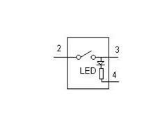
sorry if it helps here is a diagram
[img]
 
led switch
[/img]
My question is if there is no accessory why cant pins 3 and 4 just both go to earth?
If it because the output needs somekind of load? if so what could I use to fool the switch?
Many thanks, I know this isn't particularly interesting.
Nigel
|
|
|
Mr Whippy
|
| posted on 25/9/08 at 08:18 AM |

|
|
the real question is what happened to pin 1  ??? ???
|
|
|
jabbahutt
|
| posted on 25/9/08 at 08:21 AM |

|
|
Shame on you Mr Whippy I thought you'd posted a solution 
I thought I was going to benefit from your electrical knowledge so I could get this sorted.
You've let me down Mr Whippy
|
|
|
minitici
|
| posted on 25/9/08 at 08:41 AM |

|
|
You have not described what you have done very clearly!
I can't figure out anything from your description regarding what is and isn't connected to what......
Really need a good diagram of what is connected to the relay, switch, fan and dash indicator.
In the diagram for your generic wiring to the illuminated LED switch - If you do not connect anything to Pin 3 (12V to accessories) then the switches
LED should still illuminate when the switch is turned on. [So long as you have the centre pin 2 connected to a +12V source and Pin 4 connected to -12V
earth]
It sounds like you may be using the switch to switch to earth rather than feeding power to the relay.
|
|
|
Paul TigerB6
|
| posted on 25/9/08 at 08:41 AM |

|
|
quote:
Originally posted by Mr Whippy
the real question is what happened to pin 1  ??? ???
Dont you know nothin'?? The pixies took it clearly!!! Some people............ I dunno......... tut  
|
|
|
jabbahutt
|
| posted on 25/9/08 at 08:56 AM |

|
|
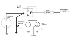
[img]
 
my fan wiring
[/img]
This is how it is currently wired. Yes I'm trying to use the switch as a switch earth.
Looking at the diagram of the switch though I cant see why the switch output to the accessory and the switch earth can't just be run to earth to
get the switch both to work and the LED to function.
Is this enough info or am I still missing something?
Thanks
Nigel
|
|
|
r1_pete
|
| posted on 25/9/08 at 09:11 AM |

|
|
You are switching the negative from the fan, so you have no live feed to the switch to power the LED.
|
|
|
MikeRJ
|
| posted on 25/9/08 at 09:14 AM |

|
|
The reason it doesn't work it that the switch is intended to switch the live side of the load. When you use it to switch the ground side of a
load, there is no potential difference to operate the LED.
There is no easy way around this, unless you can take the switch apart and reverse the polarity of the LED. Connecting a live wire to Pin 4 will then
illuminate the LED when the switch is operated (and hence the relay grounded).
The other option is to use another relay, e.g. supply a live feed to one relay coil via the switch, the other side of the coil is grounded. You then
use the contacts on that relay to ground the coil if the main relay.
|
|
|
jabbahutt
|
| posted on 25/9/08 at 09:25 AM |

|
|
Thanks.
So before I moved the bulb on the dash to pin 87 it was connected to the accessory out on the switch and the LED worked even though it ultimately went
to earth straight after the bulb.
So couldn't I put some sort of load back onto that pin from the switch and get it to work that way?
Appreciate everyones help with this.
Nigel
|
|
|
02GF74
|
| posted on 25/9/08 at 09:47 AM |

|
|
From what I can tell, pins 2 and 3 are the switching part and pin 4 is to supply 0 V to the internal LED.
As the clever people have said, you are switching ground so the LED does not receive the 12 V its needs to illuminate (not strictly true as there is
the relay coil in the circuit with the LED but the voltage is so low that we can ignore it).
So you have following options:
1. rewire your circuit - you are a bit stuck since the radiator switch I am guessing has body connected to earth.
2. ignore the switch lamp
3. rewire the switch internals
4. use another relay (£ 2 from maplin)
And what has happened to pin 1?
If you are lucky, the switch as a LED bulb that you can revers then supply 12 V to pin 4. I would check that the switch internals are as below as you
may end up shorting 12 V to ground! 
From your info. the internals fo your switch appear to be like this:
 
Rescued attachment switch2.JPG
|
|
|
jabbahutt
|
| posted on 25/9/08 at 09:51 AM |

|
|
many thanks
So last question as it looks like I'm going to ignore having an LED
Could someone provide an explaination/diagram of how to add the extra relay as I already have a spare
Thanks
Nigel
|
|
|
richardlee237
|
| posted on 25/9/08 at 10:10 AM |

|
|
Assuming pins 85 and 86 are the relay coil pins and are not internally connected to anything else.
You need to put the the 2 switches in parallel in the positive feed to pin 85.
Switch pin 2 to battery
Switch pin 3 to relay pin 85
Switch pin 4 to earth
Relay pin 86 to earth
Connect the rad fan switch across switch pins 2 and 3
The disadvantage of this is that both switches have permanently live connections.
Quote Lord Kelvin
“Large increases in cost with questionable increases in performance can be tolerated only in race horses and women.”
Quote Richard Lee
"and cars"
|
|
|
02GF74
|
| posted on 25/9/08 at 10:17 AM |

|
|
quote:
Originally posted by richardlee237
Assuming pins 85 and 86 are the relay coil pins and are not internally connected to anything else.
You need to put the the 2 switches in parallel in the positive feed to pin 85.
Switch pin 2 to battery
Switch pin 3 to relay pin 85
Switch pin 4 to earth
Relay pin 86 to earth
Connect the rad fan switch across switch pins 2 and 3
The disadvantage of this is that both switches have permanently live connections.
hmmm, this assumes the radiator switch ahs two isolated contacts. I do not know what switch Jab.... is using but the ones I have seen use the body as
one of the contact so are connected to ground.
I would suggest seeing if the switch can be taken apart and modified internally - or use another switch?
oh, if you want diagram on how to use switch but with 2nd rely, then remind me as I gotto do some work 
[Edited on 25/9/08 by 02GF74]
|
|
|
richardlee237
|
| posted on 25/9/08 at 10:52 AM |

|
|
As 02GF74 says, if rad switch is grounded then you can't put it on pos side.
For 2 relays see attached picture
Quote Lord Kelvin
“Large increases in cost with questionable increases in performance can be tolerated only in race horses and women.”
Quote Richard Lee
"and cars"
|
|
|
richardlee237
|
| posted on 25/9/08 at 10:57 AM |

|
|
.jpg)
Quote Lord Kelvin
“Large increases in cost with questionable increases in performance can be tolerated only in race horses and women.”
Quote Richard Lee
"and cars"
|
|
|
richardlee237
|
| posted on 25/9/08 at 10:59 AM |

|
|
Link
Quote Lord Kelvin
“Large increases in cost with questionable increases in performance can be tolerated only in race horses and women.”
Quote Richard Lee
"and cars"
|
|
|
jabbahutt
|
| posted on 25/9/08 at 11:27 AM |

|
|
many thanks I can just get my head around that. Just need to deide if I'm brave enough to start mucking around with wiring that is currently
working just to satisfy my bloody mindedness not to be beaten by some wire and invisible electrickery
|
|
|
Paul TigerB6
|
| posted on 25/9/08 at 11:43 AM |

|
|
quote:
Originally posted by jabbahutt
many thanks I can just get my head around that. Just need to deide if I'm brave enough to start mucking around with wiring that is currently
working just to satisfy my bloody mindedness not to be beaten by some wire and invisible electrickery
Sort it out after SVA then mate???
|
|
|
02GF74
|
| posted on 25/9/08 at 12:39 PM |

|
|
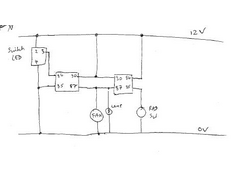
here is circuit.
basically another relay (on left) is put in parallel that is switched from positive.
 
Rescued attachment fan3.JPG
|
|
|


