Possible crank ring fault, opinions please
corrado vr6 - 21/8/21 at 06:58 PM
Hi,
I have a MK4 golf ARL PD150 1.9 TDI
The engine has been rebuilt and ever since itís been re-fitted it has had an issue with not revving past 2000rpm.
This has gone on for months so some may remember a previous post. I am still trying to diagnose the issue. My diagnostics (VCDS) only comes up with a
crank sensor implausible signal.
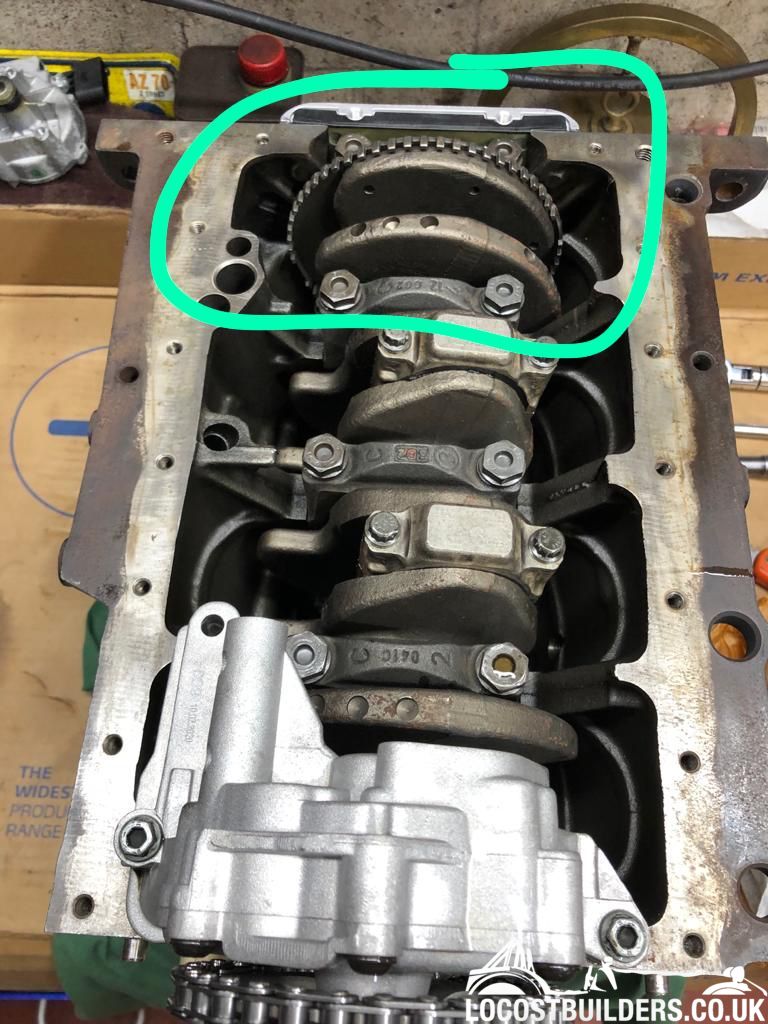
I have been looking back through my pictures of the build and have one picture of the crank ring reluctor ring.

I think I can see something, at this stage I donít want to influence anyoneís view so I wonít mention where just yet.
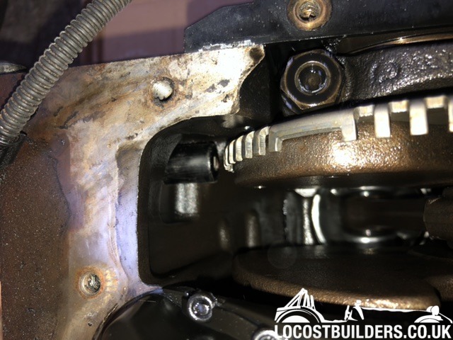
I have done a video using an endescope in the crank sensor hole. I again feel I can see a fault but wonít mention where so not to sway an opinion.
Could anyone that is mechanically minded mind watching a very boring video of a crank ring please let me know their thoughts, before I commit to
taking the sump off 🤦🏻‍♂️
Video
https://youtu.be/mgggR7M2KD4
Thanks in advance
[Edited on 21/8/21 by corrado vr6]
Schrodinger - 21/8/21 at 08:17 PM
I'm not sure of this engine but there seems to have been something fouling the lugs on the ring and taken the odd small bit out but I
wouldn't have thought the damage would cause your problem unless it was the sensor touching the teeth. I assume the ring has not been modified to
have the 2 gaps for tdc, and that is what the management system is expecting.
corrado vr6 - 21/8/21 at 09:14 PM
Thanks for your reply!
Luckily I have two engines so I have another to compare too. I can confirm that the gaps in the two gaps are meant to be there.
I feel I can see a bent tooth in the video at around 3 mins in just after one of the big gaps.
perksy - 21/8/21 at 09:28 PM
If it won't rev past 2000rpm is it going straight into 'limited operation strategy' and throwing the code ?
Implausible signal sounds like, Dodgy wiring on the crank sensor, the sensor itself or an issue with the crank trigger?
High revving XE's sometimes developed cracked trigger wheels on the crank and mounting the wheel and sensor on the front of the crank used to be
the cure
But if yours was really bad surely it would be reluctant to start in the first place?
When you removed the sensor was there any damage to it?
Also Isn't there a known cable shielding issue on these?
Do we have anybody local to you with an oscilloscope or can you do live data and check the crank sensor waveform?
Apologies if you've already tried/answered these questions on another thread
corrado vr6 - 21/8/21 at 10:40 PM
Thanks!
I have a spare engine loom hopefully turning next week to check the wiring.
You are absolutely correct that this car does have a shielding issue which is explained on the Ross tech site.
However this car was a driving running motor with a damaged camshaft. This engine got removed and another put in its place after a full strip and
rebuild, including the crank being polished.
No damage to the sensor when removed
If anyone has access and the knowledge of using an oscilloscope I am based in Winchester Hampshire and your help/knowledge would be appreciated sooo
much!
Thanks for the replies
Greg
Sanzomat - 22/8/21 at 06:36 AM
Not an expert but that toothed wheel doesn't seem to have any issues that would mess up the signal. I see what you mean about the bent tooth but
can't see that being enough to throw the signal pattern out (although an oscilloscope would prove that). My vote would be sensor or wiring. If
the gap between sensor and teeth is too big it can upset the signal so check that any sealing washer or suchlike wasn't any thicker and if a new
sensor was used that it is the same length.
If that is okay then I'd be looking at the wiring. Check the grounds on the shield wires. Maybe run the signal wire separate from other wires as
far as possible.
corrado vr6 - 22/8/21 at 07:27 AM
Here is a video of what is happening, the engine will get up to 2000rpm no further then bounce up and down.
Video from outside the car
https://youtube.com/shorts/rqt_M87zUHI?feature=share
Video from inside the car
https://youtube.com/shorts/e8nA17Yaguw?feature=share
Video of the car revving past 2000rpm, this has happened probably 3 times now but can never be replicated. In this video it was being run from a Jerry
can to rule out the fuel in the tank. I have since run it from a Jerry can and cannot replicate this. The car has also revved another time when I
removed the exhaust downpipe to rule out the cat. I have again removed the exhaust so many times but cannot replicate it revving. I have also fitted
another ESP sensor to remove the ESP light which has worked but as soon as it hits 2000rpm the ESP light comes on.
I guess as it has revved would this mean itís electrical vs mechanical?
I should add I have also swapped the ECU for an immobiliser free one, to rule out my original ECU.
Video of car revving
https://youtube.com/shorts/E-TV30CLe3M?feature=share

[Edited on 22/8/21 by corrado vr6]
RedAvon - 22/8/21 at 08:21 AM
Does this help?
http://wiki.ross-tech.com/wiki/index.php/16705/P0321/000801
Looking more likely to be electrical as a result of the rebuild. Something incorrectly connected, poor ground, poor connection etc.
The above specifically mentions Golf.
Hope that helps.
Ian
corrado vr6 - 22/8/21 at 09:30 AM
Thanks Ian for the link.
I have come across this TPI before but after extensive google searches I cannot find anyone who has actually needed to do it.
I have posted about it on other TDI forums and no one has replied which suggets its not very common.
I am tempted to try doing the re-wire though as it seems simple enough and would makes sense that its electrical as it has revved a handful of times
in the past but can never be replicated.
I have just read that by connecting pin 3 of crank loom to multimeter and then to the battery negative that if the voltage is greater than 1v then I
should do the TPI. I guess I need to get out there with the multimeter again
corrado vr6 - 22/8/21 at 02:04 PM
So I have and checked and I have 2v on terminal 3
I also have 2v on pins 1 and 2.
Assuming the black is the earth Iím guessing this should be 0?
obfripper - 22/8/21 at 07:20 PM
You're heading in the wrong direction there, the sensor is a vr type, and should have a 500 ohm resistance between pins 1&2. Any voltage at
the plug is from the vr sensor signal conditioner built into the ecu, and should not affect the signal when connected and in use.
The tpi is indicating that the shield wire is bonded to 1 of 2 inputs on the ecu, and that shield wire affects the signal if the bonded input is not
floating in the correct voltage range (likely an unintended ecu design fault).
As per the tpi, separating the input and shield wires, and then bonding the shield wire to a good earth should fix any floating input problems.
Just in case you don't have a copy of the tpi, it's here:
https://www.vwaudiforum.co.uk/forum/showthread.php/177891-1-9-TDI-AJM-PD-not-starting-replaced-crankshaft
In regards to the bent tooth, are you able to get to the sensor location with a feeler gauge and check how much further away the sensor tip is on that
tooth.
I would expect <0.5mm to have no effect, with a problem being more likely with a gap in excess of 1mm.
I don't know what tolerance vw allow for variation in the vr signal, there may just be a slight voltage drop on that tooth signal that is
throwing a signal out of range parameter, from experience some cars will run with the sensor unbolted and rattling about in the hole (with the
oscilloscope barely showing a recognisable signal), yet some won't even start if the signal is slightly out of spec.
The ring is only pressed steel, with a bit of care you may be able to bend the tooth back to position without further problems.
Dave
corrado vr6 - 22/8/21 at 07:37 PM
Hi Dave
Thanks for your extensive reply!!
Your understanding of auto electrics far exceeds mine.
I have asked on a Mk4 Golf forum to check on their PDís with ignition on if they also get 2v on pin 3.
So far everything I have managed to read online suggests I should have 0v at pin 3.
Hopefully some people come forward and Iíll get an idea of what is right or wrong
Sanzomat - 22/8/21 at 08:13 PM
Might be stating the obvious here but have you also checked the cam position sensor? I'm assuming there is one? I guess a lot of people on here
(me included!) are quite familiar with petrol engines but maybe less so with diesel? I'm assuming the VAG PD diesels use high pressure direct
injection rather than any kind of port/manifold injection. If so the injection pulse timing is more critical than on a petrol injection system. A
crank signal can only tell whether a piston is going up or down, not whether it is sucking squeezing banging or blowing. Crank sensor only is okay for
wasted spark ignition but no ignition on a diesel! The injection pulse must therefore be timed off a cam sensor?
corrado vr6 - 22/8/21 at 09:00 PM
I must admit I have never checked the cam sensor, I have tried in-plugging it to see if any change (which there was not) but thatís all. So not a bad
shout there. I guess I have never gone that route as the VCDS diagnostics has always said G28 crank sensor.
This model has a high pressure lift pump (now new) to the fuel filter and then a tandem pump run by the cam for injection timing. I have swapped the
tandem pump for what I believe was another known good pump and still the same. However if itís the cam sensor that is defective
🤷‍♂️
obfripper - 22/8/21 at 09:31 PM
As it is originally wired, pin 2&3 will always be the same voltage, once the shield wire has been separated and bonded to earth it will be 0v at
the shield wire pin, and the voltage at pins 1&2 will be of no real consequence, but should be the same between identical ecus.
The cam sensor provides a phase signal, and is used as a verification of the cam/crank sync, this can be seen on the live data block 004.4 as an
angular value, if this value exceeds +/-5.5į the engine will not start. Most pd engines run best in the +0.5 to +1.5į range, this is due to valve
timing being most efficient in this range.
The fuel injection is timed from the crank unless the crank signal fails, but only certain engine codes will run on cam sensor alone and then only in
limp mode anyway, the engine will not restart in this situation.
Conversely some pd engine codes will start on crank sensor alone, by injecting fuel on both cam phases and getting sync from which phase makes the
engine speed increase, this will bring on a fault code but no limp mode.
Dave
corrado vr6 - 22/8/21 at 09:54 PM
Thank you again guys.
I have had confirmation from another golf owner but with a BEW engine that his pin3 is 0v.
Annoyingly mine is an ARL so is a different engine code but his is still a PD engine.
Iím lost right now, Iím guessing I shouldnít be altering my loom without being sure thatís the right thing to do which sounds like it may not be.
I hopefully have a second loom coming soon which I guess the chances of that having the same fault/s is slim.
Iím unsure of my way forward, leave the sump alone as itís a mixed bag of opinions as to wether there is a bent tooth, or try adapting the loom to see
if itís an earth/shielding issue.
Itís strange it has revved a handful of times but cannot be replicated, also the times it has revved it sounds lovely!
obfripper - 22/8/21 at 10:23 PM
Have a look at this thread, similar problem to yours and was cured with a replacement reluctor ring.
https://www.vwt4forum.co.uk/threads/t5-1-9tdi-axb-cranks-no-start.1775893/post-6556845
Dave
corrado vr6 - 23/8/21 at 06:43 PM
Luckily I have an old engine lying around so I can see where the crank ring is in relation to the sensor probably a 12mm gap

I had a little play this evening. I unplugged the cam sensor, car ran but when revved sounded like it was going to cut out.
Plugged cam sensor in and thought Iíd unplug the crank sensor, this gave me a no start and a G28 no signal code on VCDS. so it can determine the
sensor is there and when it is implausible signal. I checked the bolts once warmed up slightly and now get 1v across all three pins.
Iím guessing itís going to have to be sump off. It looks difficult with the gearbox in place too! I tried using a hooked tool on my spare crank ring
through the crank sensor hole I donít think I would achieve anything accurately this way and couldnít even flex the tooth
[Edited on 23/8/21 by corrado vr6]
britishtrident - 23/8/21 at 09:27 PM
Check the air gap between the sensor and the ring.
Check the sensor wiring and polarity
If nothing apparent you would need to look at the cam and crank signals by using an oscillicope -- a cheap Owon VDS or even a Hantek
[Edited on 23/8/21 by britishtrident]
obfripper - 24/8/21 at 07:24 AM
Have you got the correct sensor? That gap looks massive, i can't help with exact dimensions as they're not present on any data sources i
have, but would expect it to be in the 0.5-1.5mm range as per most other vehicles that use a vr sensor.
Dave
corrado vr6 - 26/8/21 at 02:39 PM
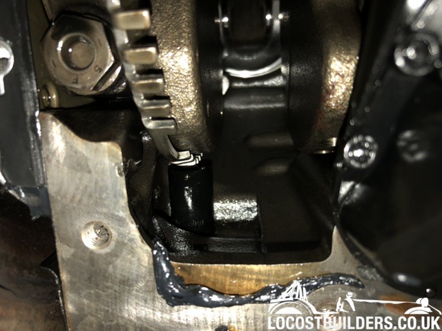
Took the plunge and took the sump off.
I reckon at least one or two teeth are bent inwards

obfripper - 26/8/21 at 05:48 PM
The clearance to the sensor appears to look better in that picture, i would check the gap in multiple places to establish if the reluctor ring is
otherwise running true.
If that is ok, then bend the damaged teeth outward to match the gap measured.
That should be enough to bring the signal back into range which will allow the fault code to be cleared.
Dave
corrado vr6 - 31/8/21 at 09:05 PM
Well tonight I got out to my lockup and bent the teeth back and replaced the sump and replaced the oil.
Turn the key and pressed the pedal.....
https://youtube.com/shorts/E-TV30CLe3M?feature=share
😎😎😎🤩🤩🤩
Thank you everyone for replying and sharing their thoughts and wisdom!


