
Car design
Anman - 30/11/06 at 05:48 PM
Hi,
I am very interested in building my own car. But I am even more interested in building one in designed myself. I am a student mechanical engineering
and have decent experience with soldisworks.
Because i dont have the time and money right now to build a car right now, i though i start designing a car of my own.
I started just copying the chassis from the book into Solidworks to get a feeling for the dimensions. But i was wondering why some design desicions
were made and why particular dimensions where chosen.
So i was wondering if you could help me with that. Maybe there is a site or a book with some basic concepts?
Also i was wondering what is the advantage of putting the engine in the rear instead of the front?
I hope you can help me.
Thanks in advance,
Anne
DIY Si - 30/11/06 at 05:57 PM
Firstly, welcome to the mad house. Most of the design decision on the Book chassis are, I believe, pinched form the early Caterhams. Also the book
chassis is very easy to improve and the book has many "discrepancies" in it regarding tube lengths and sizes. I can't remember what
it's called but there are books on the basis of chassis design, try searching Amazon.
A rear, presumably you mean a mid engined car?, will have a relatively higher handling limit, but is harder to control past that limit, compared with
a front engined rwd car. It can also allow for a wider range of engine to choose from, as any front wheel drive set up can be thrown in the boot.
flak monkey - 30/11/06 at 06:08 PM
Welcome to the site 
You will find a wealth of knowledge lurking on here, and plenty of sarcasm too. 
Chassis design is not too tricky, follow some basic rules and you cant go too far wrong. The skill comes in optimising the rigidity to weight ratio.
Obviously the chassis needs to be designed around you, your chosen engine and other running gear.
The main problem with designing your own car from scratch is bodywork. There are several guys on here who will testify to how much work goes into
manufacturing your own bodywork (alanb and sgraber to name 2).
David
PS which uni are you at?
[Edited on 30/11/06 by flak monkey]
Jon Ison - 30/11/06 at 06:11 PM
Hi n welcome........
Take a look in the "mid engined" section for some real inspiration on car and bodywork design.
Anman - 30/11/06 at 06:24 PM
Thanks for your replies.
I did mean mid engined when i said rear engined. Btw i am not stuck on mid engined, just wanted to ask something about it. Thats why i posted my
questions in the general chassis thread.
My uni is located in the Netherlands, Universiteit Twente.
russbost - 30/11/06 at 08:00 PM
Welcome to the looneybin, as already said there is much information on here along with theP***taking!
I'm a dyed in the wool mid-engine man myself (after all when was the last front engined F1 car, about 1961?) so you're thinking along the
right lines. Look back thro' some of the old stuff in the mid-engine section, I'm sure you'll find loads that's interesting.
suparuss - 30/11/06 at 09:31 PM
mid engine is the only way! just kidding, both formats have their advantages and disadvantages. i think the main design criteria for the book chassis
was to fit it into the body shape and to use specific running gear. this is where most cars devolop from, especialy scratch built one offs like some
on this site, but from a chassis performance point of view it is best to design the body work to fit the chassis rather than the other way round.
the only way to efficiently design a one off scratch built car is have the main donor parts to hand for measuring so that the mounting points and
overall size can be drawn into your 3d design programme. from there it is just a case of connecting the dots with frame work in the strongest but
lightest way possible! easy! just remember triangles are good and tetrahedrons are better! id recomend a good book on chassis design and suspension
geometry which is very important.
cheers,
Russ.
[Edited on 30/11/06 by suparuss]
Anman - 30/11/06 at 10:21 PM
Any suggestions for a good book on those subjects?
Isn't there a database somewhere with dimensions from existing engine(parts)?
iank - 1/12/06 at 02:33 AM
For starters read this -> http://www.locost7.info/files/chassis/kitcaranalysis_V2.doc
It's a good start for zero money and gives a good flavour of the kinds of things you should be thinking about when putting a chassis together, I
think it was done by cymtriks who posts here.
Then get some balsa wood strips and glue and have a play around building chassis shapes twisting them and that will give you a really good feeling for
what works. If you can get the software, you can use computer packages to get real measurements if that interests you. But computers come a poor
second for getting an instinctive understanding of what is going on.
One very good tip IMO (which I think comes from Chapman himself) is to think of the chassis as a big bracket that joins up the important bits. i.e.
get the suspension design right, and the engine/people in the right place (for weight distribution) and only then designing the chassis is the right
way round. It's packaging the important bits that leads to a lot of the design decisions your wondering about.
The advantages of mid-engined include weight distribution, packaging, overall weight, parts availability and fashion  Unless you require 100%
perfection for competition either will do an excellent job for a road/trackday car. The 911 makes a good example of what can be done even with the
worst possible basic design.
Unless you require 100%
perfection for competition either will do an excellent job for a road/trackday car. The 911 makes a good example of what can be done even with the
worst possible basic design.
There aren't many sources of accurate measurement of engines etc, but there is a scan of a dimensioned zetec drawing on here somewhere.
Hmm just found this http://www.locost7.info/files/engine/22R-2.jpg not sure how useful it would be though.
Here's a copy of the zetec drawing
http://www.locost7.info/files/engine/zetec1.jpg
[Edited on 1/12/06 by iank]
Anman - 1/12/06 at 06:39 PM
Another question i have i regarding FEA calculations.
I was wondering which programs you guys use. I have a licensed version of Ansys 9, although i dont like that program. How do you model your chassis
and how do you measure important charaterisitics (eg where are the constraints and loads)?
thanks
nasty-bob - 1/12/06 at 11:15 PM
Hi,
It's been mentioned, but there really is quite a bit of work to do before getting on to the chassis design.
You need to choose your suspension type and define the geometry. And most importantly (in terms of chassis design), decide where the dampers are to be
mounted.
Then get as many components as you can into CAD. As a minimum you will need engine, gearbox, suspension and a ergonom (driver). But the more parts you
put in the better the whole design will be refined and the better systems will work.
In terms of CAD, I use Catia for modelling but Solidworks is fine. For FEA, from my experience I-Deas is pretty user friendly. But without the
facility to benchmark results it should only be used for comparison between iterations, rather than as gospel (use a large safety factor). Use 1D
beam elements to construct the model and input forces into suspension pick up points and damper mounts. Torsional rigidity calculations will give you
an idea of whether your design is any good compared to other chassis' but you ought to focus on the suspension loads, load paths and max.
stresses.
Finally, remember that you want to build this one day. I've seen designs that are very pretty by are not manufacturable (within reason). Curved
tubes- yes they look nice but your design will no longer be a true spaceframe, and they are difficult to manufacture accurately and cheaply.
Oh....and thin walls, fat tubes are better than thick wall thin tubes- as you know, studying engineering.
All the best,
Rob
cymtriks - 1/12/06 at 11:38 PM
quote:
Originally posted by Anman
Another question i have i regarding FEA calculations.
I was wondering which programs you guys use. I have a licensed version of Ansys 9, although i dont like that program. How do you model your chassis
and how do you measure important charaterisitics (eg where are the constraints and loads)?
thanks
I used Nastran.
I wrote the input deck manually, you don't need more than one beam element per length of tube and a hand written input file is much easier to
edit to check out variations.
I restrained the model vertically at the rear suspension spring mounts and applied a load up and down at the front suspension spring mounts. I also
held the chassis vertically and laterally at the front half way across the chassis. I used a single axial restraint at the rear.
I used the displacements at the front to calculate the stiffness.
The book chassis has about 1200ftlbs per degree. Adding some extra triangulation and removing tubes that don't do much increases the stiffness to
about 2700ftlbs for a weight of 10lbs less.
Regarding mid engines this is favoured due to the lower polar moment of inertia possible with this layout. That is what the text books say.
Some designers think that the real reason is to gain traction at the start of a race, by putting more mass over the rear wheels, and to permit the
driver to sit lower by not having a drive shaft going under his seat.
Regardless of which view is correct it does not improve everything. Moving any mass futher backwards will reduce aerodynamic stability and the
tendency to oversteer suddenly at the limits of cornering.
Anman - 3/12/06 at 02:15 PM
Could you give me some more info about how you guys measure torional stiffness etc(pics maybe?). Because i was just messing around with a few very
simple test cases(eg a box) and am not sure where to place loads and constraints.
Thanks
nasty-bob - 3/12/06 at 09:43 PM
Well, I'm sure different people have different methods, but if you simply want a figure for torsional stiffness it's fairly straight
forward.
Constrain the front top mounts using ball joints. Then apply a positive vertical force to one rear top mount and a negative vertical force to the
other of the same magnitude.
Knowing the forces applied and their distance from the chassis centreline, you know the torque. Measure the displacement where the force was applied
and use trig to work out the angle.
You will find that the stiffness of the chassis will vary depending on how much torque you apply but as long as you pick a reasonable force to input
you'll pretty close, if you know the proper suspension loads for your car even better.
FEA will give you a slightly higher than actual result as it assumes that everything is perfect.
Have fun.
Anman - 3/12/06 at 10:06 PM
Ok, thanks i was thinking to complicated. What would be a realistic force to apply to the chassis (x times the car weight?)?
Fred W B - 4/12/06 at 11:18 AM
Some sources say that the required torsional regidity (in fl/pd/deg) should be numerically twice the loaded (with driver) mass in lb, while others say
three times.
But you have to decide what you think you need/can live with.
Cheers
Fred W B
ettore bugatti - 4/12/06 at 07:06 PM
Im using Autodesk Inventor 10 With Ansys integrated, very userfriendly.
[Edited on 4/12/06 by ettore bugatti]
force10 - 4/12/06 at 09:36 PM
We've cheated to a certain degree by using a very tried and tested chassis design in the locost and focusing on just developing a full body, this
should give lots of people a bit more choice when it comes to the styling of their finished car.
Maybe next year we will work on our own chassis, many of the dimensions will be determined by our choice of donor vehicle and how many components we
use from it.
I think mid engined is the way more and more kit companies will go simply due to the vast number and choice of transverse donors out there.
Good luck with your design, i hope you come up with something really refreshing and eye catching.
FT
Anman - 4/12/06 at 09:49 PM
I hope to that i can come up with some good designs. Got a lot of ideas in my head...
Only thing I really descided is that it is going to be a mid engined car.
Anman - 6/12/06 at 06:47 PM
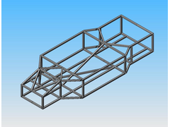
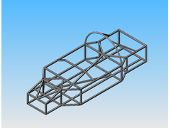
Ok I have been messing with Solidworks. The first picture is a picture of a front engined locost chassis which i abandoned but i would like your
opinions about it.
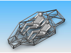
The second picture is a picture of a frame i am currently working on. It still needs some extra bracing and reving but this gives the basic idea. I
would like to know what you guys think.
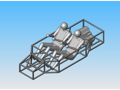
The third picture is a impression of how people and an engine would fit in this chassis, the used engine model is a bit small...


Rescued attachment frame2.jpg
Anman - 6/12/06 at 06:51 PM
Rescued attachment a.jpg
Anman - 6/12/06 at 06:51 PM
Rescued attachment test.jpg
Peteff - 6/12/06 at 06:54 PM
Is it dual control? It looks a bit short in the leg department
Anman - 6/12/06 at 07:23 PM
It's not dual control, i only have one model for a driver, would be fun though...
You are right about the leg space, i need to find a few more cm to accomodate the legs.
Anman - 7/12/06 at 06:44 PM
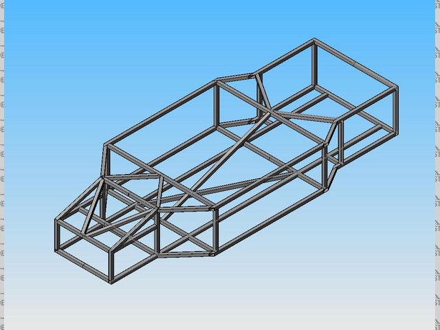
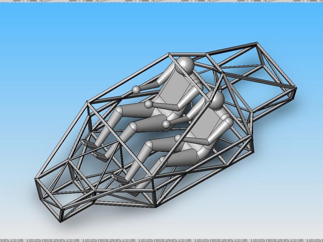
Another update, although there doesnt seem to be much interest in my efforts.
Increased the length and width to accomodate the passengers and added a rollbar.

Rescued attachment a2.jpg
flak monkey - 7/12/06 at 06:51 PM
Consider adding in two triangulated sections behind the seats. So the seat back is almost part of the chassis. The main problem with open topped cars
is the cabin is a big open and poorly triangulated box which significantly affects chassis stiffness. If you can add in a 'seat brace' it
should increase the stiffness considerably.
Its difficult to explain, but hopefully you know what I mean.
Also if you want to save weight, make the chassis out of round instead of sqaure tube, and keep all of the tube thicknesses down to 18g or 1.25mm.
I would make the roll hoop out of 50mm x 2mm tube. Inch tube really isnt enough, and doesnt look right either.
Your design has no triangulation at all at the moment. It will have a terrible torsional stiffness. Add single cross braces to each rectangular/square
in the chassis.
Nothing personal, but it might be worth reading up on tubular structures and chassis design. There are lots of books available.
Also have you designed your suspension yet? You really need this designed before you can design the chassis. the chassis should just joint up all the
mounting points you need for all of your running gear. At the moment it looks like the sides of your chassis at the front are vertical, this will mean
you will be running equal length wishbones on the front of the car (or near enough) when it is common practice to use unequal length, non-parallel
wishbones up front to give you better handling chracteristics.
David
[Edited on 7/12/06 by flak monkey]
Alan B - 7/12/06 at 06:51 PM
quote:
Originally posted by Anman
Another update, although there doesnt seem to be much interest in my efforts.
Increased the length and width to accomodate the passengers and added a rollbar.
Please don't take this the wrong way...I think a lot of people get a little blase with seeing a lot of CAD modelled images and I'm sure you
will get a lot more feedback once you start to cut some actual metal.
Also, you will get more response in the mid-engine section.....mostly the folk in this section already have a plan in mind (sort of) and discuss more
practical aspects like construction etc. rather than design theory.
See you over there.
Alan
Anman - 14/1/07 at 12:22 PM
Hi,
Well i toke the advice given by people here and decided to read some books first. I have read chassis by herb adams, im working on the automotive
chassis engineering principles and plan on reading race car vehicle dynamics next.
I have also made some rough suspension designs on paper.
Unfortunately at the moment it itsnt possible for me to buy a donor vehicle and start making really detailed designs. Non the less i couldnt resist to
design a few chassis just for the fun of it, but keeping my basic suspension designs in mind. Here are some pics of my latest wip. This design weighs
86 kg, is that a nice weight or is it to heavy?
Thanks
Anne
PS can i post multiple pictures in one post?
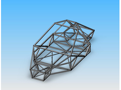
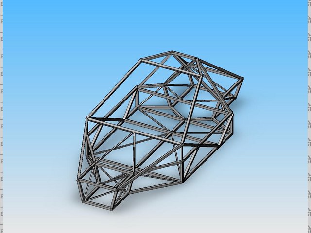
Rescued attachment d1.jpg
Anman - 14/1/07 at 12:23 PM
Side view:
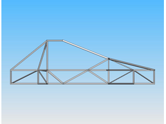

Rescued attachment d2.jpg
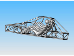
Anman - 14/1/07 at 12:25 PM
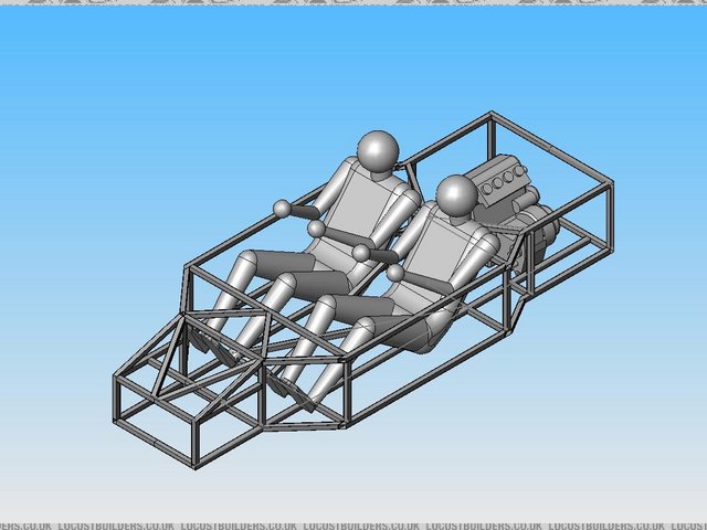
And with passengers, might need a little more space for the feet:
Rescued attachment d5.jpg
Dick Bear - 14/1/07 at 02:19 PM
Howdy Anman,
Your drawings are interesting and they make your ideas for designing a chassis easy to understand. Good work on the graphics!
I'm by no means an expert and not passing judgement on the frame as a whole 'cause there are others who have design/fab the locost frame and
know every angle, length and purpose for each piece by heart and therefore are more qualified to comment on the structure as a whole. But looking at
your last drawing I am struck by the fact that the bars above the heads of the occupants have an unsupported weld seam. If you are planning for this
to be your roll bar solution I question its' effectiveness as drawn. You might want to revisit that area so that if the need for those
protective bars are ever called into service you have a system capable of protecting the driver and a passenger. I fear what may happen now in a
turn-over situation will be more distructive to all than not having anything at all.
The great thing about drawing any system first is the ability to anticipate the forces prior to experiencing them. You are to be commended on your
efforts to do so and your eventual build will be far better because of it.
Thanks for sharing your ideas.
Dick Bear
Anman - 14/1/07 at 02:52 PM
Thanks for your reply. You were absolutely right about the rollbar, although i didnt think about it that way, more of a way to increase rigidity.
I have changed the roof and added a support beam. Unfortunatley it is starting to look a bit like a tractor

Rescued attachment d6.jpg
Anman - 13/2/07 at 07:14 PM
I am having some difficulty with trimming the weldments shown in the picture below.
Any suggestions? I am using solidworks 2006 office.
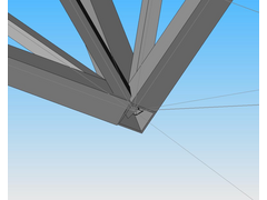

Rescued attachment i.jpg
cymtriks - 17/2/07 at 09:28 AM
quote:
Originally posted by Anman
Another question i have i regarding FEA calculations.
I was wondering which programs you guys use. I have a licensed version of Ansys 9, although i dont like that program. How do you model your chassis
and how do you measure important charaterisitics (eg where are the constraints and loads)?
thanks
I model my designs in Nastran.
I use the following restraints-
a vertical restraint on both rear spring mounts
a lateral and longitudinal restraint at centre between the rear spring mounts
a lateral and vertical restraint at the centre at the front
I use the following loads-
a vertical load on each front spring mount, one side up the other down.
The load is calculated so that 1000ftlbs per degree gives 1 inch of displacement so half that displacement gives 2000ftlbs etc.
My models use one beam element per length of tube (joint to joint). There is no need to use any more elements than this unless you want to look at non
linear (crash simulation) or vibration.
A simple model is always easier to change which is very handy for a home build.
I do not use automesh, I write the decks by hand. This means that I can number all of the elements and nodes in a way that makes sense to me. i.e. the
suspension mounts on one side could be 101 and 102 while the opposite side could be 201 and 202. The tubes could be 100+ for one side, 200+ for the
other with lateral tubes being 300+ etc. I can also use this with materials so that all ally panels are 400+ while steel ones are 500+.
Nastran gives all the element loads in a list in the f06 output file so you can easily look up which tubes are the most highly stressed using a
numbering system like the one above.
[Edited on 18/2/07 by cymtriks]
Chr!S - 21/2/07 at 09:58 PM
Hi anman! I too am building and designing a locost using SolidWorks. One thing I will say is that joint does look a bit busy!
In solidworks make it all as one part file, and DONT intersect things. You have to be clever and sketch the actual profiles it would make at the joint
and loft them from end to end. Most of the time you can get away with extrusion.
An example would be say if you had a 90 degree tube joint and wanted to add in a triangulation bar at 45 degrees into the joint. I found it much
better to do a 3d sketch of the contact surface and extrude / loft as appropriate. In general just try not to assume solidworks will intersect things
for you. Also if you build the model accurately you can use the SolidWorks plugins to perform FEA/FV solutions. If you want to improve the design
ignore FEA and think simple. Triangular truss structures are strong and light - a simple visual analysis would be far quicker.
If you keep getting the "zero thickness" error (which is not really an error) untick the merge parts box and then merge all the bodies at
the end.
I have a +4 locost SLDPRT file somewhere...
Chr!S
BlackSheep - 22/2/07 at 12:46 PM
quote:
Originally posted by Anman
I am having some difficulty with trimming the weldments shown in the picture below.
Any suggestions? I am using solidworks 2006 office.
Anman, I guess you're using the weldments option as well... I have te same problem in SW Office Premium 2007. Somehow SW has problems when the
intersection involves more than 2 surfaces. I've switched to modelling all beams as seperate parts, and building (sub)assemblies.
@Chr!s: can I have your SLDPRT? I would like to check and see how you've drawn your model. I'm still learning (the time-consuming way ;-)
).
[Edited on 22/2/07 by BlackSheep]
Chr!S - 26/2/07 at 12:21 PM
OK its written in SolidWorks 2005 but recently the university upgraded to 2006. Ive been told these are NOT backwards compatible just so you know.
Might be an idea to convert them then import if you have a previous version. Im actually going to have to correct something before I send as I
modelled the circular tube sections (the resolved sections) as splines to save time (I just needed angles and lengths) but will put something
accuracte on them probably tomorrow when I have a few minutes free as im going to be welding all day today and fabricating later....
BTW Ive looked at the weldments feature, seems to be a much quicker way of building but you still need to draw the line geometry accurately. For what
its worth I changed my extrudes to thin features and filleted the whole thing and hey presto instant weldments anyway lol


