
Duratec install progress - sump construction underway
flak monkey - 29/3/09 at 06:06 PM
Plodding on with the prep for installing the duratec. Still working on the engine at the moment, but there isnt an awful lot to do now, mainly
assembly. Managed to get it up on the engine stand yesterday which makes working on it much easier!

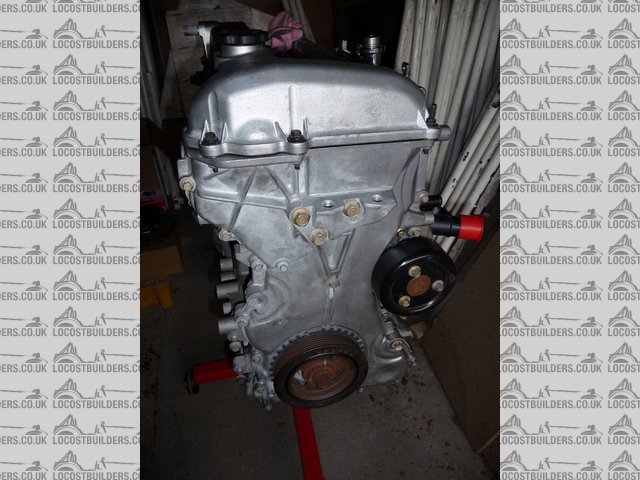
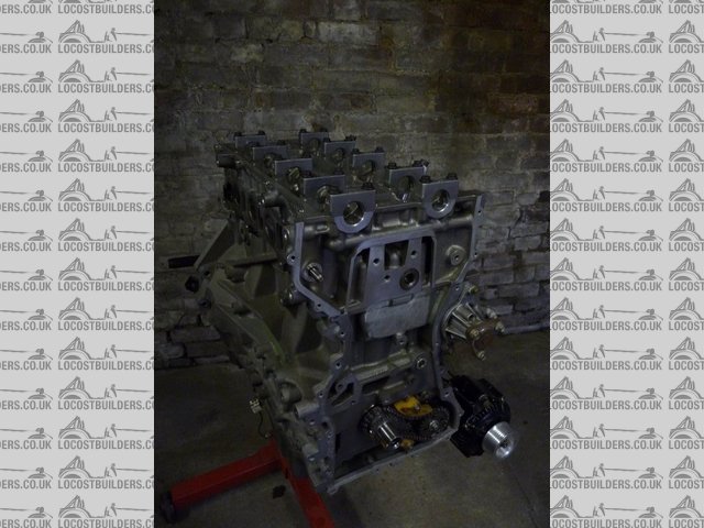
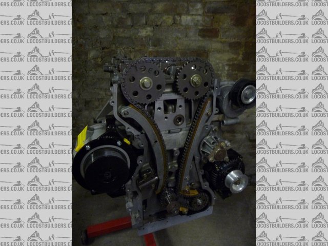
Engine front

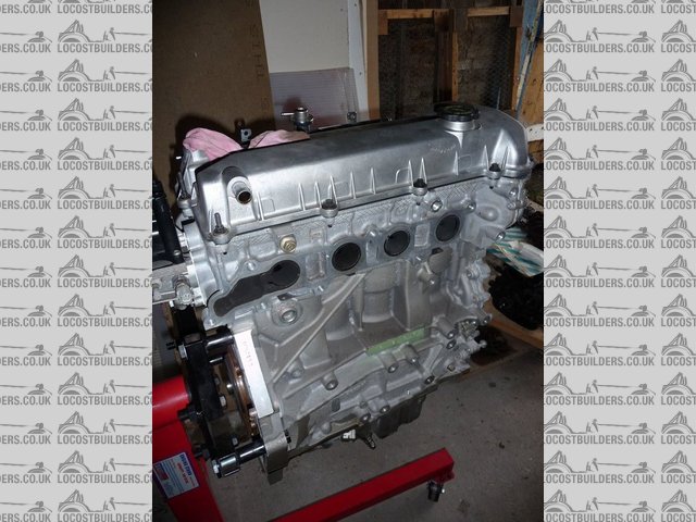
Engine exhuast side
Rather than start loads of new threads with progress I will update this one. As I am trying to do it well, but on a budget I will also keep a running
total up to date with how much its costing. Some may be suprised.....
Anyway. Made and fitted the EGR blanking plate in place of the electronic valve. They are available from Ford and Raceline/SB Dev, but I baulked at
paying nearly £40! This one cost me nothing, and 20 mins sweat with a hacksaw and file.

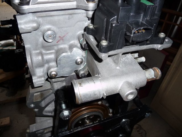
EGR blanking plate
Had an argument with someone on the duratec forum over the merits of lightweight flywheels for road use. IMO a superlight flywheel is overkill and not
needed. Especially as they are £200 plus another £200 for a clutch to suit! They are marketed as essential, but seeing as the std 1.8 flywheel only
weighs about 6kg is it worth it? What is as yet unproven is that the clutch will stand up to the power, I think it probably will but may not last as
long as a HD one.... If not, an uprated cover should do the trick. I will be using the std clutch with a 220mm plate fitted from an early mondeo (same
as zetec). If this slips I will re-drill the flywheel to take a HD pinto clutch cover.
Sump - going to use the one which was fitted to my engine, which seems to be a Transit sump and not a mondeo one. The beauty of this is that its level
with the bottom of the bellhousing within 2 or 3 mm so doesnt need any external mods. Inside its fitted with a windage tray and forward baffle. Just
needs a rear baffle fitting (welding to the windage tray) and it will be just as baffled as the Raceline sump and hold the same amount of oil. I may
add some lateral baffles as well for good measure.

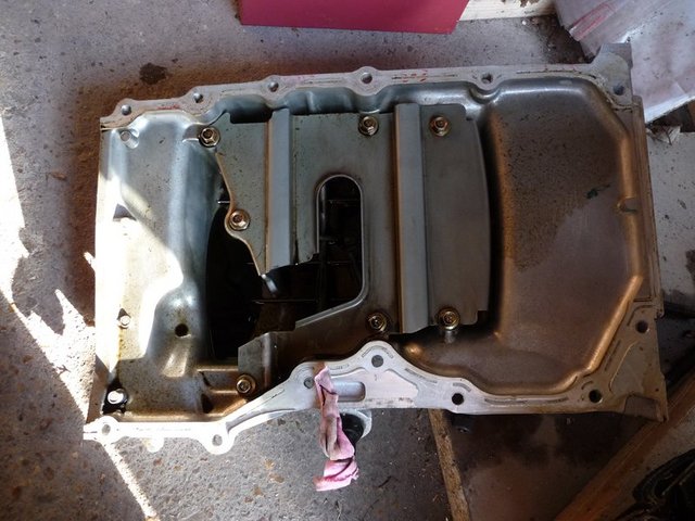
Sump inside before mods

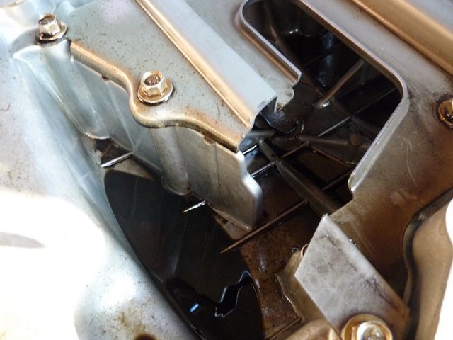
Sump inside before mods
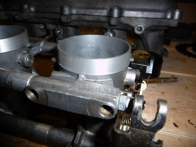
Throttle bodies and injectors. Using GSXR 750 (42mm) throttle bodies which I am going to re-space the suit the inlet port spacing on the engine. Hope
to get my inlet manifold made in the next couple of weeks, which will essentially be a 5mm steel plate with 4 stubby tubes on for attaching the
throttle bodies too. I'll post piccies once I get it done. Again cost is low compared to buying a set of throtle bodies from Webcon or Raceline.
Injectors are mounted direct into the head on the duratec, and as they are bosch ones are an easy upgrade. I have a set of 440cc/min ones on their way
over from the states (less than half the price of over here!) . I will then make a new fuel rail (same as I did on the pinto) to suit them and block
off the injector ports in the throttle bodies.
Again this was a relativley cheap way of sorting induction and fuel and neat too. More piccies to follow as I get it fitted up.
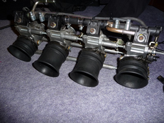

GSXR 750 throttle bodies
Lots of other stuff on the list:
Shortened prop to move the engine right back in the chassis. Needs to be about 3" shorted.
Water pipe to move the inlet on the back of the head to the front to connect to rad.
Hydraulic release cylinder spacer for bellhouing.
Mod exhuast manifold to keep same bodywork exit point, but suit new por spacing of duratec.
Make alternator bracket, also need to get hold of a small denso type alternator to fit on passenger side of engine with a 6 groove pulley on.
Running total currently about £500
[Edited on 21/6/09 by flak monkey]
dave1888 - 29/3/09 at 06:09 PM
Looks very sexy and the engines nice and clean.
Keith Weiland - 29/3/09 at 06:11 PM
This is very interesting, please keep posting details as I am going to be doing this in the future.
RichardK - 29/3/09 at 06:18 PM
Me too, cheers David
Regards
Rich
James - 29/3/09 at 07:15 PM
Flak,
With my current lack of cash situation I'm living my upgrade life through you! 
Keep up the good work. Loving the cash saving but high quality philosophy- just how I want to do mine.
Cheers,
James
flak monkey - 29/3/09 at 07:15 PM
Thanks chaps. Will keep this thread up to date with the progress.
Thanks to Fozzie for the sticky 
Xtreme Kermit - 29/3/09 at 07:23 PM
Top job!
What power do you reckon you will get from the 1.8?
I would love to do a pinto to duratec swap, but I have yet to blow the pinto up 
Benzine - 29/3/09 at 07:44 PM
Top stuff 

flak monkey - 29/3/09 at 08:02 PM
quote:
Originally posted by Xtreme Kermit
Top job!
What power do you reckon you will get from the 1.8?
I would love to do a pinto to duratec swap, but I have yet to blow the pinto up 
It's a 2 litre 
The oft quoted figure is 195bhp from a stock engine on throttle bodies. If I achieve 180 on a budget I will be more than happy. It will get it on a
rolling road once its in and tuned. 
Xtreme Kermit - 29/3/09 at 09:36 PM
Ah - 2.0 - even better - I misread.
180+ from a stock motor sounds like the way to go.
Thrash it, kill it, replace it with another!
beaver34 - 29/3/09 at 09:50 PM
looks good, shawspeed do the mounts for duratech, ive got one of there sigma 1600 in a shawspeed car, was looking at the 2.0 to upgrade in power,
but i think 175-180 bhp will do me for now, keep up the good work!
flak monkey - 19/4/09 at 03:11 PM
The duratec project is going slowly at the moment due to the problems with the pinto. But things are still moving slowly.
Took delivery of the new bellhousing on friday. Suprised me by how light it was. Secondhand off ebay, but looks like its never been fitted. Paid £120
for it so was worth biding time until once came up! Will allow the engine to go right back in the chassis, the back of the block should end up about
3" from the bulkhead by the looks of it.
For reference there are 2 lengths of bellhousing. 173mm and 192mm to suit the different input shaft lengths of the type 9 boxes. However the
difference in length is on the back of the bellhousing (where it meets up with the box) so the extra material could be milled off if you have one
which is too long, or a 19mm spacer made if you got the short one (if you have access to the equipment of course).

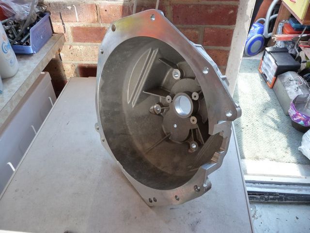
Bellhousing 1
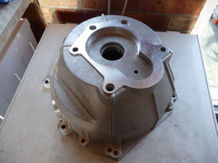

Bellhousing 2
Also taken delivery of the uprated injectors. Decided to fit larger than std ones at this point incase I feel the need to supercharge or tweak more in
the future. They are ford racing injectors, direct swap for std ones. (Bosch EV6 for reference). Rated at 39lb/hr (410cc/min) so double the capacity
iof the std ones.

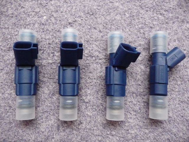
440cc injectors

440cc injector closeup
The cheaper way would have been to use both the std injectors and the bike throttle body ones. But I thought this could look untidy, so decided to
import a new set of injectors from the states. £150 including all the charges was cheaper than getting them over here too!
Next job is get the throttle bodies fitted up and the sump mods completed.
More pics to follow!
coozer - 19/4/09 at 03:30 PM
Love the way your locosting David, what bellhousing is that?
Where did you get the engine and how cheap?
Steve
flak monkey - 19/4/09 at 03:42 PM
Bellhousing a duratec to type 9 one, Titan make them for several people (inc burtons and rally design) as well as RWD motorsport, raceline, dunnell
etc. But they all look like they come from the same pattern to me.
Not sure which one I have as its got no markings on it, dont think it makes aby difference!
The engine cost me £400 plus a trip to birmingham to pick it up. Was told about it by a member on here.
Running total is around £520 including the bellhousing and injector upgrade (sold a few surplus parts)
Not much left to buy other than odds and sods. Am keeping an accurate running total though as I am sure people will be interested.
David
[Edited on 19/4/09 by flak monkey]
rusty nuts - 19/4/09 at 04:35 PM
David, do you need a starter? I have a s/h one you can have for the price of a pint. Can take to Stoneleigh if you want it.
flak monkey - 6/5/09 at 07:36 PM
Big thanks to Mel for the starter at Stoneleigh!  Just needs a clean up.
Sourced a very small brand new denso type alternator from a Honda Prelude for all of £20. Rated at 60amps, which is more than enough!
This will be rigidly mounted to the block right at the bottom on the passenger side. Need to figure out how to wire up the 3 wire regulator though.
Another job for the coming weeks is make the brackets to mount it properly.

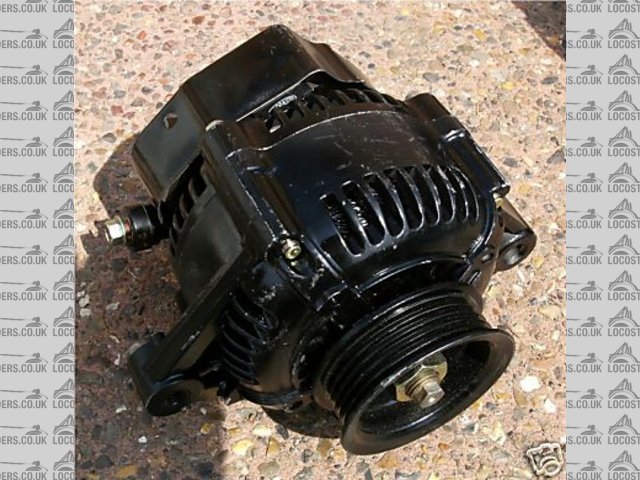
Alternator
Also sussed out how to tension the aux belt which drives the water pump and alternator. The 2006 onward 1.8 duratec ford focus is fitted with a spring
loaded tensioner. This fits where the power steering pump would normally be on the 2.0 engine. Available from Ford for about £70, but also from the
breakers for about £20. The ford part number is 3M5Q-6A228-AD.

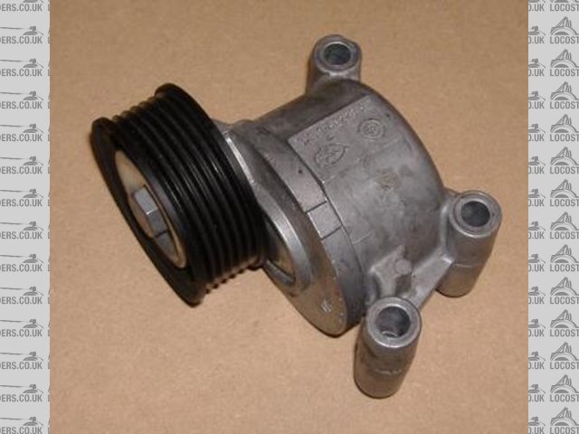
Tensioner
Using the std tensioner is a much simpler and cheaper option than offered by several of the duratec companies...especially if you get one from a
breakers and make the alternator brackets yourself.
David
Jenko - 7/5/09 at 05:04 PM
Great thread, and very interesting.....
Have to ask, are you not worried the injectors will be too big for this engine....I would imaging 250's to be more than enough for duratec on
TB's....I would be concerned that they will deliver too much fuel lower down the rev range (when on minimum duty cycle)....I'm using
gsxr600TB's on a 200bhp engine, and they are fine.
As said, there could be a good reason for going 410cc, so just asking.
Paul.
Staple balls - 7/5/09 at 05:06 PM
quote:
Originally posted by flak monkey
Sourced a very small brand new denso type alternator from a Honda Prelude for all of £20. Rated at 60amps, which is more than enough!
where from?
flak monkey - 7/5/09 at 06:40 PM
quote:
Originally posted by Jenko
Great thread, and very interesting.....
Have to ask, are you not worried the injectors will be too big for this engine....I would imaging 250's to be more than enough for duratec on
TB's....I would be concerned that they will deliver too much fuel lower down the rev range (when on minimum duty cycle)....I'm using
gsxr600TB's on a 200bhp engine, and they are fine.
As said, there could be a good reason for going 410cc, so just asking.
Paul.
Hi Paul,
The reason for going 410cc is twofold.
1. The biggest reason is that I plan to go forced induction in the future and will be looking for 300bhp. This is right on the limit of the capacity
of even the 410cc injectors, so it was a case of futur proofing the engine at this point.
2. You shouldnt really run injectors at 100% capacity. 410cc for 200bhp means 75% duty cycle at max power.
They could indeed cause problems at low rpm but the only way to find out is to try them.
Megasquirt reckons my req fuel will be 8.2 (for 14.7 afr) with that size injector on a 2litre engine, which still seems reasonable.
Like I say time will tell... 
The alternator came of good old ebay. Listed correctly. Most hondas were fitted with very small denso type alternators from the mid 80's
onwards.
David
beaver34 - 7/5/09 at 08:30 PM
what spec engine are you going for, and what power are you looking for? im looking at building a duratech to replace my zetec se engine over winter,
but am wanting to know the limits for pistons rods crank etc...., cheers al
flak monkey - 7/5/09 at 09:01 PM
quote:
Originally posted by beaver34
what spec engine are you going for, and what power are you looking for? im looking at building a duratech to replace my zetec se engine over winter,
but am wanting to know the limits for pistons rods crank etc...., cheers al
I am simply going for a 200bhp spec engine. Std internals on throttle bodies. Realistically though if I see 170-180bhp from the budget option I will
be more than happy. After its all fitted and I have had time to save up some more cash then forced induction will be on the cards.
The limit for std rods and pistons is about 230-250bhp. For anything other than the std cams you need pocketed pistons, though the std ones can be
machined cheaply. This should see 230bhp.
After this you need to really start raising the rev limiter to unlock the power and the std rods and pistons arent really up to anything over 7000rpm.
Forged rods and pistons are readily available, but as always you are looking at about £800 for the set. Add a set of cams, followers and springs and
you are soon into the £1500 bracket for that extra 50bhp, so personally I would rather spend that money on a homebrew supercharger system...
There are some good articles on the SBDev site about what mods will give what power outputs.
beaver34 - 7/5/09 at 09:18 PM
quote:
Originally posted by flak monkey
quote:
Originally posted by beaver34
what spec engine are you going for, and what power are you looking for? im looking at building a duratech to replace my zetec se engine over winter,
but am wanting to know the limits for pistons rods crank etc...., cheers al
I am simply going for a 200bhp spec engine. Std internals on throttle bodies. Realistically though if I see 170-180bhp from the budget option I will
be more than happy. After its all fitted and I have had time to save up some more cash then forced induction will be on the cards.
The limit for std rods and pistons is about 230-250bhp. For anything other than the std cams you need pocketed pistons, though the std ones can be
machined cheaply. This should see 230bhp.
After this you need to really start raising the rev limiter to unlock the power and the std rods and pistons arent really up to anything over 7000rpm.
Forged rods and pistons are readily available, but as always you are looking at about £800 for the set. Add a set of cams, followers and springs and
you are soon into the £1500 bracket for that extra 50bhp, so personally I would rather spend that money on a homebrew supercharger system...
There are some good articles on the SBDev site about what mods will give what power outputs.
thanks, just been on there website, i dont want F/I really, the parts are cheap enough, there are some rods from america for £250, but god knows how
good they are
flak monkey - 11/5/09 at 09:19 PM
Slight change of plan with the sump. Although the std transit sump is level with the bottom of the std bellhousing, the rwd bellhousings are 27mm
shorter allowing more ground clearance with a shortened sump. So its been a case of back to the drawing board (literally) so....
I have been working on a cad model for a new sump this evening. Loosely based on the one CairB made for his duratec, but with a few tweaks.
I am planning on getting all of the parts laser cut and then getting a friend to TIG weld it all together for me. This will hopefully be available as
a kit of parts in the future as well for others who want to install the duratec engine (also be an inlet manifold plate available) if all goes to
plan. This hasnt been finalised yet I hasten to add!
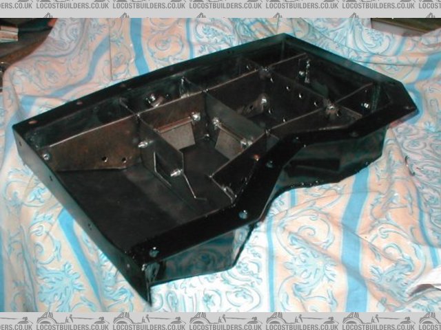
The large square holes will have a flap fitted to allow oil into the pickup area but not out of it. The baffles all have 1/2" rad cut outs in the
corners and the rearmost one one in the middle too. I may add more holes part way up the baffles? Top plate is 5mm, all others are 1.6mm.
Anyone see any major problems? Or indeed have any suggestions for improvement? I am not sure if the rear most baffle is of any use? Would it be worth
moving the middle one back slightly and doing away with the back one?
I havent quite finished it yet, as I want to incorporate a plate which also bolts to the bellhousing to make use of the bolt holes and to simply cover
the bottom of the bellhousing neatly. If I can work out a way of making it strong enough then it will be strutural too. I also need to put the holes
in where the front cover bolts on too.
[see below for pics]
[Edited on 19/5/09 by flak monkey]
Tim 45 - 12/5/09 at 09:43 PM
Looking good David!
Out of curiosity what changes have you made to the CairB sump?
Based on:

DuratecSumpInside
I'd have said they were pretty much the same??
[Edited on 12/5/09 by Tim 45]
[Edited on 12/5/09 by Tim 45]
flak monkey - 14/5/09 at 06:26 AM
quote:
Originally posted by Tim 45
Looking good David!
Out of curiosity what changes have you made to the CairB sump?
I have updated the design pics above now.
To be honest there doesnt appear to be much difference, I have tweaked a few things mainly because I am getting the parts laser cut, which opens up a
few more possibilities more easily. The last remaining jobs are to decide where to put the dipstick and drain plug and to design in a few features to
make it more simple to assemble.
I have now added in another flap valve in the rear most baffle to allow oil to flow forward more quickly under braking. I have also revised some of
the baffles slightly.
The top and front flanges are thicker (5mm) as well, allowing them to be ground flat after welding them up, as I have the equipment to do so, meaning
less sealer will be neaed to get the sump to seal (there's no sump gasket on the duratec).
I have also added in the windage tray, which is going to get a few more mods to prevent oil climbing the side of the sump under hard cornering.
Talking to CairB he hasnt had any issues with his design on trackdays or the road so its perfectly good as it is. What I am trying to do is develop
the design a little more.
Like I said in the original post, all the parts for mine will be laser cut, and a kit of parts will be available for others thinking of installing the
Duratec too. I will post more details of this as things progress.
Cheers,
David
flak monkey - 19/5/09 at 04:14 PM
Sump design now complete and will shortly be sent off for laser cutting!



Fingers crossed it all fits together! 
Adam R. - 24/5/09 at 07:32 PM
i`m building also with duratec but with mx5 gearbox
and I have idea, if duratec block are the same as 2.0 mazda mx5 `05 and up so we can use stock mx5 oil pan 
flak monkey - 24/5/09 at 07:53 PM
quote:
Originally posted by Adam R.
i`m building also with duratec but with mx5 gearbox
and I have idea, if duratec block are the same as 2.0 mazda mx5 `05 and up so we can use stock mx5 oil pan 
Possibly, if the bellhousing is level with the bottom of the sump.
With the aluminium bellhousing for the type9 box it is designed to give more ground clearance, meaning you can make the sump about a 25mm shorter.
David
flak monkey - 7/6/09 at 02:05 PM
Today I have been working on getting the alternator fitted up (amongst other things!  )
)
Mounts fabricated from 5mm steel, they need a bit of trimming up then painting and fitting permanently. I might drill some lightening holes in the
lower mount too.
They position the alternator within about 3mm of the block.
Total cost for alternator and mounts was £20, which I think you will agree is better than over £300....

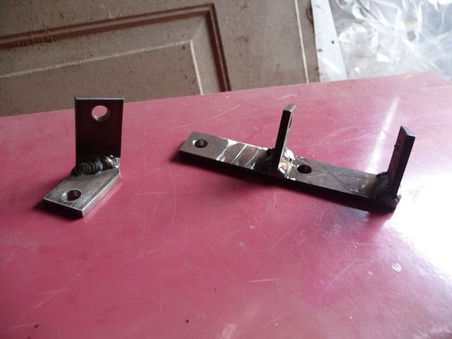
Alternator mounts

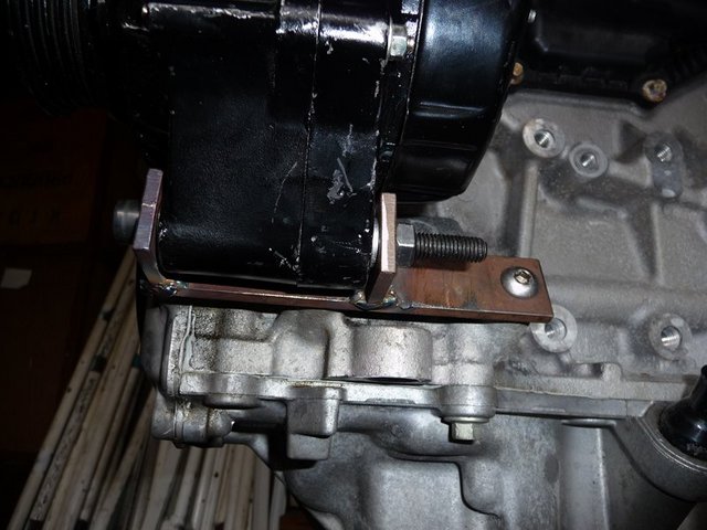
Alternator mounts

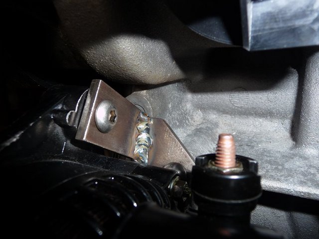
Alternator mounts

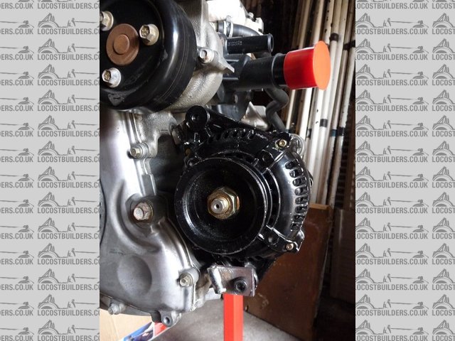
Alternator fitted
The next jobs are to get the new fuel rail milled (job for work this week) and hopefull I will be welding up the sump next weekend if all goes to
plan!
On the sump front, kits to build your own sump will be available to weld up yourself for the princely sum of ~£70+P&P. Obviously mine is the
prototype, so there may be some design tweaks before they go on sale, but they will be available very soon 
David
[Edited on 7/6/09 by flak monkey]
goaty - 7/6/09 at 02:41 PM
i would def be interested in a sump kit 
flak monkey - 7/6/09 at 02:45 PM
I'll post more about them when everything is finalised 
flak monkey - 12/6/09 at 07:29 PM
Finished the alternator brackets off today and fitted them up finally

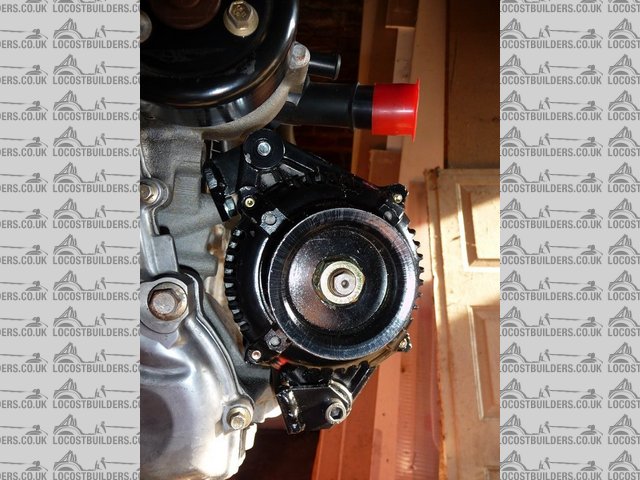
Alternator mounts finished

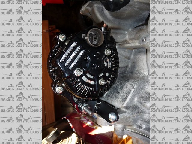
Alternator mounts finished
will measure up for the belt tomorrow.
Unfortunately the laser cutting has been delayed so won't be welding the sump up tomorrow 
Will pobably spend the time stripping one of my diffs and driveshafts down instead.
David
Benzine - 12/6/09 at 08:31 PM
Looks good! How did you go about alligning the pulleys? Straight edge + lots of measuring? frickin' lasers? It's something I'll have to
do soon so I'm curious ^_^
flak monkey - 12/6/09 at 08:46 PM
The pulleys were aligned using a piece of box section held on the crank pulley by my able assitant while I marked out the alternator brackets and then
tacked them together. Got it right within about 0.25mm which is good enough.
Took a bit of fiddling but got it right in the end.
The measurement from the front of the pulleys to the root of the first vee was the same on both which made the alignment much simpler.
Benzine - 12/6/09 at 09:25 PM
Cool thanks, my crank pulley has a big lip around it so I'll be able to clamp some box section on to it 
mangogrooveworkshop - 21/6/09 at 12:12 PM
http://k80rum.co.uk/default.aspx
super charger upgrade?
flak monkey - 21/6/09 at 02:25 PM
quote:
Originally posted by mangogrooveworkshop
http://k80rum.co.uk/default.aspx
super charger upgrade?
Aye, seen that and plan to make that leap next winter if funds allow.
flak monkey - 21/6/09 at 02:52 PM
The parts for the sump arrived on Friday morning, which has meant that inbetween visiting Newark yesterday and all the other usual weekend stuff I
have managed to make a start on getting it welded together.
Check fitted the flanges on friday and all seem to line up well, which was a great relief!
Also spent friday afternoon making all the flap valves and welding them all in (they can be seen in the pics below) and getting them all to operate
smootly.
A slight modification is required to a couple of the baffle lengths and the two sides (a little too generous with the bend allowances, but this will
be rectified in the design now)
Screwed the flange down to a nice thick bit of block board and welded on the end plate which bolts to the front cover of the engine.
The sides were then bent by clamping down to a bench, sandwiched between 2 bits of wood. Allowed for nice clean bends. And I was quite chuffed with
the result considering I was too impatient to wait until tomorrow to bend them on the machine at work tomorrow!

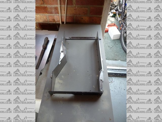
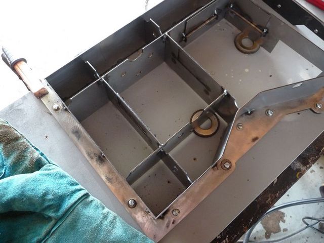
Sump build
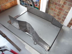

Sump build 3
After that the sides were tacked into position, and then the back followed. Nice and easy so far. And having everything laser cut was a joy as it
meant everything fitted together just as expected.

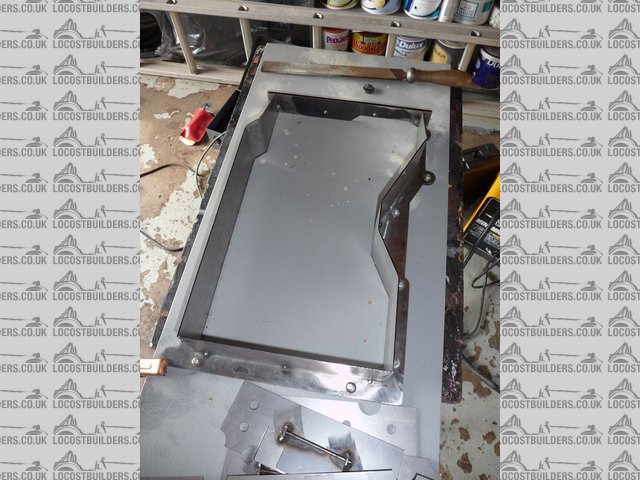
Sump build 2

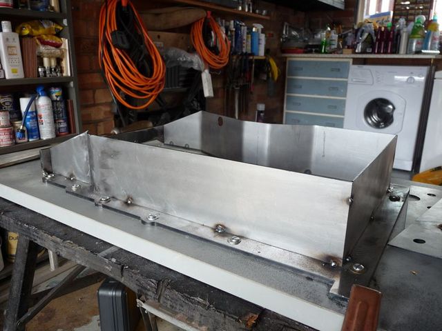
Sump build 4
The next step was to weld in the baffles. As I mentioned above I had already spent friday fixing in the flap valve parts. The rest is quite easy as I
had slots cut in the baffles so they literally slot together.

Sump build 5

Sump build 6
The next job is to bend the bottom plate to fit and to decide where the dipstick is going to be fitted so I can drill the hole in the side of the sump
for it. I think this will end up toward the back of the sump, and I will be retaining the std mondeo dipstick and tube.
Drain plug fits in the hole in the side which you can see in the pics. Need an M14 nut with one side ground down to suit then a std pinto drain plug
and sealing washer can be used.
All in all its going quite well....I think.....
David
goaty - 21/6/09 at 03:11 PM
quote:
Originally posted by mangogrooveworkshop
http://k80rum.co.uk/default.aspx
super charger upgrade?
That is the perfect link, exactly what i am building at the mo, very helpful thank you.
flak monkey - 25/6/09 at 05:30 PM
More progress on the sump construction.
Everything other than the bottom is tacked on now. There is still the windage tray fitting to work out as well.
May have got a bit carried away with shortening the pickup pipe though, what do you think? The pipe angle is the same as the mondeo std i.e the end is
angled to the bottom of the sump. The closest end is within 5mm of the bottom and the other end is 9mm away. Too far or will it be ok?
It will be submerged in a total of 70mm of oil when the oil level is at max.

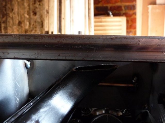
Sump build 7

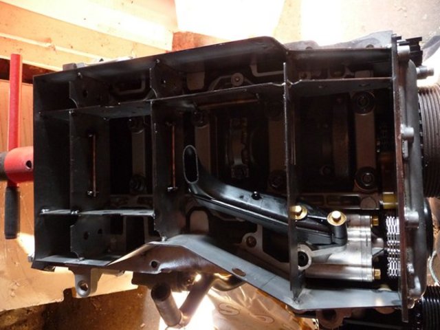
Sump build 8

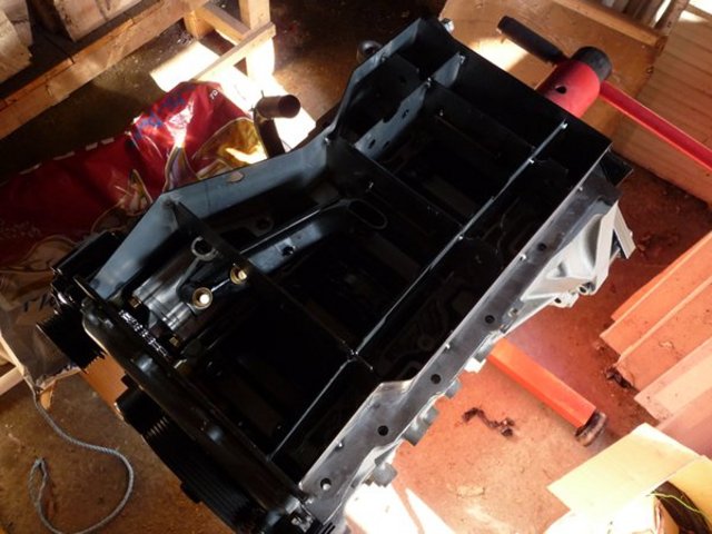
Sump build 9
Stuart_B - 25/6/09 at 07:28 PM
this is a good progress, so doe sthe engine need to be moved back 3inchs?
just as me and my dad want to convert my kit car from a 1.6 pinto to a 2.0duratec engine during the winter.
as well the sump desing, i would love to beable to do that on a coumputer.lol so if i did do the conversion at the moment it is just talk between me
and dad, and mum saying, maybe.lol would i you send me the drawing so i can get it made?
as well does the exhaust ports look simlar to a pinto one?
and could i get bike carbs running mejafolt instead of throttle boddies and megasquirt?
sorry for all the questions david.
thanks
stuart
flak monkey - 25/6/09 at 07:39 PM
Hi Stuart,
Engine doesnt need to be moved back, but its worth it if you can. The reason you can is that you need to use a hydraulic clutch which means there is
no release arm to fit into the transmission tunnel.
The sump will be available as a kit from 3GE components soon. I just need to finish my prototype off and tweak a couple of bits on the design.
Pinto exhaust can be modded to fit the duratec yes. Port spacing very similar.
You could run it on bike carbs, but I wouldnt expect to see the power you can get from a big set of inection throttle bodies. SBD got 175bhp on 48DCOE
carbs and 198bhp on 48mm throttle bodies.
David
PS havent you added me on MSN?
Stuart_B - 25/6/09 at 07:54 PM
hi david, thanks for the info, so woth geeting bike throttle bodies then, with those figures, how hard is it to set up, as i am not very good, manily
never done any of that before.lol
yes edd, gave me you msn, just aint on it anit the moment, so throught i would ask on here.
i will pseak to you soon on msn, more stupid questions.lol
thanks
stuart
flak monkey - 28/6/09 at 02:19 PM
More sump progress and piccies.
Also decided to get another pick up pipe and have cut it so its parallel with the bottom of the sump, and 5mm clear.
Final job before getting it all TIG'd up is to decide on the position of the dipstick and get the tube welded on. Think its going to go exhaust
side as there is less in the way! 


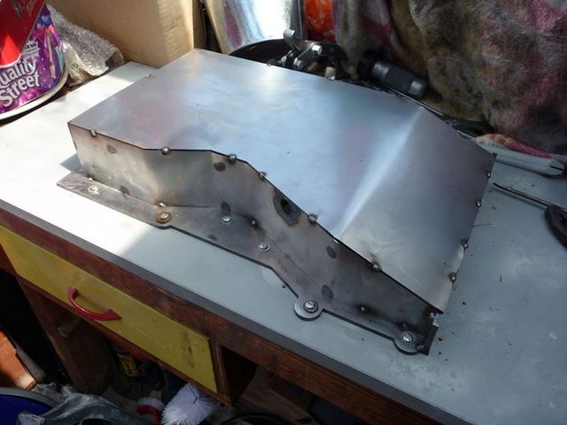
Sump build 11

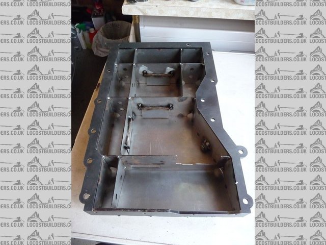
Sump build 12
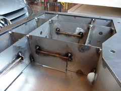

Sump build 13

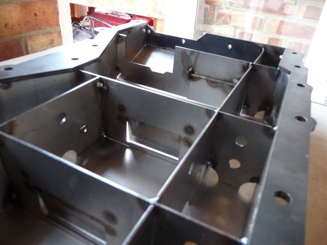
Sump build 14
Also finished off the fuel rail, all bar some spacers for the bolts which I'll make this week. And test fitted the laser cut inlet manifold
flange which fits beautifully. I designed it so I could cut away the small lips on the bottom of the inlet ports on the head. What looks like a lip in
the pics is'nt its just where the ali is shiney where I filed it away.

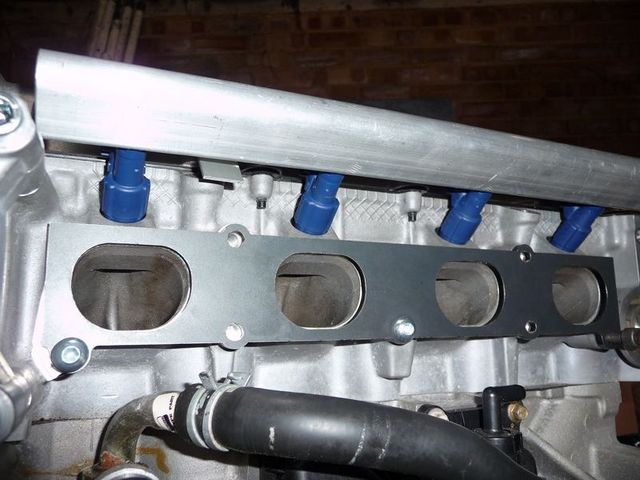
Inlet manifold plate test fit
The tube has arrived for the manifold too. Was a bit tricky to find (48mm OD (1 7/8" ) but got some in the end. Three of the inlet tracts will be
straight (cyls 2-4) and cyl 1 will have a slight angle as the TPS sensor interfered with the belt tensioner otherwise. The trickiest bits going to be
making the angled runner nice and smooth and belend into the odd shaped inlet ports.
Oh well, another challenge which I am sure can be overcome....
David
Stuart_B - 28/6/09 at 05:07 PM
that is looking good, so in the sump, are thoses flaps to let oil float freely around, then stop it lossing oil in hard turns?
stuart
flak monkey - 28/6/09 at 05:29 PM
The idea of the flaps is to allow oil to flow around freely under normal circumstances and then under hard acceleration/braking/cornering they will
retain the oil in the pick up area.
There are small notches in the baffles too to allow oil to flow around slowly too.
There is also a windage tray to stop oil sloshing up the sides of the block in the corners.
Basically its all about slowing the surge of oil down but it still needs to flow around under normal circumstances.
goaty - 23/7/09 at 07:48 PM
hey flak,
any news on the sump progress??

flak monkey - 23/7/09 at 07:54 PM
Yeah, it all fits, just waiting for it to be finish welded by a friend who'll make a better job of it than me.
Will get the finished laser cutting drawings off to the cutters this week too. A few slight tweaks were needed, but nothing major!
Not been able to get in the garage for a while, been busy with other things unfortunately.
David
goaty - 24/7/09 at 05:53 PM
cool, is it ali or steel??
cant wait to see it done, am hoping to get one for mine too 
flak monkey - 24/7/09 at 07:56 PM
quote:
Originally posted by goaty
cool, is it ali or steel??
cant wait to see it done, am hoping to get one for mine too 
It is steel, but there is no reason you couldnt have one cut in ali, would have to get a price for it though.
Only reason I did it in steel is I dont have access to aluminium welding equipment 
beaver34 - 30/7/09 at 09:02 PM
hows it coming along?, im starting mine this month, hopefully picking a head up this weekend
flak monkey - 30/7/09 at 09:23 PM
Slowly. Run out of time and money at the moment.
Sump is away being welded up by my mate.
Inlet manifold will be made next week as I am on holiday from work.
Also will be making a billet ali water pump pulley, just because I can really.... 
David
flak monkey - 17/8/09 at 07:38 PM
Righto, back on the case, and things need to start moving.
Here are the fruits of tonights labours. From 5pm to now has made me this:

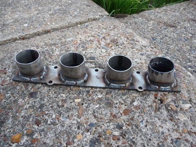
Inlet manifold 1

Inlet manifold 2

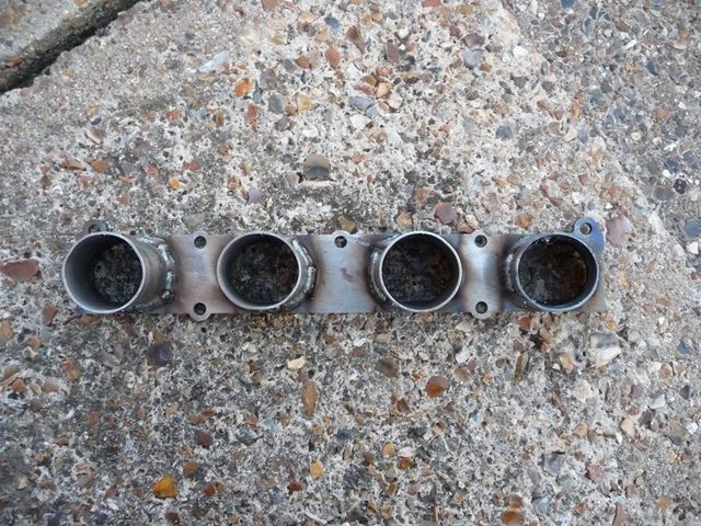
Inlet manifold 3

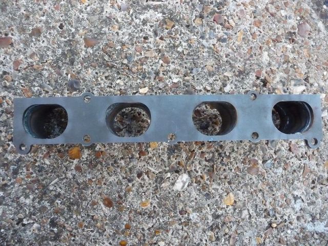
Inlet manifold 4
Sadly due to the position of the aux belt tensioner the runner for the fist throttle body can't be dead straight.
I havent trimmed it up inside yet either as it was still smoking when I took the pics. However its distroted more than I had hoped so need to try and
straighten that out somehow. Any ideas?
I should also point out, although the tops of the tubes are a bit wobbly at the moment its going on the mill at work tomorrow to have them all skimmed
nice and flat 
David
[Edited on 17/8/09 by flak monkey]
Stuart_B - 22/8/09 at 03:49 PM
hi david, glad to see it is coming along, i am looking at soem engines at the moment, have you got teh 145hp one or the 170hp one?
do you now what i would have to change to get to 170hp?
as well what throttle boddies are you using?
i was think a set of 1000cc bike throttle boddies.
cheers
stuart
flak monkey - 22/8/09 at 04:24 PM
The ST170 engine is NOT a duratec engine. Its a zetec with VVT which needs to be controlled by the ECU. It just has a duratec badge, other than that
its all zetec.
Mine is a 150bhp one from mondeo/st150 etc etc.
The throttle odies are GSXR750 which are 42mm, exactly the same size as GSXR1000 but you usually pay less for the 750s 
flak monkey - 23/8/09 at 02:25 PM
Took the pinto out yesterday and it was collected in the afternoon, so all in a good days work so to speak! No major hiccups other than throwing
gearbox oil everywhere! Forgot about it pouring out of the prop end! 
Also finished off my shiney new ali water pump pulley this morning. Slightly underdrive (about 5%) compared to the old one. But also about half the
weight, and I reckon it will look nicer too 

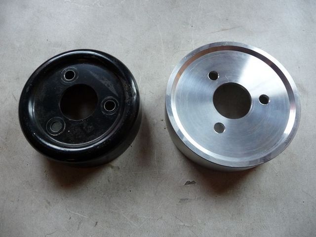
Water pump pulley 3

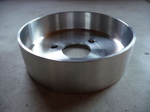
Water pump pulley 2
Also just finished fettling the inlet manifold. Just need to get it skimmed front and back to completely finish it off.
David
flak monkey - 24/8/09 at 07:29 PM
Fitted all the blanking plugs to the throttle bodies so they are now ready to fit.
I am as of yet undecided whether to machine off the old injector fixings. I might leave them as they could come in handy for fixing things too.

What I need to do now is work out how to make a positive retainer to hold the throttle bodies to the manifold. I really dont want them dropping off,
or indeed blowing off when the supercharger is fitted.... 
Stuart_B - 25/8/09 at 05:54 PM
that pulley looks nice.
where baouts did you get the bellhousing from, or ehich search words should i use to look on ebay?
i have my duartec engine now
flak monkey - 25/8/09 at 06:02 PM
The bellhousing came off ebay. I paid £120 for it. They do come up every now and again. Sometimes listed under mk2 escort parts.
I assume you got a HE duratec and not a zetec duratec? lol
Stuart_B - 25/8/09 at 06:27 PM
yep a he 2.0 duartec engine, mine cost £205.
i need a starter and a flywheel, i read on your website a 1.8 flywheel, what size stater or are they the same?
stuart
flak monkey - 25/8/09 at 06:57 PM
Starters are the same. Some 1.8s still have a dual mass flywheel.
I'll have a look at mine and get the part number off it, if you then go into a ford dealer they will be able to tell you what models it was
fitted to exactly.
David
beaver34 - 25/8/09 at 09:29 PM
if you need any ford parts info drop me a u2u, its all i do all day 
flak monkey - 26/8/09 at 09:21 PM
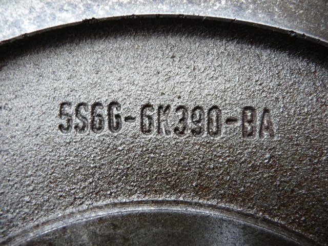
Flywheel part number

Rescued attachment m_P1000390.jpg
flak monkey - 27/8/09 at 07:07 PM
This is the water pump pulley fitted

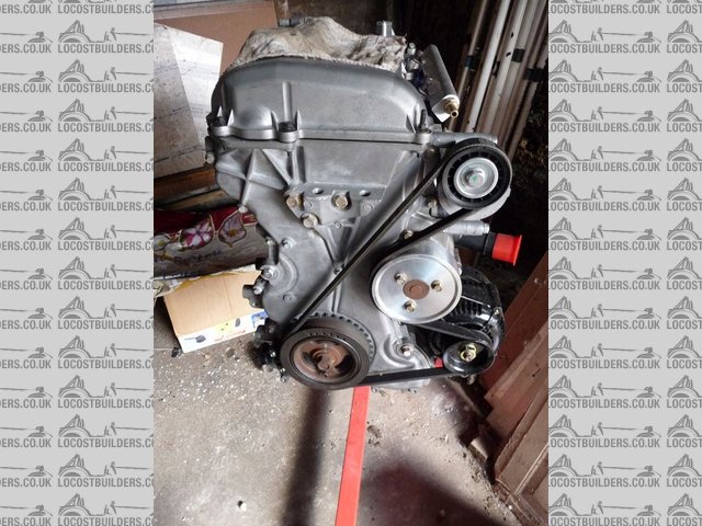
New water pump pulley fitted
goaty - 30/8/09 at 08:45 AM
has anyone heard anything about oil pump failures on duratecs??
I got told about two yesterday and am now wondering which would be the best route, or just uprate the pump....
Dont think there would be much room for a dry sump set up.....
flak monkey - 6/9/09 at 08:24 AM
quote:
Originally posted by goaty
has anyone heard anything about oil pump failures on duratecs??
I got told about two yesterday and am now wondering which would be the best route, or just uprate the pump....
Dont think there would be much room for a dry sump set up.....
Not heard specifically of oil ump failures. But sadly I dont think anyone is making an uprated aftermarket pump yet, seems drysump kits have taken
over.
Like you I dont have room for all the dry sump gubbins. Having said that, someone (maybe cosworth) make a drysump for the duratec where the scavenge
pump is in the actual sump pan rather than a seperate bit which you need to find a home for. May be more suitable for a locost install?
goaty - 6/9/09 at 06:53 PM
possible, i have just picked my Titan one up but i think iwill be able to squeeze it all in. Tank is the main issue i think.
Luckily the bloke i bought it off works for Caterham developments team and this is the same things he does. Bought an ap friction plate for £40 too.
But he said get in touch whenever for help as they just made one and got 330bhp.
So it can fit and shoudl go well 
Will be interesting to see how the different builds turn out....cant wait.
all the best
ps, he said that they haven't had any oil pump failures as yet though.
Breaker - 6/9/09 at 08:52 PM
quote:
Originally posted by flak monkey
This is the water pump pulley fitted


New water pump pulley fitted
Any particular reason you want the water pump to run slower (larger pulley) ?
BTW: Duratecs with aircon have a double crankshaft pulley. 1pulley for the water pump and alternator and the other pulley for the aircon. Perhaps you
can use the second one for your supercharger ?
[Edited on 6/9/09 by Breaker]
flak monkey - 7/9/09 at 07:02 AM
quote:
Originally posted by Breaker
Any particular reason you want the water pump to run slower (larger pulley) ?
BTW: Duratecs with aircon have a double crankshaft pulley. 1pulley for the water pump and alternator and the other pulley for the aircon. Perhaps you
can use the second one for your supercharger ?
Thanks for that, I knew some had a double pulley but wasnt sure which it was. I would like to retain the single pulley if poss though.
The thoughs behind running the pump slower? Not much really other than upping the red line a bit and by increasing the pulley diameter a bit will stop
it going over its design speed. Will have to see what effect it has on cooling at lower speed. If I run into problems, then I may end up fitting an
electric water pump anyway.
David
FASTdan - 7/9/09 at 02:11 PM
what are you doing in terms of the oil filter? I've seen stuff about replacing the standard housing with an aftermarket one to fit a traditional
filter that sticks off the block sideways - presumably to eliminate ground clearance issues? I've not assembled ours yet to see how low the
standard housing hangs.
Did you look at using the RWD sump (ranger) at all? just wondering what thats like in terms of ground clearance etc as thats what we have. We were
planning to baffle that sump.
you may have mentioned it somewhere and I've missed it so apologies if thats the case.
flak monkey - 7/9/09 at 02:19 PM
quote:
Originally posted by FASTdan
what are you doing in terms of the oil filter? I've seen stuff about replacing the standard housing with an aftermarket one to fit a traditional
filter that sticks off the block sideways - presumably to eliminate ground clearance issues? I've not assembled ours yet to see how low the
standard housing hangs.
Did you look at using the RWD sump (ranger) at all? just wondering what thats like in terms of ground clearance etc as thats what we have. We were
planning to baffle that sump.
you may have mentioned it somewhere and I've missed it so apologies if thats the case.
The ranger sump is very deep, I did have one but it required so much chopping about I decided to make my own. My sump design is only 75mm deep in
total and this is the total depth you have available to make the sump level with the bottom of the after market bellhousings.
WRT the oil filter. I am as of yet undecided. I have a take off block for a remote filter (basically a milled aluminium block) which I may use. Or I
might splash out on a proper block from raceline to mount the filter on the side of the engine. This will basically all come down to the amount of
space I have next to the engine.
I do know the std filter will hang way too low.
David
FASTdan - 7/9/09 at 03:30 PM
quote:
Originally posted by flak monkey
My sump design is only 75mm deep in total and this is the total depth you have available to make the sump level with the bottom of the after market
bellhousings.
David
how does the height of the aftermarket bellhousing compare to the standard pinto one?
flak monkey - 11/9/09 at 04:20 PM
Tried the supercharger up to the block the other day.
Looks like it will fit nicely, still may need to move the steering column though.


goaty - 11/9/09 at 04:22 PM
looking very good, can you get to the oil lines ok?? what about running the air hoses from it??
flak monkey - 11/9/09 at 04:27 PM
quote:
Originally posted by goaty
looking very good, can you get to the oil lines ok?? what about running the air hoses from it??
Yeah the oil hoses are on banjo fittings so can be close to the body.
Oulet hose might be an issue. But until I get it in the car I wont really know 
All I do know is that to the edge of the supercharger outlet (which needs turning around) is 2" less than to the edge of the alternator on the
other side of the engine bay.
I will be keeping it all as close to the block as poss to avoid any potential issues with hoses.
Micael - 11/9/09 at 07:23 PM
I plan to go the duratec route (swaping from Zetec)and this thread is very informative.
I wonder about one thing.
Where is the trigger pickup located? Does the Duratec use the same principle as the zetec, ie flywheel.
flak monkey - 11/9/09 at 07:25 PM
quote:
Originally posted by Micael
I plan to go the duratec route (swaping from Zetec)and this thread is very informative.
I wonder about one thing.
Where is the trigger pickup located? Does the Duratec use the same principle as the zetec, ie flywheel.
You can see it on the pic above. The trigger wheel is on the crank pulley and the sensor is in the approx 8 0'clock position.
Micael - 11/9/09 at 08:11 PM
how could i missed that.

flak monkey - 18/9/09 at 04:55 PM
After alot of head scratching I think I have now come up with the right recipe for duratec flywheel/clutch on the cheap.
The flywheel part number is:
5S6G-6K390-BA
And it is fitted as std to the 2.0 Focus and 2.0 Fiesta ST. Available new from ford - not sure on the price though. Or there should be a few kicking
around second hand. St150 fiestas seem to end up in the breakers quite often!
These flywheels are ~5mm smaller than the mondeo dual mass flywheel, so make sure you get the starter from an ST or Focus too.
For standard power (200bhp or so) the standard cover plate with a mondeo zetec friction plate will suffice. This is the same clutch kit as used on the
rwd zetec conversions. Usually retail for about £30. This set up can use the standard ford release cylinder (CSC002) which will bolt straight into the
bellhousing but may need a small spacer which are available off the shelf.
The other aftermarket clutches are only rated to around 250bhp, after this you are usually told you need a 7.25" race clutch and flywheel. Which
is mega money.
For big power (upto 350bhp) a heavy duty AP Racing clutch plate can be fitted from an XR3/Rs Turbo. The AP part number is CP3560-2. A compatable
friction plate is any of the 215mm friction plates which are made for the pinto engine. So you have a choice of cerametallic or organic. Eg CP5352-5
or CP5354-38. I have spoken to AP about this and they dont actually make any 220mm friction plates, for their 220mm covers, they are all supplied with
215mm ones.
The release cylinder/bearing to suit the HD option is one from a Saab 99/900/9000 with a round nose release bearing. It will need an approx 5mm
adaptor/spacer making to fit it to the bellhousing. Which I will be able to supply.
It will also require the central hole in the pressure plate opening out by ~2mm, this can be done with a die grinder/dremel. Or I can machine the
material out, but will require the whole flywheel/clutch assembly to do this.
Hope that helps, and clarifies a few points as well!
David
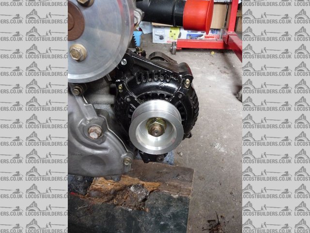
flak monkey - 19/9/09 at 10:09 AM
Ali alternator pulley made and fitted yesterday. Needed to make it slightly smaller to keep the speed of the alternator up with the reduced dia crank
pulley.

Ali alternator pulley 1

Ali alternator pulley 2
Mounted the flywheel and clutch up in the lathe and skimmed out the bore of the pressure plate. Actually turned OK with a CBN tip 

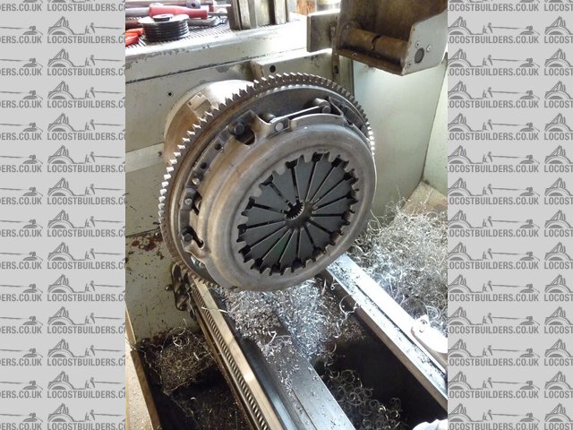
Clutch skim
And got the starter motor modifed, now engages perfectly (or seems to at least) with the fiesta flywheel. All that was required was 2mm skimmed off
the mounting face.

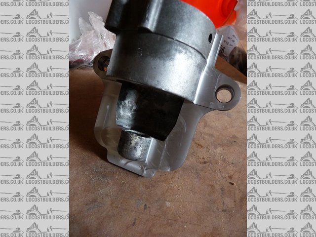
Starter mod
I am now in the middle of removing all the front suspension ready for a paint up!
Micael - 19/9/09 at 06:24 PM
Thanks for the info!
I'm of to the scrap yard in search of a fly wheel.
matt.c - 19/9/09 at 07:18 PM
You have been busy aint you!!!! 


Looks really good so far mate. Glad to see you are putting the welder to good uses. 
mconley3 - 1/10/09 at 11:14 AM
Is there are part number for a normal intake gasket on the Duratec? I've been unable to find a reference and was planning on trying to make one
from gasket material.
Thanks,
Mark
flak monkey - 1/10/09 at 11:21 AM
There isnt one as the std intake has 4 moulded o-rings to seal it. The aftermarket cast manifolds use these too.
Like you I will be making one from gasket material.
David
flak monkey - 1/10/09 at 04:07 PM
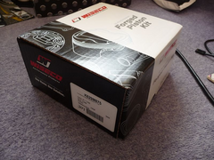
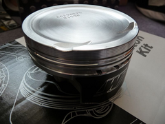
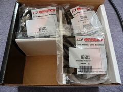
Forged pistons arrived from the staes today. Not bad, 4 working days shipping and not bad on import duty either.
Made in the USA, complete with rings, pins and locks worked out at about £315 for the set.
10:1 compression ratio, so slightly lower than the standard 10.8:1 but near enough for me.

Forged pistons

Forged pistons

Forged pistons
Also imported a couple of set of bearings, which also worked out rediculously cheap! 
Still waiting for my forged rods though, now a month since I ordered  must be on a slow boat from somewhere

Stuart_B - 2/10/09 at 04:48 PM
nice bit of kit.
i have mine on an engien stand now, cleaning it, and make the blanking plate for the erg port this weekend, and hopefuly getting soem throttle boddies
soon.
stuart
flak monkey - 12/10/09 at 03:17 PM
Things are going rather slowly at the moment as I have spent the past 3 weeks working on getting my new garage in a habitable state which has involved
some major works! I now have a dust and draught free garage though, 4.5x4.5m so a much better work space.
Sadly I need to get the suspension and wheels back on the chassis so I can get the car on a trailer and over to its new home!
Also majorly let down by one supplier in the US, now in the process of claiming my money back through paypal as they arent responding to my emails and
I ordered over 6 weeks ago. Fingers crossed paypal will actually refind my money so I can source another set of rods from a company I now trust!
Next month I hope to source the intercooler, I will then have all the major parts to get the engine fitted. So by the end of Nov I hope to have engine
and transmission sorted 
goaty - 12/10/09 at 06:54 PM
all sounding very good, shame about the us company, thats the main reason i try not to use us unless really need too. Paypal are normally good at this
though  .
.
I would be interested in one fo the intercoolers too if poss please 


cheers
joe
flak monkey - 12/10/09 at 09:32 PM
I will be sourcing from GRS for the intercooler. Will ask if he is able to do any discount for 2 off.
Should be able to make it fit any seven rep, bt will depend on position of body and rad to some extent. Nothing a bit of juggling should fix though 
radom - 14/10/09 at 01:12 PM
how much does this flywheel weight?
flak monkey - 14/10/09 at 01:46 PM
quote:
Originally posted by radom
how much does this flywheel weight?
Not weighed it, estimate around 6.5kg which is a darn sight lighter than the 11kg dual mass lump!
JAMSTER - 16/10/09 at 06:00 PM
can i buy a sump/sump kit yet if so how much thanks
flak monkey - 28/10/09 at 05:21 PM
The last of the parts from the States arrived today.
Forged rods and ARP head stud kit. Worked out around £400 inc delivery.
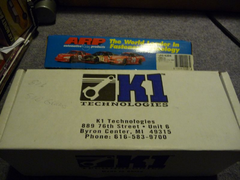

Rods and bolts

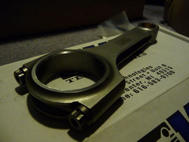
K1 Rod
Rods were supplied complete with ARP bolts included in the price. Machined all over and shot peened made from forged billet. Certainly look the part
anyway.
The engine strip down will begin in a couple of weeks once I have finished some DIY on the house 
Stuart_B - 28/10/09 at 06:36 PM
they do look nice.
scootz - 12/11/09 at 01:30 PM
I'm guessing there are different sumps for different Ford Duratec models... ???
The one on my ST150 engine looks like it would be level with the lowest point of the bellhousing!
flak monkey - 12/11/09 at 01:41 PM
quote:
Originally posted by scootz
I'm guessing there are different sumps for different Ford Duratec models... ???
The one on my ST150 engine looks like it would be level with the lowest point of the bellhousing!
They all do, I thought mine, but the after market bellhousings are also shorter than the std one by about 25mm.
If that makes sense!
The aftermarket sumps are 75mm deep from mounting face to the bottom. This makes them the same level as the RWD T9 bellhousing. If your std sump is
any deeper than that then you are sacrificing some ground clearance basically.
David
scootz - 12/11/09 at 06:08 PM
Aaaargh... thought I'd scored by buying an unused and uprated Zetec clutch kit at a bargain price, but it's the wrong size!
It's a 240mm kit and the ST150 engine is a 220mm one!

flak monkey - 12/11/09 at 08:10 PM
You want an uprated RS Turbo clutch (or any other 220mm ford pressure plate) and a HD pinto friction plate 
I assume the ST150 engine had the solid flywheel on then?
David
[Edited on 12/11/09 by flak monkey]
scootz - 12/11/09 at 09:20 PM
It does indeed... I remembered the bit about an up-rated Zetec clutch, but forgot to check if there were different sizes!
DOH!

flak monkey - 14/11/09 at 04:03 PM
Started stripping the Duratec today with the intention of fitting the forged rods and pistons. Started at around 12 and just finished.
Before picture:

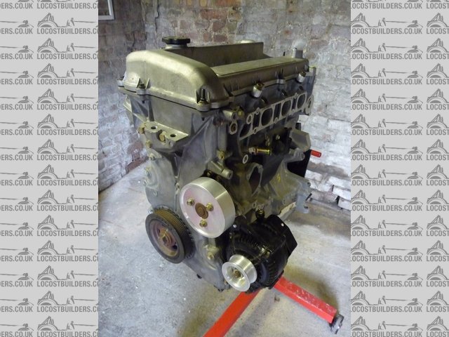
Strip 1
The first thing to do was slacken the crank pulley bolt. Was too much of a problem, sliced up an old pressure plate to lock the crank against the
engine stand and it came undone fairly easily.
Next cam cover came off, had it off when I first got the engine so was painless

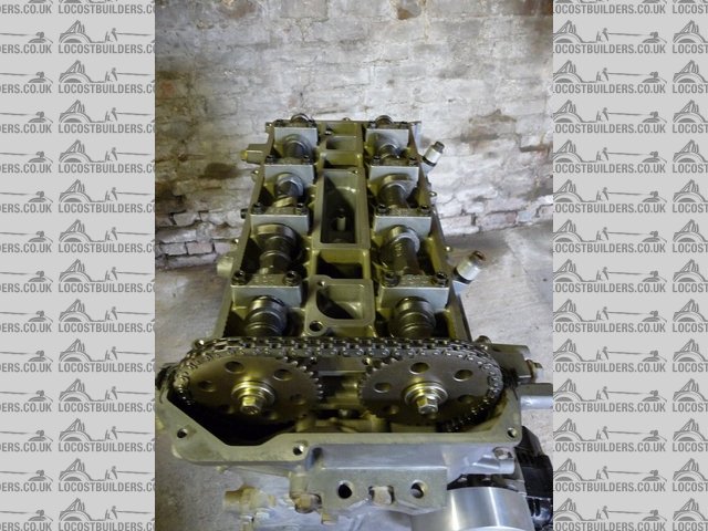
Strip 3
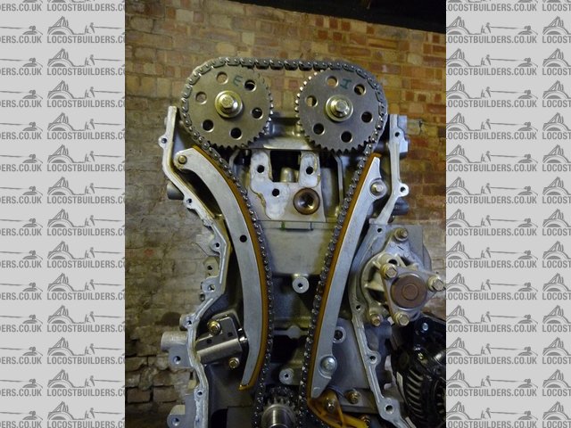
Next removed the front cover, took out all the bolts and gave it a few taps with a hammer to remove it. It was suprisingly clean inside, no signs of
burnt on oil or exessive wear on anything. I have yet to scrape all of the old sealant off the flanges.

Strip 4
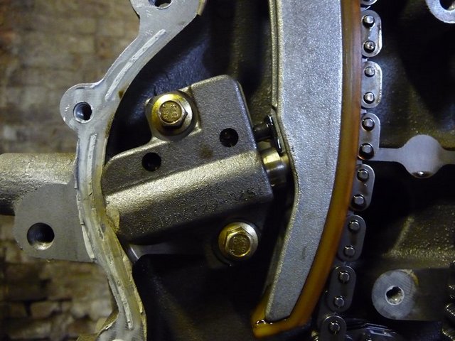
Next step was to remove the cam chain, which means removing the chain tensioner by undoing the two bolts then removing the 2 guides. The chain then
simply lifts off.

Strip 5
Next the cams were removed, taking careful note of the position and orientation of the caps.
Then came the first suprise...the exhaust cam is snapped next to the 3rd cap from the front. Thankfully there doesnt seem to be any damage to the
head, valves or anything other than the cam itself. The break looks clean and it doesnt look like the engine has been run with the cam broken. So just
as well I decided to strip the engine to fit forged parts afterall! Now on the hunt for a std exhaust cam!
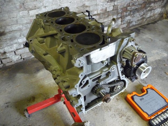
Anyway, head was removed without drama, making sure the bolts were slackened in reverse order.

Strip 6
Next came the conrod bolts. These are torx headed, but male rather than female and need the appropriate socket. Not particularly tight. Again these
were removed and the caps numbered.
The the main bearing ladder bolts are very tight, just need a long breaker bar though.

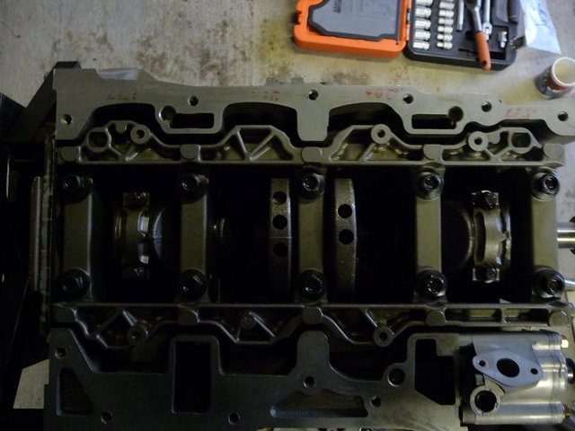
Strip 7
After that the cranks lifted out and the pistons pushed out.
Next job is to take the crank, pulley and timing gear to Scholar to get them keyed.
David
[Edited on 14/11/09 by flak monkey]
Xtreme Kermit - 14/11/09 at 05:27 PM
Looking good!
I remember reading somewhere that the cam chain tensioner can cause issues of duratecs.
Are you planning to replace/upgrade?
flak monkey - 14/11/09 at 05:34 PM
Thanks. 
My understanding was that there have been issues with the tenisioner at prolonged high revs (i.e. race use) but in normal driving and with a 7500rpm
or less rev limit the standard one was ok.
I know SBD do an aftermarket one to fit though.
David
scootz - 17/11/09 at 08:28 PM
What are you guys doing with the plumbing... ???
I had resigned myself to going down the Raceline route, but as I've bags of room in the engine bay I thought I'd just core-plug one of the
ports on the OEM outlet and route piping to the rad. Am I being a tad simplistic, or is it simply a case of 'if the cap fits... '???
flak monkey - 17/11/09 at 08:43 PM
I was going to use some 32mm stainless tube to bring the outlet on the back of the head to the front and then simply connect to the rad.
Its a job for the next month or so.
Should be simple enough to fabricate a pipe to do it rather than spend a fortune on a water rail
David
scootz - 17/11/09 at 08:55 PM
I'm trying to visualize the OE outlet... am I right in thinking it has 2 large diameter opposing outlets and one smaller one???
flak monkey - 17/11/09 at 08:59 PM
It has 4 connections IIRC 32mm, 2 off 19mm and a 6mm IIRC.
So 32mm to rad, 19mm to header tank, other to thermostat bypass and 6mm air bleed to header.
David
scootz - 17/11/09 at 09:19 PM
Cheers David.
flak monkey - 21/11/09 at 06:23 PM
Continued with the engine rebuild today.
Deglazed the bores and then washed everything down to get rid of the grit.
Fitted the ARP main studs into the block. Removed, inspected and cleaned the bearings in both the block and the ladder.
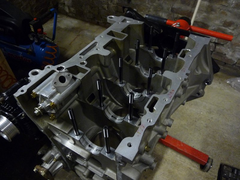

ARP Mains
Fitted the pistons to the rods, which was a nice clean and easy job with the fully floating pins. There's definately a knack to fitting
spriolocks though, and it seems to be a quick shove with a piece of dowel!
Also fitted the rings, which was a nice easy job, did them all by hand this time. I did check the ring end gap before fitting them to the pistons and
all seemed well.

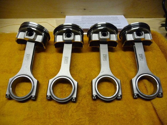
Rods and pistons
Next the pistons and rods were fitted to the block. Also fitted the ARP head studs

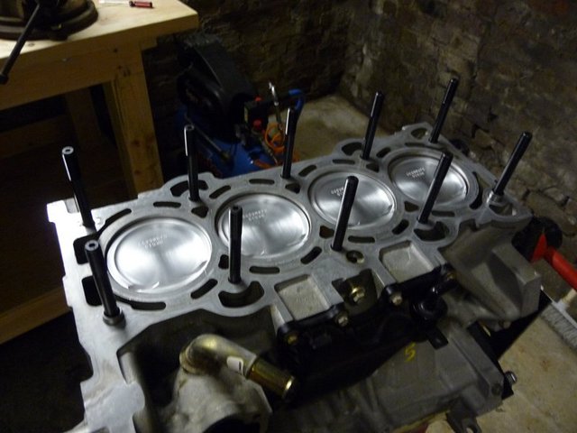
ARP head studs
Closer examination of the head reveals 4 bent exhaust valves from when the exhaust cam snapped. More expense which I could do without at the moment.
Its looking more and more like the engines not going to be ready and the whole projects slipping behind at the moment.
Next job is to take the crank to be modified by Scholar on monday morning, this can then be refitted back into the block 
David
beaver34 - 21/11/09 at 06:50 PM
i can sort you new valves out cheaper than retail, you still have my email?
goaty - 22/11/09 at 11:06 AM
how much did you manage to get the arps for in the end?? were Arrow useful??
And i spoke to Scholar about my bottom end, been there for 3 weeks now and on Friday they hadn't even started....lol. No prob as i dont have time
anyway at mo.
cant wait to see mine looking like that 
flak monkey - 22/11/09 at 11:48 AM
Got them from arrow, £75.15+vat so cant complain really!
I am taking my crank down to Scholar on monday and they are doing it while I wait  hopefully anyway!
Going to get both my ali crank pulley and the std one keyed I think.
David
goaty - 22/11/09 at 05:14 PM
cool, progress is being made. cant wait to see both done 
flak monkey - 23/11/09 at 07:22 PM
Another busy day today.
Took the crank down to Scholar Engines in near Stowmarket to get the crank keyed. Top job and turned it around in 2 hours for me as well! So I was
home just after lunch.

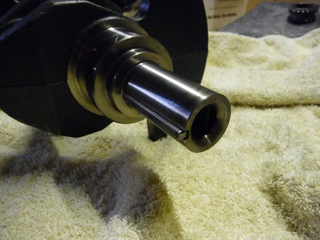
Keyed crank

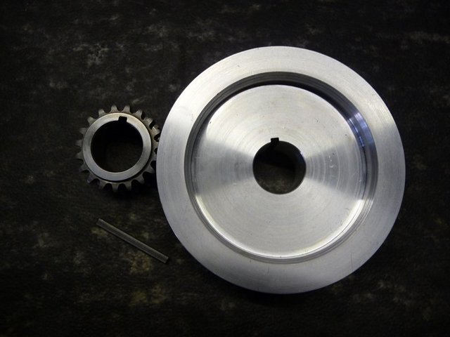
keyed pulley and gear
Cleaned it all up and fitted to the block. Torqued up the ARP main studs then fitted the conrods to the crank, again with ARP bolts.

Crank and rods refitted
Then fitted the gear to the crank and the oil pump and fitted the modified oil pick up pipe.

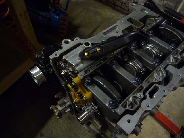
Oil pump drive
I also nearly finished modifying the chain cover. The engine mount is redundant and possibly in the way of the belt so I cut it off with the grinder.
Still need to tidy it up a bit, then probably paint the cover to tidy it up, though I may not.
This is the std front cover with the fwd engine mount

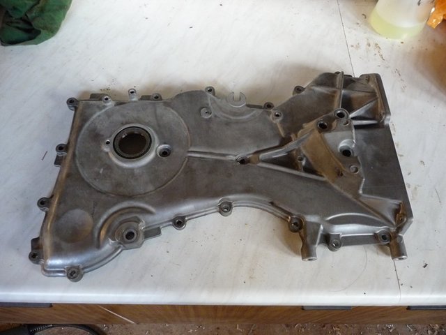
Std front cover
And this is the same cover with the mount removed

Modded front cover
I will make some bungs for the old bolt holes too as they arent required any more either. Or I could counterbore the holes and fit cap heads. Not
really decided yet!
matt.c - 28/11/09 at 07:50 PM
New garage needs a nice girly calendar on the wall 

Engine is coming along nicely now. Can wait to hear it running. 
flak monkey - 6/12/09 at 07:48 PM
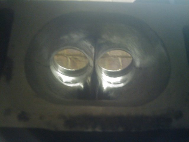
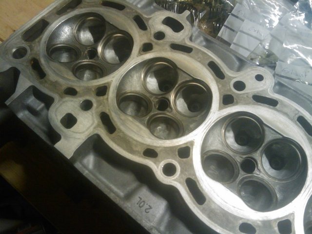
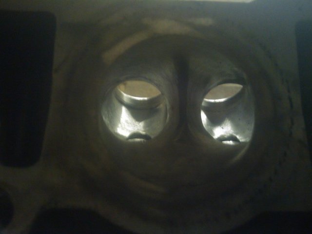
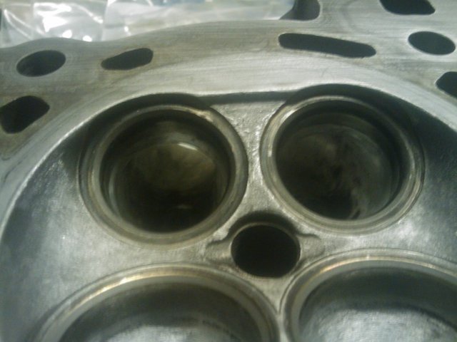
Been fettling the head and getting it ready to fit this weekend, in amongst pulling some ceilings down in the flat. So all in all a productive and
destructive weekend all around!
I took the oppotunity while the head was off to remove all the casting marks from the ports and smooth off the short turns in the inlet ports as these
had a sharp edge in, similar to that seen in the early pinto heads. Other than that the ports are incredibly well shaped from the factory so I didnt
remove a lot of material.
My felxi shaft broke halfway through which means I couldnt really touch the dividers in the ports as I didnt have enough reach, that said they arent
bad, and with the amount of turbulence the supercharger is going to create I dont think it will matter too much!
I also removed all the sharp edges from the inside of the combustion chamber to prevent any hotspots then gave them a quick once over to smooth them
over. There isnt really a spotface for the valve inserts, which was good, so other than removing the edge, they were left as machined.
Final job was to lap the valves in which didnt take too long as the seats were in very good condition anyway.
Heres the pics of the finished article. Apologies for the crappy quality, forgot my camera today so these are off the phone!
Inlet ports:

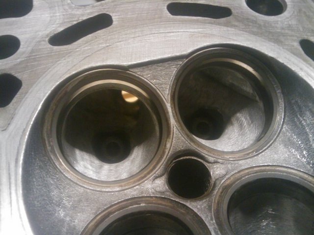
Head rebuild 1

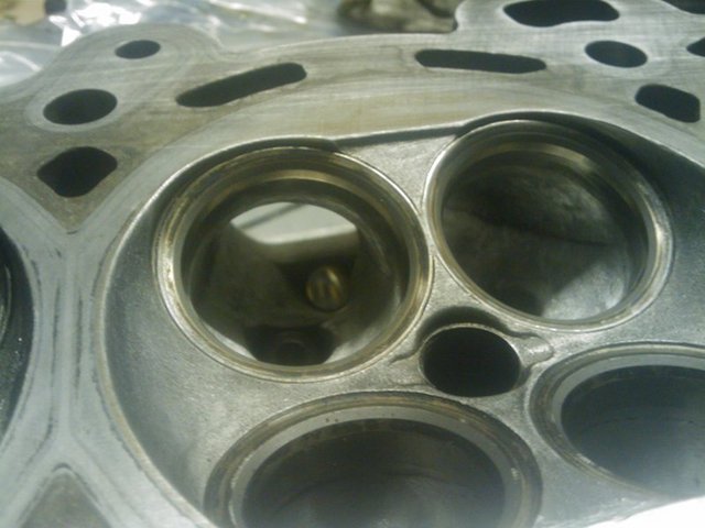
Head rebuild 3

Head rebuild 6
General view of combustion chambers:

Head rebuild 2
Exhaust ports:

Head rebuild 4

Head rebuild 5
All this was followed by a thorough hosing down and blowing all the passages out with the airline to remove all traces of swarf.
Just waiting for the uprated valve springs to arrive now. Thought it was worth fitting them now while the head was off, so if I decide to change the
cam at any time I dont need to take the head off again!
scootz - 6/12/09 at 09:51 PM
Very nice!
[Edited on 7/12/09 by scootz]
gdc - 18/12/09 at 08:20 PM
slightly of topic , i have in the last 12 months fitted an st170 engine its badged as a duretec but its i think a transition engine between the zetec
and duratec .
cast block and ally head but with vvt .
with A very restrictive ex manifold ie a standard rhsc zetec one its producing over 200 bhp on jenvies and megasquirt mapping .
by the way i do like the look of that duratec engine ,
all the best with the project graham
flak monkey - 18/12/09 at 08:33 PM
Thanks Graham
Yes the ST170 is a zetec engine with VVT for the extra power 
I have done a bit more today, but will put a full on update on at the end of the weekend.
All being well the engine will be fully build, new sump fitted and everything ready for the car. Then it will be on to making the supercharger
brackets 
flak monkey - 19/12/09 at 05:11 PM
A little more progress today. I can't feel my toes, but there we go!
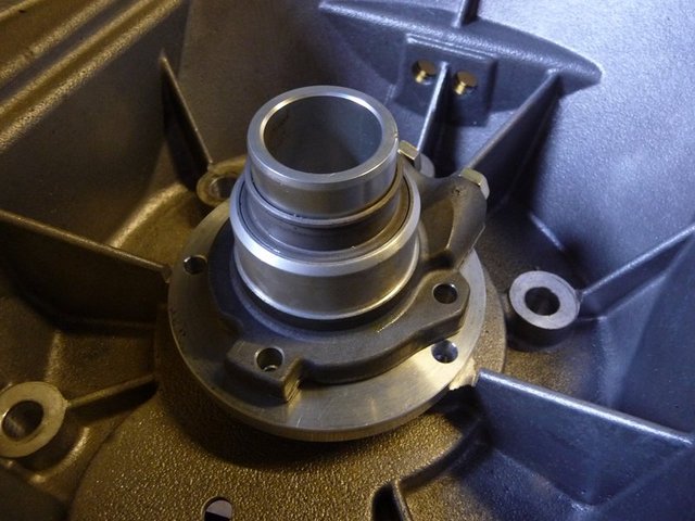
This morning I made my clutch slave cylinder spacer. I skimmed a bit of material off the bellhousing so I could make a spacer thick enough to
counterbore the heads of the SHCS into it.
Not bolted it in yet.

Clutch spacer
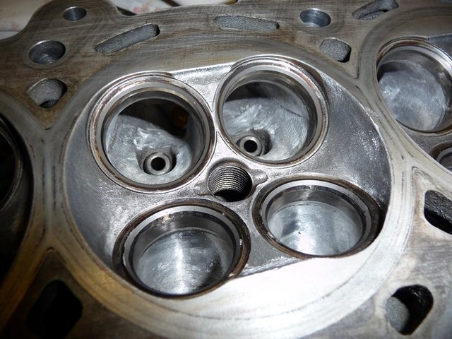
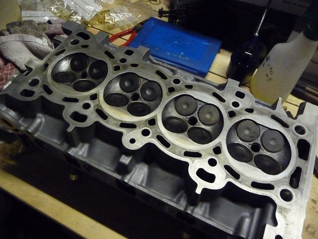
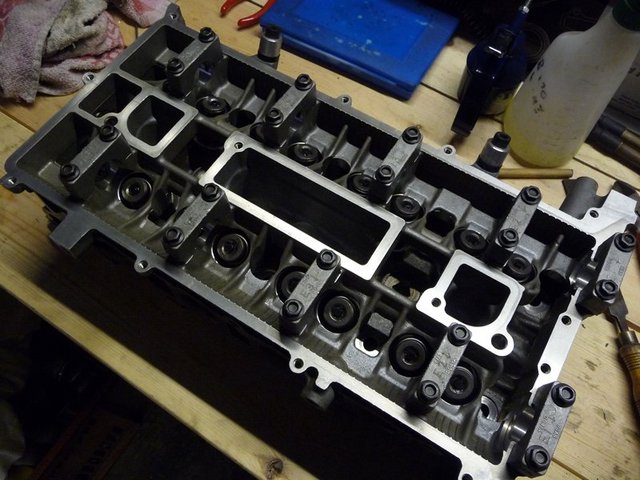
Refitted all the valves to the cylinder head yesterday afternoon. Bit of a tedious job. Found the best way to refit the collets was with some grease
on a screwdriver, unless you have really small fingers!
Springs were replaced with uprated kent cams ones as the standard ones are a bit weak.

Head rebuild 7

Head rebuild 9

Head rebuild 10
Then I set about refitting the cylinder head. Lubed up all the ARP studs before slipping the head on as its virtually impossible to reach them once
the head is on. Used some grease in a socket to fit the nuts and then torqued it all up.

Head on
Once that was on I refitted the camshafts and torqued the caps. Then checked all the valve clearances, looks like I will need a few new buckets!  More expense!
Then I fitted the new sump. Leak tested it last night and all seemed ok, then fitted the windage tray and then cleaned it all out again. Sprayed it
with high temp paint this morning before starting the other jobs. Its more silver than it looks in the pics.
Put a bead of loctite 5900 around the flange and popped it on the engine. A bit of a fiddle to ensure the flaps dont get stuck in the wrong place.

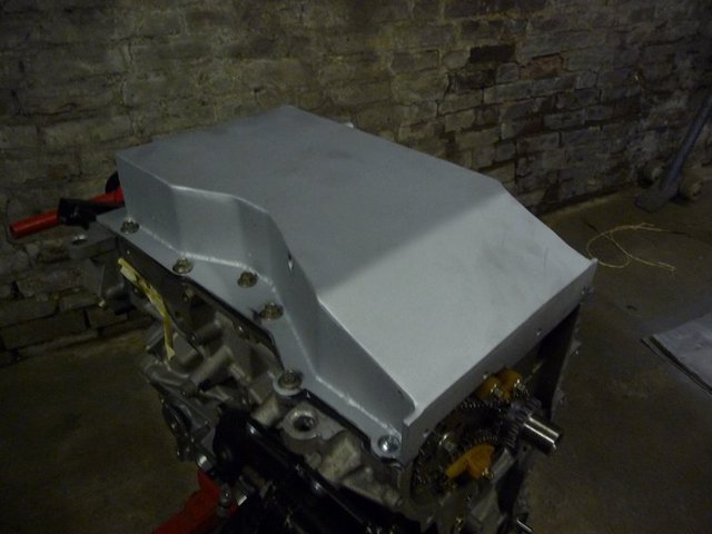
Sump fitted 1

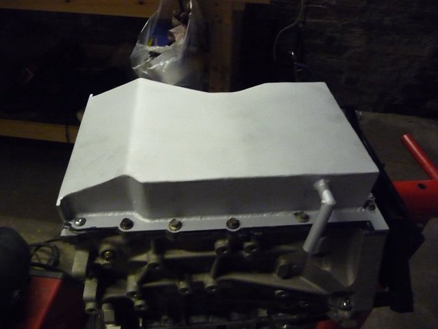
Sump fitted 2
Think that will probably be it for this weekend, too damn chilly out!
FASTdan - 20/12/09 at 09:54 AM
Looking good!
Quick question - how the hell does the alternator tensioner work on these engines?
We have the one from the 2.0 mondeo (but will be using the 1800 foci one as you have) but it looks like they both operate in a similar manner.
Are they sprung? We cant get ours to move in any direction at all?! It has a couple of arrows on but we've had it in a vice etc trying to move it
but no luck?
Is there any adjustment in them?
flak monkey - 20/12/09 at 11:15 AM
Hi Dan,
The focus one swivels.
Looking at it from the front (pulley side) it should be spring loaded if you try and turn it anticlockwise. Put a big spanner on the hex in the middle
of the pulley and try to turn it anticlockwise and it should move against the spring.
The mondeo one is also similar but fits on the bottom left of the block.
David
goaty - 20/12/09 at 12:11 PM
lloking awesome now David, i do love the look of a nice lean engine coing together. And i guess the Kent springs arrived first...lol.
manaed to get some done on mine yesterday too, but was too cold. will load some pics too 
FASTdan - 20/12/09 at 09:12 PM
quote:
Originally posted by flak monkey
Hi Dan,
The focus one swivels.
Looking at it from the front (pulley side) it should be spring loaded if you try and turn it anticlockwise. Put a big spanner on the hex in the middle
of the pulley and try to turn it anticlockwise and it should move against the spring.
The mondeo one is also similar but fits on the bottom left of the block.
David
I thought that must be how its supposed to work, Will have to give ours another try. So to install the belt presumably you use the spanner to relieve
some of the tension then wrap the belt over and release?
Still need to get hold of a focus tensioner.
flak monkey - 21/12/09 at 12:48 PM
Thats correct. Turn tensioner anticlockwise with spanner, then slip the belt over and release.
Micael - 21/12/09 at 07:15 PM
quote:
Originally posted by flak monkey
Flywheel part number
Just for information
The flywheel Flak is using can be found on
Ford Focus 2004-2007 1.8 petrol, with engine code Q7DA.
[Edited on 21/12/09 by Micael]
flak monkey - 22/12/09 at 04:16 PM
Ahh I just read brooke cars have squeezed 400bhp out of a supercharged duratec! 


Micael - 22/12/09 at 06:32 PM
add this head and you can go even further 
http://www.motordesign.se/start.asp?page=3en
goaty - 23/12/09 at 09:45 AM
wonder what that costs....I know a race head is looking the best part of £1300
flak monkey - 27/12/09 at 07:56 PM
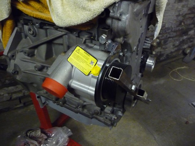
Got the supercharger mount 90% finished today. Need to tidy up some of the welds and cap the ends of the box section.
The box is 20x20x1.5, the laser cut plate is 6mm steel. The box has crush tubes welded in where the bolts go through.
The alignment is pretty good I think. Within about .25mm. Having had a measure up for a shim, it only needs a 0.7mm shim behind the front bolt at the
bottom to make it spot on.
Having done some calcs the supercharger is going to pull around 15bhp at 7250rpm and 14psi boost. Hopefully the brackets will take it.

Charger mounting 4

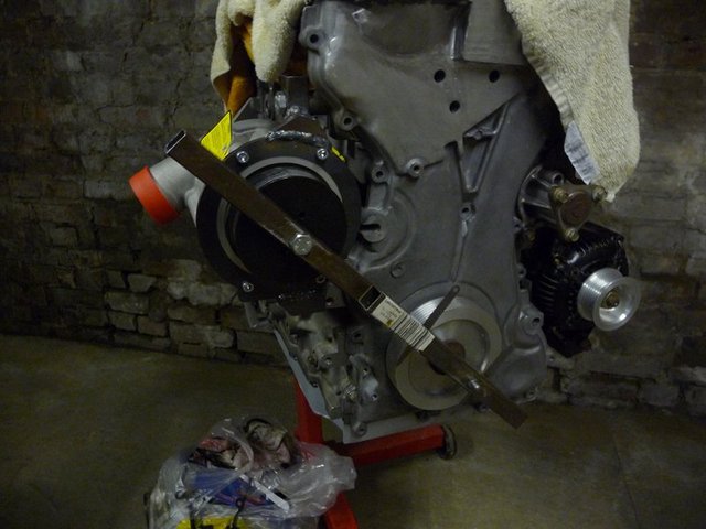
Charger mounting 5

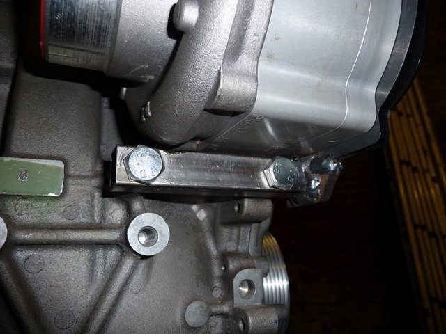
Charger mounting 6

Charger mounting 8

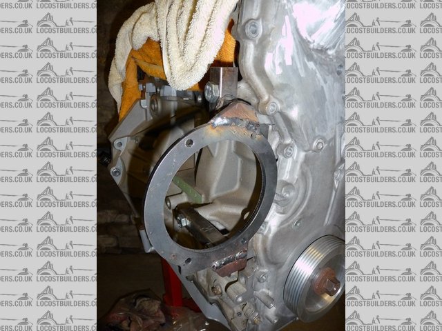
Charger mounting 9
[Edited on 28/12/09 by flak monkey]
goaty - 28/12/09 at 08:13 PM
looks very good dave, looks nice and tight to the block too which is vital 
flak monkey - 28/12/09 at 08:18 PM
Thanks, yep theres not much space. The laser cut plate is touching the front cover, I need to trim a little off it. Theres just enough space to get
the oil feed banjo on next to the block 
Had a measure up today and defo need to move the steering column. Will wait to get the engine in and see where its going to fit!
goaty - 28/12/09 at 08:20 PM
lol, i was thinking the same. may have to move a few bits and bobs
sebastiaan - 28/12/09 at 09:02 PM
15 HP at 7000RPM (i'm assuming crank and compressor pulley are approximately the same diameter) equates to 15Nm of torque or, when using a pulley
diameter of 3 inch, roughly 200N of force on the outer edge of the pulley. Looking at the brackets you've made, the compressor might try to
rotate around its height axis. Could you add a gusset between the box section of the bottom mount and the lasercut compressor mount plate to prevent
this? It looks like it would need to be below the box section and that you'd need to switch to allen bolts.
Does this make sense?
[Edited on 28/12/09 by sebastiaan]
flak monkey - 29/12/09 at 08:44 AM
Thanks for that.  I did wonder about fitting a gusset at the bottom. Would need to weld another piece of plate on along the bottom of the laser cut
plate though.
I understand where the torque fig comes from, but not sure about the force one?
If the pulley needs 15Nm of torque to turn it at 7000rpm then the force is the radius of the pulley divided by the torque isnt it? So for a 3"
pulley that would equate to 400N.
The pulley on the supercharger is 95mm OD so the force would be 315N or ~32kg. I may end up with a smaller pulley though, depending on how much boost
is lost in the rest of the system and how mental I feel once I have driven it for the first time!
ETA: Just found this
http://www.tribology-abc.com/calculators/e3_5a.htm
Plugging the relevant numbers in gives a shaft load of 302N so the calcs above arent far out.
[Edited on 29/12/09 by flak monkey]
flak monkey - 30/12/09 at 04:31 PM
Finished the supercharger mount yesterday morning, and just made myself a shim to align the pulleys perfectly.
Incidently I found that Gates specify a maximum shaft parallelism error of 0.25 degrees for poly vee drives.

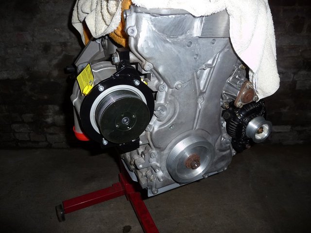
Finished charger mount 1

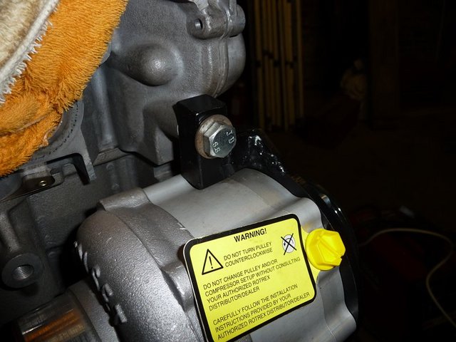
Finished charger mount 2

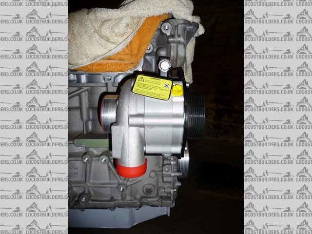
Finished charger mount 3
I have also been having a looking at where to put idlers for the best belt wrap on the crank pulley and the supercharger pulley.
I think one of the standard Duratec idlers will work between the crank and the alternator. Need to just swap the bolt out for a 10mm one.

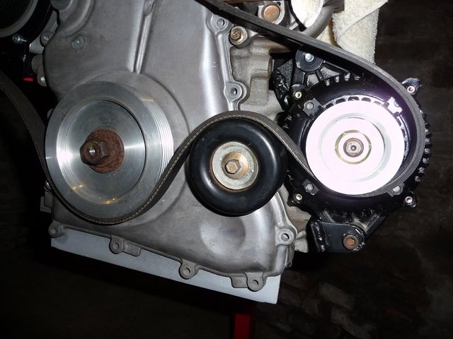
Idlers 2
I then need to make 2 more, a 45mm and 50mm one for either side of the supercharger pulley
Snap-off - 30/12/09 at 08:38 PM
Fantastic work Flak! 
That is going to be mental, wish I had the time to tinker again, would love to do another project.
Keep up the good work mate!
flak monkey - 31/12/09 at 02:07 PM
Took delivery of a set of Nissan Sunny GTiR throttle bodies with their plenum today.

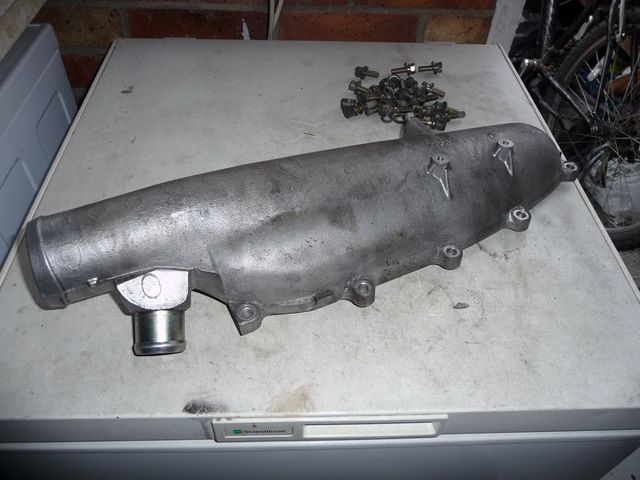
Plenum 1

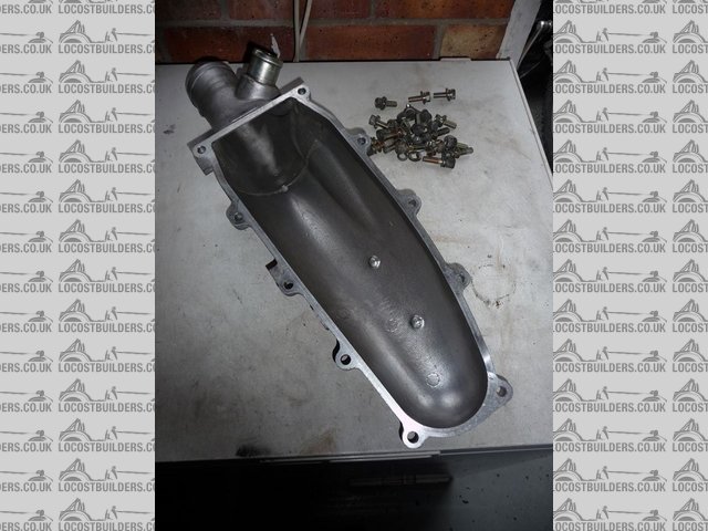
Plenum 2
Its nicely shaped and has a handy port for the dump valve to be fitted to as well. Its also exceptionally lightweight - which suprised me somewhat.
The idea is to use the plenum, with a modified backplate connect to my GSXR throttle bodies.
I will probably cut the back out of the existing backplate (below) and then have a 5mm thick aluminium plate welded in with stub tubes to suit the
GSXR throttle bodies. Then I just need to figure out how to bolt it all together so it doesnt blow itself apart.

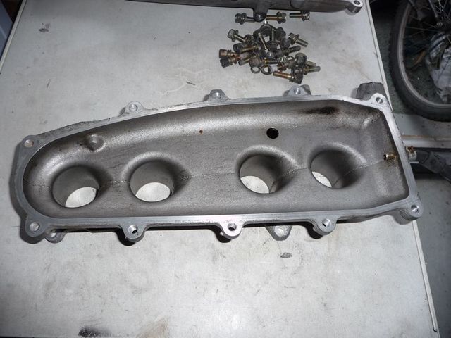
Plenum 3
The port spacing of the throttle bodies does match the Duratec, but sadly I cannot see a way to mount them up to the head particularly easily. Not and
keep the flow into the head nice and smooth anyway.
flak monkey - 2/1/10 at 04:55 PM
And this is what I intend to make to mate the plenum to the throttle bodies.
The plate is 6mm laser cut aluminium. The adaptors to fit on the throttle bodies fit into this, held on with 4 off M4 dome head screws, loctited
in.
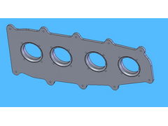

GTiR plenum adaptor cad
The adaptors themselves will be turned fom aluminium and glued to the throttle bodies with Loctite 648 retaining adhesive.
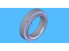

Hopefully it should make for a neat and compact solution to feeding the throttle bodies with the inlet charge from the intercooler 
flak monkey - 4/1/10 at 09:06 PM
Spent the last weekend before returning to work (yawn!  ) making the idler pulleys for the supercharger belt and modifying the throttle bodies to fit
the adaptors above.
Basically I mounted each one up in the lathe and took a few light cuts to clean up the outer ends

Modded throttle bodies
This will allow the adaptor plates to be glued on accurately. Just waiting for the material to arrive, then I can get those made.
Sent off the drawing for the plenum backplate today, just waiting for one to be laser cut now!
I also made 2 45mm dia idler pulleys to fit either side of the supercharger pulley to increase the wrap and to keep the belt out of the way of other
important things!
This highlighted the fact that I need to shave another 1mm off the front cover. The measurements suggest that this will leave it 2mm thick. If I dont
go too mad with the angry grinder!
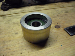

Idler pulley
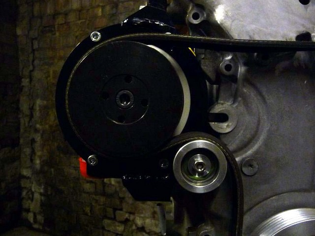
One goes here:

Idler pulley 2
And the other goes in the other bolt hole just below the belt in the pic. Gives loads of wrap on the pulley and hopefully will stop it slipping.
Another poly vee drive snippet of info. Gates' give a rough average of a max of 10hp per rib on poly vee pulleys. So quite a lot really!
Xtreme Kermit - 4/1/10 at 10:40 PM
Simply awesome work.
Keep it up!
FASTdan - 7/1/10 at 09:14 PM
Looking very good indeed. Good idea using the GTIR stuff - had no idea they ran individual TB's as standard.
I'm coming round to this supercharger lark.....
flak monkey - 16/1/10 at 06:05 PM
Finished the assembly of the engine today
Setting up the cam timing:
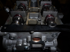

Cams fitted 2
Left the cam sprockets loose to allow the crank to be rotated to TDC before tightening the bolts up to lock off the cams.

Cams fitted 3

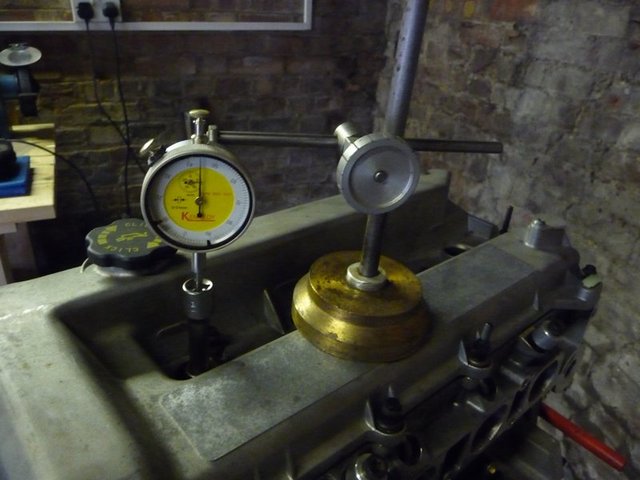
Finding TDC
I then fitted the front cover, sealed with Loctite 5900. Managed to shear one of the bolts off though, so will be drilling that out tomorrow!
Then fitted the new cam cover gaskets and fitted the cover. The water pump pulley. Just need to get some longer M6 bolts for the idler pulleys so I
can get them fitted and get measured up for the belt, which will no doubt be fun.

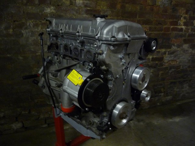
Finshed engine 1

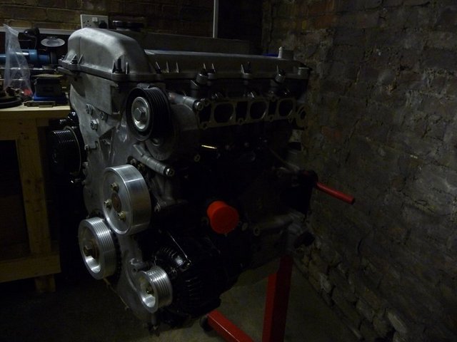
Finished engine 2
goaty - 16/1/10 at 06:22 PM
looking bloody awesome, really is coming together. I am waiting to see how it looks with the belt all fitted up, really am going to have problems
getting mine in so will help to see ways about bits and bobs.
Keep on trooping 
Benzine - 16/1/10 at 06:34 PM
Saucier than a direct hit on a Heinz factory!
flak monkey - 19/1/10 at 07:40 PM
Finished fitting the idler pulleys tonight, also got a rough idea of the length of belt needed. Looks to be around 2 to 2.1m

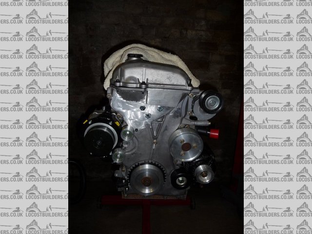
Pulleys finished 1

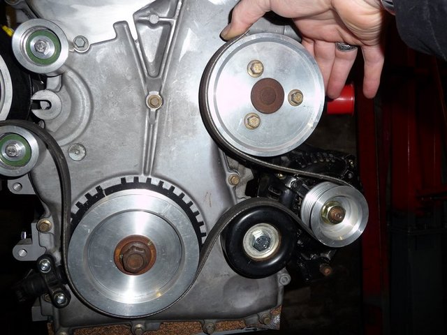
Pulleys finished 2

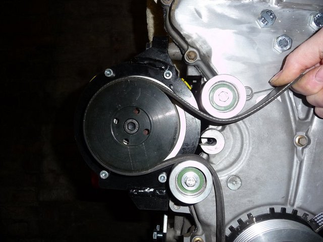
Pulleys finished
Looking forward to dropping the engine into the engine bay this weekend to see how it all fits.
Had a quick look at the steering column relocation as well. I might just get away with only one extra joint. 
David
goaty - 20/1/10 at 07:26 AM
hay dave,
where and what are them idlers from?? coudl do with a set my self....
Also, how have you fixed them all on??
cheers
flak monkey - 20/1/10 at 08:03 AM
I made them  I couldnt find any the right size.
I put highspeed bearings in anyway.
They are bolted into two of the front cover holes.
David
flak monkey - 20/1/10 at 06:11 PM
Another shiney present arrived today. A set of Caterham branded Cosworth roller barrels! 
They bolt direct to the cylinderhead, which means I might just be able to keep the plenum inside the confines of the bonnet for the sleeper look. They
are only 95mm deep without the trumpets fitted.
The intension is to make a backplate for the plenum to bolt direct to the throttlebodies now, rather than all the bits and pieces I was going to do
with the GSXR ones!
I just need to find some much shorter trumpets to fit so I can fit some inside the plenum.
Here follows much automotive pornography!
Oh noes, a box of newspaper!
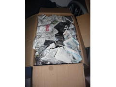

Roller barrels 1
Maybe not!

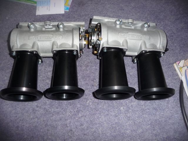
Roller barrels 2
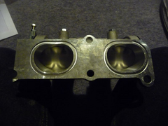

Roller barrels 4
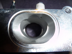

Roller barrels 5
I wonder if the Cateringvan lawyers will mind? 

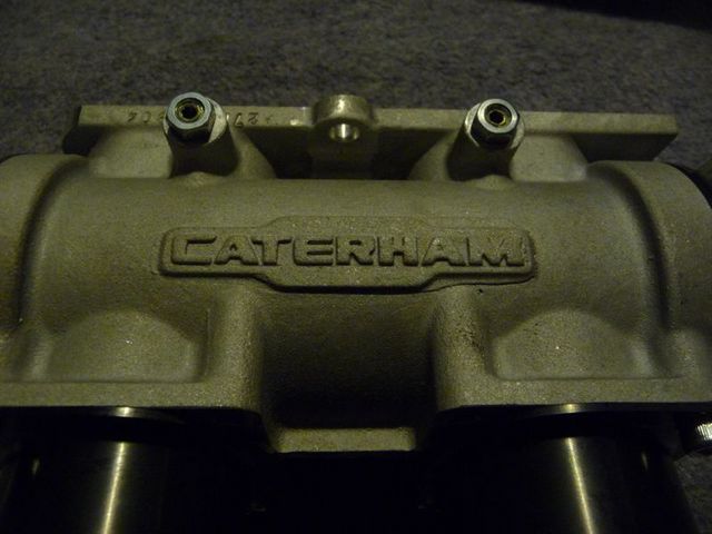
Roller barrels 6
And the final thing is I need to find a TPS to fit on here:

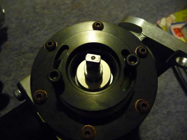
Roller barrels 3
I know what I will be doing tomorrow evening 
goaty - 20/1/10 at 07:42 PM
looks like ford zetec E tps woudl fit that, i do happen to have one lying about too 
ps, may get in touch about some idler's too if cool, still got issue with dry sump though, would have to make all the bits to move it
across....not good. lol.
flak monkey - 21/1/10 at 07:27 PM
Just fitted the new roller barrels. Snug fit next to the tensioner, and looks like I will need an additional spacer to allow the plenum to clear the
tensioner. I guess the other alternative is to change the tensioner.

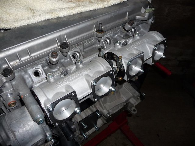
Roller barrels fitted 1

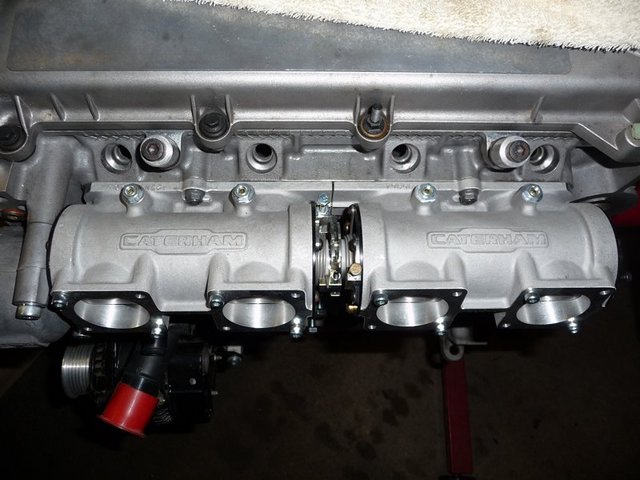
Roller barrels fitted 2
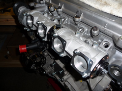

Roller barrels fitted 4
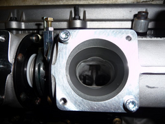

Roller barrels fitted 3

goaty - 21/1/10 at 08:10 PM
caterham parts show one for non roller barrell so assume the other is for roller bearings. or could go for raceline 
flak monkey - 22/1/10 at 12:49 PM
The tensioner fits ok, its the fact I need a spacer to make the plenum clear it now 
Will get all the bits for the plenum laser cut in the next week or so.
Also expecting my radiator/intercooler in the next couple of weeks 
flak monkey - 22/1/10 at 07:49 PM
Big day today. Decided to get the engine trial fitted in the chassis, thankfully everything seems to fit and I am very pleased that I put the
supercharger on the exhaust side, I dont think it would have fitted in the chassis on the inlet side.
Fitted the bellhousing to the engine as this will determine the fore/aft position of the engine in the chassis ultimately.

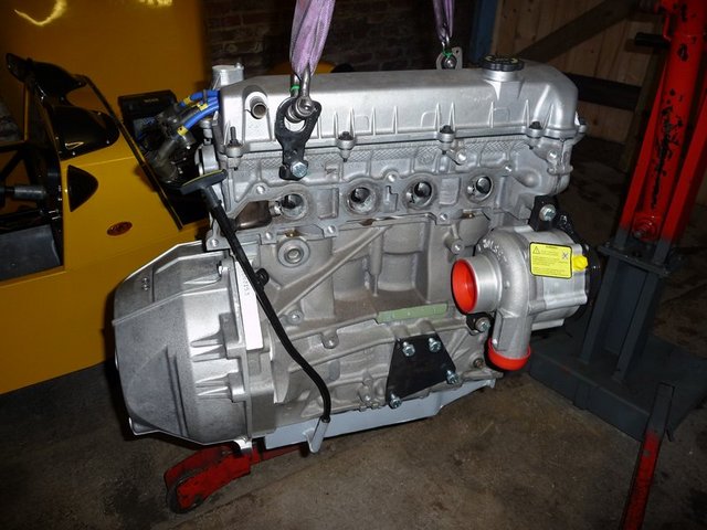
Engine test fitting 1

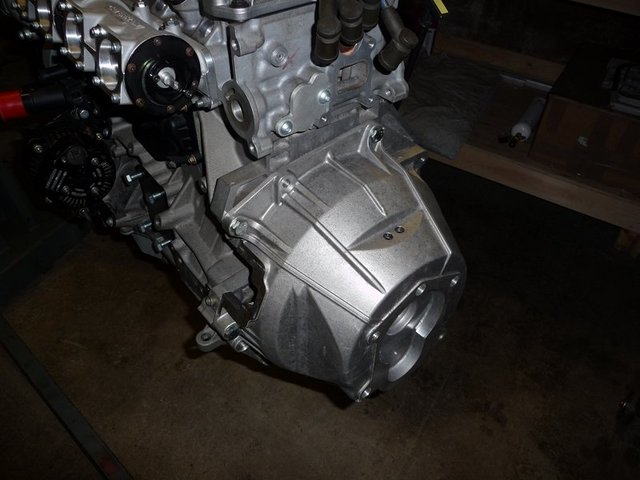
Engine test fitting 2
Then dropped the engine into the bay (obviously with the nose off to start with!)

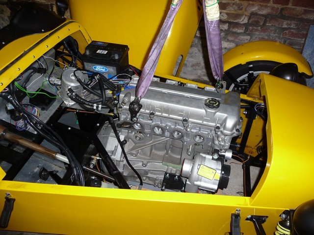
Engine test fitting 3
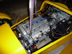

Engine test fitting 4
Then spent a little time getting the height right. There is about 5mm clearance to the bonnet, which should hopefully be enough. I could alway make a
new lower profile cap at a later date.

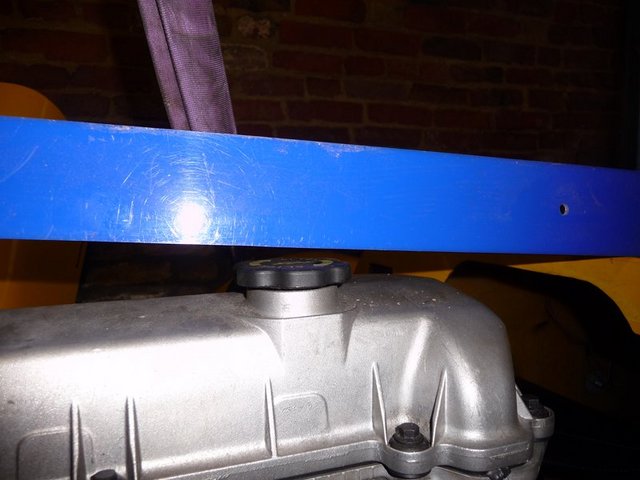
Engine test fitting 5
The sump will be around 25mm below the chassis, which is less than the pinto was, so I will end up with a little more ground clearance 

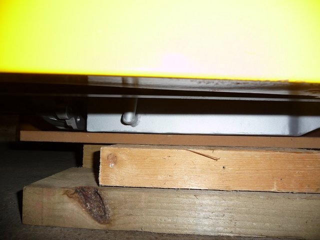
Engine test fitting 10
Thankfully only one more joint is needed in the steering column and the rally design plined column is exactly the right length for the second link. So
now I need to make some supports for some rose joints to hold this part.

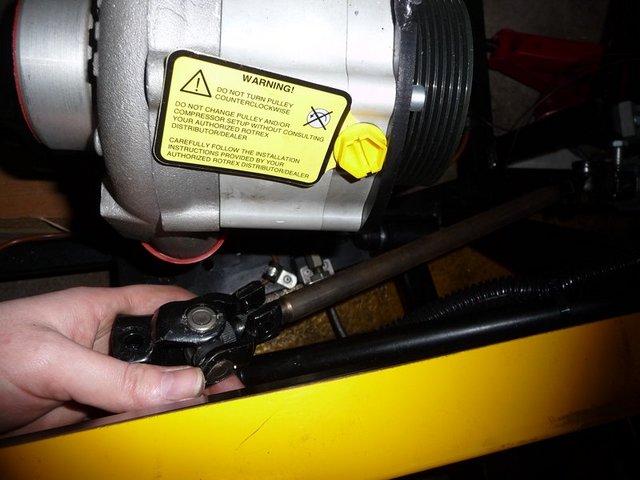
Engine test fitting 6
Theres around 25mm clearance all around the bellhousing cut aways. Which is nice. The engine can't really go any further back anway. In this
position the gearstick should also be in about the right place I think.
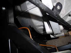

Engine test fitting 7
Theres about 10mm between the alternator bracket and the brake pipe. I need to make a new pipe anyway, so will try and make some more room around
here

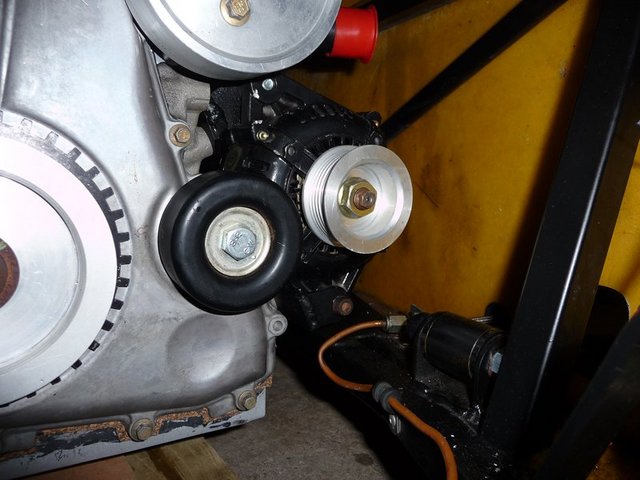
Engine test fitting 8
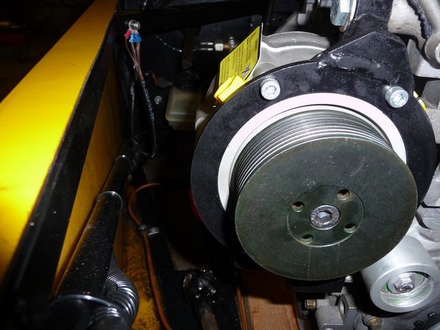
But plenty of room around the rotrex for the column

Engine test fitting 9
Tomorrows job is to make the engine mounts and steering column support mounts too 

Engine test fitting 11
[Edited on 22/1/10 by flak monkey]
goaty - 22/1/10 at 08:05 PM
looks very good. does fit in nicely. Think i will have to move two chassis rails, the two diagonals coming forward each side of the engine on mine
come alot further forward at less of an angle. Can move them to be like yours with no problems.
Great to see it in the car though, bet your well pleased 
daniel mason - 22/1/10 at 08:39 PM
what sort of height differene or how much lower would a honda s2000 motor sit in the chassis as you seem to have plenty of room!
flak monkey - 22/1/10 at 09:45 PM
As far as I know the S2000 is a bit of a large engine. I have seen a dax with one fitted, the engine had to be mounted at an angle to get it in (
perhaps matching the std install?)
The gearbox is quite large as well
sebastiaan - 23/1/10 at 09:41 AM
Looking good there David! It seems to be far enough backwards in the 'ole!
Have fun making the engine mounts, but it might be a good idea to do one more trail fit but with the gearbox attached? If it does not fit now and
you've already made the engine mounts you would need to redo them or do a chop-chop job on the tunnel...
flak monkey - 23/1/10 at 07:15 PM
Thanks Sebastiaan, I did fit the gearbox this morning as I was thinking the same thing 
The gearbox is snug, but theres at least 10mm clearance all around. It physically cannot go any further back though.
I need to tidy up where I roughly ground off the old gearbox mounts this morning. I will be making new ones tomorrow from box section.

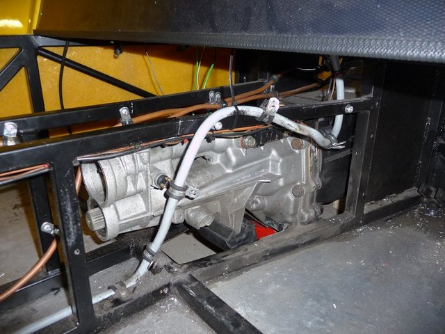
Gearbox fitted 1
I will be modifying the westy/caterham gearbox mount slighty to allow me to fit a piece of 20x20 box each side to bolt it to.

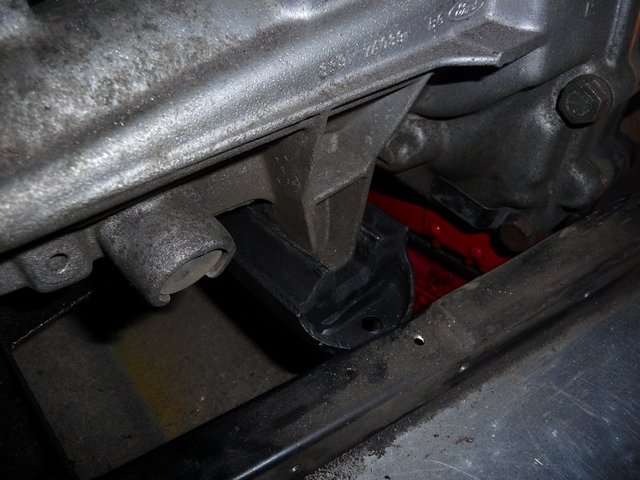
Gearbox fitted 2
There's not an awful lot of room down there. The brake pipe is actually well away from the box, not how it looks in the pic, must be the angle

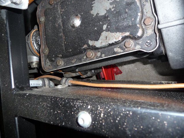
Gearbox fitted 3
Made the engine mounts today. A job which seems to have taken all day for some reason, but never mind! They will of course be painted at a later date!
For now they are supporting the engines weight.

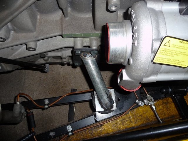
Engine mounts 1

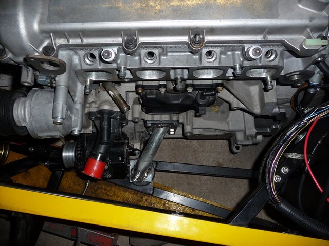
Engine mounts 2
And it all leaves me with a decent amount of ground clearance. Could even wind it down a bit if I wanted to. Theres about 4" to the sump now.

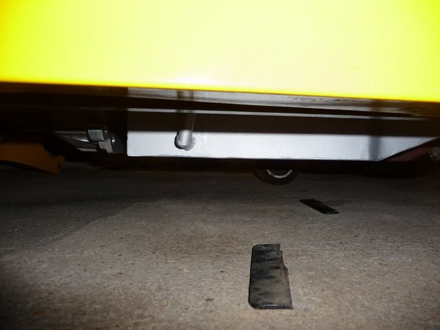
Ground clearane
[Edited on 23/1/10 by flak monkey]
flak monkey - 24/1/10 at 06:50 PM
Got the gearbox mounts welded in today. After a bit of hassle with the welder, think I could do with a new liner. No problem with the weld pentration,
just not very tidy! 
Anyway, made 2 closed end tubes with crush tubes in to bolt the westy gearbox mount to.

Gearbox mount
Will get a coat of paint on it one evening this week.
Had to split the engine and box again to fit the flywheel and clutch. St150 flywheel fitted with ARP bolts. Cover is an AP racing CP3560-2 rated to
230lbft of torque (expecting around 220lbft) and a competition AP racing pinto friction plate (CP5351-1).

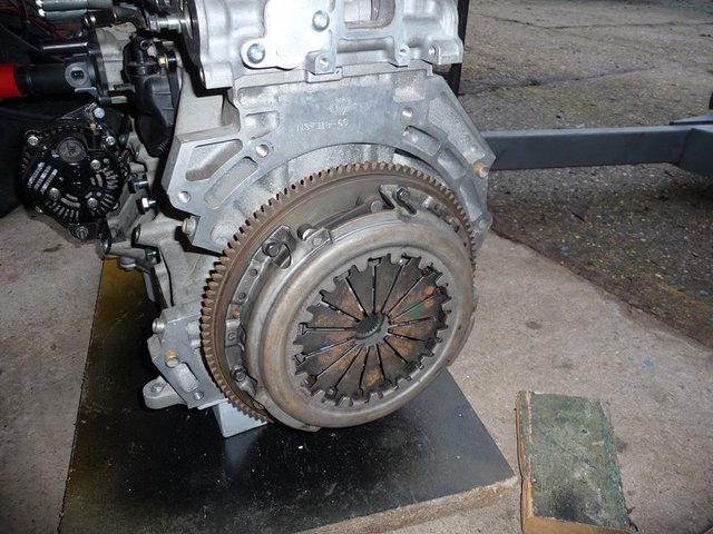
Flywheel and clutch fitted
Also spent a bit of time cleaning the car inside, as everything was covered in oil from when the pinto was extracted, and then covered in angry
grinder dust, so now a much nicer place to work 
Removed the old battery and now there's space for the shiney new one!
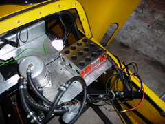

New battery
Seems like a few steps backward today as well as the engine and box are out again and wont be back in until I have a new prop shaft. 
Next job is to determine how much clutch pedal travel I need to get the release bearing travel I need. Which means getting some adaptors made for the
hydraulics. Then I can get the master cylinder fitted and new clutch pedal made next weekend. Also need to start thinking about finally fitting the
battery, swirlpot, rotrex oil tank and header tank on the footwell tops. Should be enough space anyway. I would also like to get the steering column
refitted with the extra link.
[Edited on 24/1/10 by flak monkey]
Breaker - 26/1/10 at 10:00 AM
You did a veeeeeery nice job !
Although I think you can get much nicer (better) welds with a TIG.
eddie99 - 26/1/10 at 11:27 AM
Looking real nice. Really can't wait to see it running and driving 
Stuart_B - 27/1/10 at 07:13 PM
nice porgress david.
i will soon chasing a new engine conversion, as the duratec did not do so well.lol
stuart
goaty - 28/1/10 at 11:52 AM
just a quick one, what are you planning for a fuel pump??
i am sitting just looking for bits right now...lol 
flak monkey - 28/1/10 at 12:01 PM
I am using a GSL392 external pump to feed the fuel injection:
http://store.looseboltsmotorsports.com/waexfupu.html
Really small pump (about 2/3 the size of a bosch) and the same flow capacity. 70US gallons/hr
And a red top facet to keep the swirl pot topped up. Although the facet cannot supply enough fuel to run the pump flat out all the time (45us gal/hr),
the 2 litres in the swirl pot should be enough buffer.
The only low pressure pumps I could find to supply enough fuel to match the GSL392 were american V8 pumps.
As a general rule, multiply your BHP by 0.47 to get your fuel requirements in litres per hour for forced incduction. So you want at least 155lph pump
(assuming 330bhp) which is 40US GPH so maybe a redtop will be enough for flat out....
goaty - 28/1/10 at 10:51 PM
wonderful, cheers dave. i will have a little look at some
flak monkey - 31/1/10 at 06:16 PM
Slowish weekend this one, for 2 reasons. 1 its been bloody freezing and 2 I managed to damage myself on saturday morning, meaning I only have the use
of one opposable thumb at the moment 
Anyway...
Friday evening I made a special M12x1 to -3 hose fitting for the bleed connection to my clutch slave cylinder. They are prety simple to make really,
and I dont know why I didnt do it sooner.
This meant I could get the cylinder finally fitted to the bellhousing so its ready to be finally bolted up to the engine next weekend. The main feed
hose is -4 as this seemed more common for clutches.
All bolts were loctited in just to be on the safe side as they arent biting on much thread

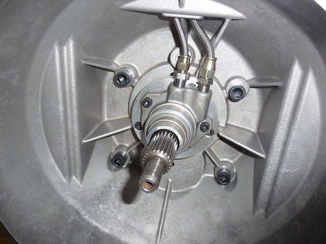
Fitted slave cylinder
I also, thankfully, checked the operation of the gearbox before finally fitting it to the car and found I couldnt select gears properly. I had
forgotten to correctly locate the centring bit on the selector shaft and it was catching on another part. All fixed now though 
Next job was to make the mounts for the steering column downlink bearing. I have decided I will be adding in another tube yet. I intend to add another
down from the diagonal to the nut holding the rose joint, as due to the length of the current one Its not going to be strong enough long term. Will
get that done next weekend, and then get all the bits painted.. All being well the column will now clear the supercharger!
I had to make a sleeve for the column to pass through the rose joint, just drille dout a piece of steel tube and spot welded it to the shaft, then
turned the lot down in the lathe so it was a nice sliding fit for the joint.

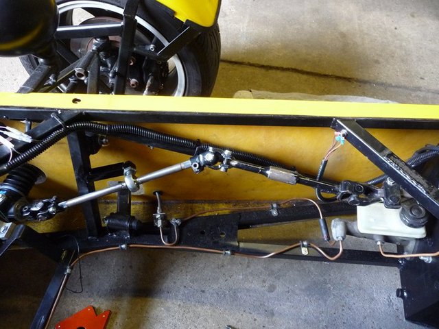
Steering column modded 1

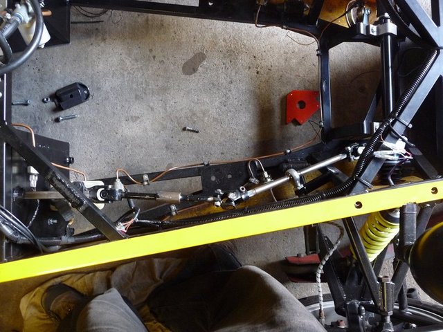
Steering column modded 2
The job for today was drilling and tapping all of the plenum parts. I had the plates water jet cut by andyw7de who did an excellent job, and very
quick too (5 days turn around).
There are 3 plates, 1 spacer plate to give a little more room inside the plenum, this is 1/2" thick. 1 back plate for the plenum which is 8mm
thick and then a spacer plate to space the plenum out enough to clear the tensioner, this is 3/4" thick.
Backplate and spacer after drilling and tappping

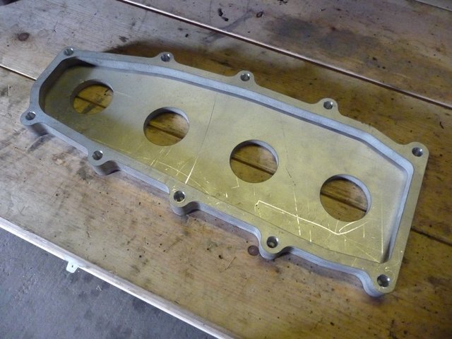
Plenum bits 1
3/4" spacer before drilling to suit throttle bodies

Plenum bits 2
And the final thing after lots of marking out and drilling! Hopedully it will all fit nicely.

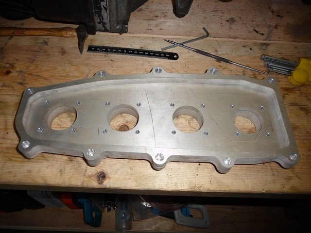
Plenum bits 3
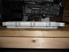

Plenum bits 4
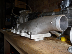

Plenum bits 5
Next weekend its time to sort the clutch pedal and slave cylinder mountings. Remake a couple of brake lines, then move the fuel feed and return. After
thats all done the engine can go in and stay in finally 

goaty - 31/1/10 at 06:53 PM
wow, very impressive dave, i wish i was able to spend as much time working on mine at the mo.
I think that your plenum will look awesome too, really is great fun to read through these pages 
westy turbo - 31/1/10 at 11:27 PM
Neet work!!!
Doing the same inlet at the moment,in a vx.but my air trumpets ned to b shortened,so they can face the back plate,got any pic from inside the plenum?
flak monkey - 1/2/10 at 03:09 PM
Not sure what you mean about pics inside the plenum? The inside looks exactly as shown above....
I will be fitting the shortest trumpets I can inside the plenum, IIRC they are 15mm long. I also need to drill and tap the backplate for the air temp
sensor to fit into. Need to work out the temp curve for the cosworth air temp sensor......
Breaker - 3/2/10 at 01:49 PM
All this effort to squeeze out some more BHP out of a Duratec 
FYI: Soon Ford and Volvo will start selling cars with a 2.0 GTDI (Gasoline Turbo direct injection). The engine has about the same size as a Duratec
and will have 203 BHP / 300 Nm as standard.
I think in about 2 years, the GTDI will become the successor of the Zetec/Duratec in kitcars. 
flak monkey - 3/2/10 at 02:03 PM
quote:
Originally posted by Breaker
All this effort to squeeze out some more BHP out of a Duratec 
FYI: Soon Ford and Volvo will start selling cars with a 2.0 GTDI (Gasoline Turbo direct injection). The engine has about the same size as a Duratec
and will have 203 BHP / 300 Nm as standard.
I think in about 2 years, the GTDI will become the successor of the Zetec/Duratec in kitcars. 
You can get 200bhp from a std duratec with just throttle bodies anyway.
This should end up around 300bhp and 300Nm
Breaker - 3/2/10 at 03:50 PM
quote:
Originally posted by flak monkey
You can get 200bhp from a std duratec with just throttle bodies anyway.
This should end up around 300bhp and 300Nm
Ok, but direct injection petrol cars should be more fuel efficient.
A 2.0 GTDI with 240bhp/340 Nm will also be available later this year.
flak monkey - 3/2/10 at 04:27 PM
Fair enough, but I am not really interested in fuel economy.... 
Just been doing a bit more reading and 11psi will give 310bhp. Jamsport have run this level on a totally stock bottom end for 17,000miles with no
reliability issues.
My ultimate aim is 15psi, will be interesting to see what that gives.....
eddie99 - 3/2/10 at 04:37 PM
Recipe for speeding points surely 


iscmatt - 3/2/10 at 06:06 PM
quote:
Originally posted by eddie99
Recipe for speeding points surely 


also a Recipe for bragging rights! I can't wait to see and hear this car!
Stuart_B - 3/2/10 at 07:01 PM
i so which i could carry on with my install, as i was going to use a eaton supercharging in a few years time.
nice work david, i will love to this a some shows, and meet you would be good as well.
stuart
flak monkey - 3/2/10 at 10:41 PM
Should be at Stoneleigh, if all goes to plan....and it doesnt go bang on the way! 
goaty - 4/2/10 at 07:47 AM
optimistic 

I am the same with mine, hoping the fist time it turns over all gos well.
Another one for you.....Do you knwo what starter will work with my flywheel set up?
would a duratec ka one work?
cheers dave
flak monkey - 4/2/10 at 07:51 AM
What do you have again? I cant remember.
There are essentially 2 different starters, the mondeo one and the St150 one.
The St150 sits closer to the block as the flywheel is slightly smaller than the mondeo one.
I *think* all the aftermarket steel flywheels use the mondeo one.
The Ka engine is totally different.
David
goaty - 4/2/10 at 07:55 AM
titan flywheel so i need to find a mondeo one, or some smaller equivilant if there is one.
cheers david
ps, charger bracket is made so i can now look at mounting into the chassis to work out the alternator mounting....should be fun...lol
goaty - 4/2/10 at 10:54 AM
any news on your rad and coooler yet? mine wont be ready for another month yet  lol
lol
cant wait to see what they will come out like 
matt.c - 4/2/10 at 08:03 PM
Do i need to get my helmet and gloves out yet? 
Is it finished yet? 
flak monkey - 5/2/10 at 09:40 PM
The rad is done, intercooler will be sorted early next week hopefully.
Was hoping the prop would be ready this week so I could finally fit the engine, but sadly its not finished yet.
Looks like it will be next weekend for the final fitment now 
David
flak monkey - 7/2/10 at 03:30 PM
Very little progress this week. Crap week at work hasnt really put me in the best frame of mind for working on the car.
Did get a few little jobs done however...
Beefed up the steering column support, painted and fitted the column properly too. Seems much better now 

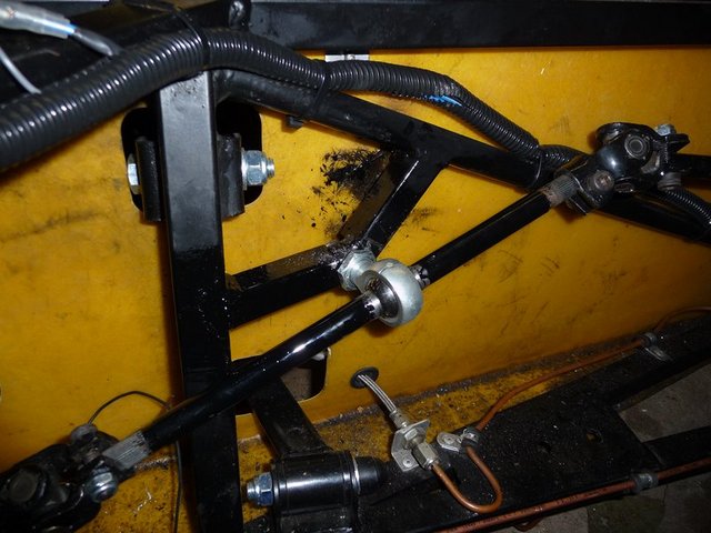
Steering column support

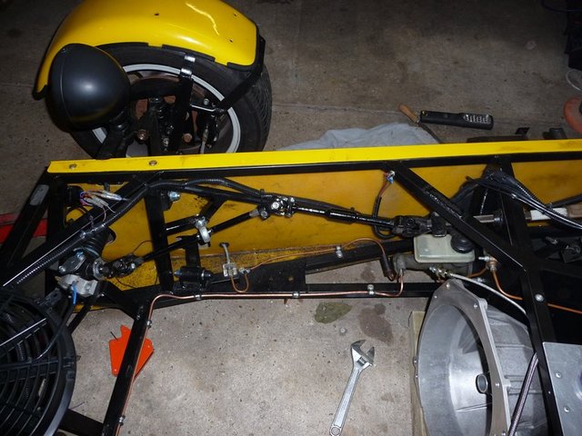
Column finished
Fitted the oil filter housing from Raceline, was expecting it until next week, but there we go  Fingers crossed the filter will clear the
chassis.
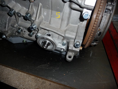

Oil filter housing
Bolted down the battery on the top of the footwell. Amazingly small compared to the old one, and will allow me to mount the header tank above it and
still clear the bonnet. This will leave me more room to fit the swirl pot and oil tank for the rotrex up on the footwells too.
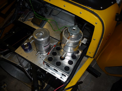

Battery and tanks
GRS also sent over some pics of the radiator which is nearly finished, just need to fit the bleed connection on the top of the right hand tank. Its
basically the same frontal area as a polo radiator, but is a twin tube core and the pipes are designed to clear the chassis better. They will be
making the intercooler this week, so all being well I should have that next weekend....
.JPG)
.JPG)
.JPG)
.JPG)
Hopefully things will go better next weekend and I can get the engine mounts beefed up and the engine finally mounted in the chassis.
FASTdan - 10/2/10 at 01:25 PM
quote:
Originally posted by flak monkey
Very little progress this week. Crap week at work hasnt really put me in the best frame of mind for working on the car.
All looking good - what do you do out of interest? I only ask as I assume design engineer perhaps? given the cad and general engineering knowhow.
flak monkey - 10/2/10 at 01:59 PM
I work as a project engineer, but am also getting more involved in production management more and more every day it seems....
The last couple of weeks have been hell as we had a load of machines down, but things seem to be picking up now *touch wood*
dlatch - 10/2/10 at 04:20 PM
that rad looks absolutley perfect
i dread to think but how much?
FASTdan - 10/2/10 at 09:45 PM
quote:
Originally posted by flak monkey
I work as a project engineer, but am also getting more involved in production management more and more every day it seems....
The last couple of weeks have been hell as we had a load of machines down, but things seem to be picking up now *touch wood*
Same here (project engineer). What do you make/design/build? We do special purpose machinery for the food and process industry (tobacco,
pharmaceuticals etc).
flak monkey - 10/2/10 at 10:03 PM
I work for a specialist bearing company. The projects are varied, I usually get involved in procuring new machinery rather than the site improvement
stuff. That includes everything from selecting the kit, justifying it, sorting tooling, capability trials, training, and long term support to the shop
floor. The machinery can be anything from £2k wash tanks to £250k+ grinders.
I also am responsible for the technical side of 6 manufacturing areas (3 turning (upto around 500mm dia) 2 grinding and hardturning (internal and
external) and the raw material cut off). If any of the areas have any technical problems they come and see me... so its pretty varied, but when
machines are out of action it becomes a nightmare.
Anyway as this is starting to sound like a CV....
GRS have just sent some more piccies of the radiator and intercooler over for my perusal  Looks like its coming on well. Theres just the tight 90deg
50mm tubes to weld on by the looks of it. The intercooler is 50mm core, and bolts to the front of the radiator. I will fit some strips top and bottom
to force any air that goes through the intercooler to pass through the radiator too...unless GRS beat me to it
.JPG)
.JPG)
.JPG)
.JPG)
And no its not cheap  But should be more than adequate!
flak monkey - 13/2/10 at 09:10 PM
Made a little more progress yesterday, and dropped the engine and gearbox in finally tonight. Need to torque the bellhouing bolts, but access is
easy.
Welded in some additional plates on the chassis, the intention being that tomorrow I will be spending the day beefing up the engine mounts by adding
in another tube and rubber mount on each one.

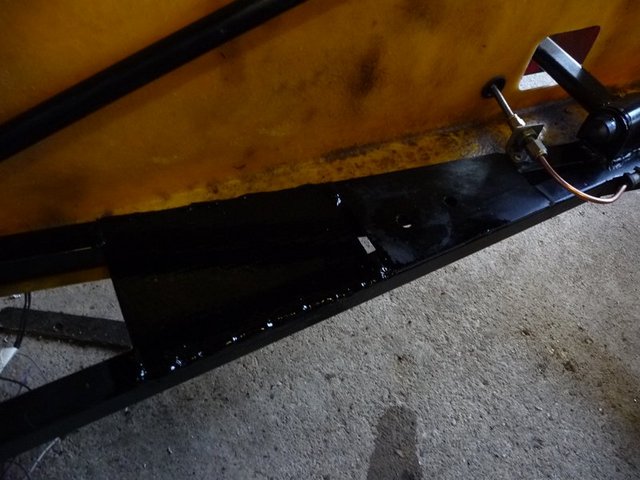
Mount plates 1

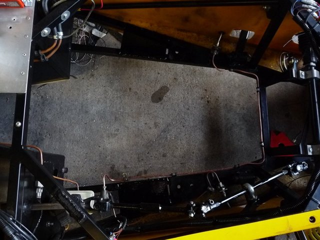
Mount plates 2
Drilled the hole in the bulkhead for the clutch master cylinder. Should give a pedal ratio of around 4.5:1 which should give a light enough pedal and
progressive clutch hopefully! Though yet to try it out...
Also made a new brake pipe to avoid the master cylinder and tidy it all up a bit as I never was happy with the original pipe work.

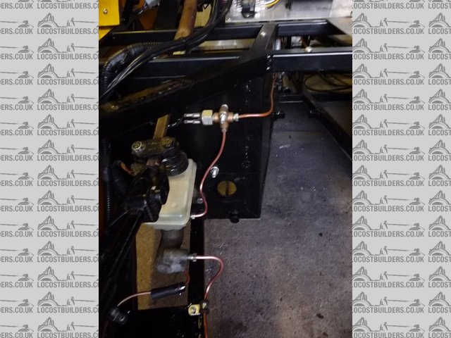
Clutch cylinder mount and new
Got the new prop fitted as well. Went for a heavy duty one from Dunning and Fairbank. Highly recommended, quick turn around (1 week) and beat everyone
else on price 

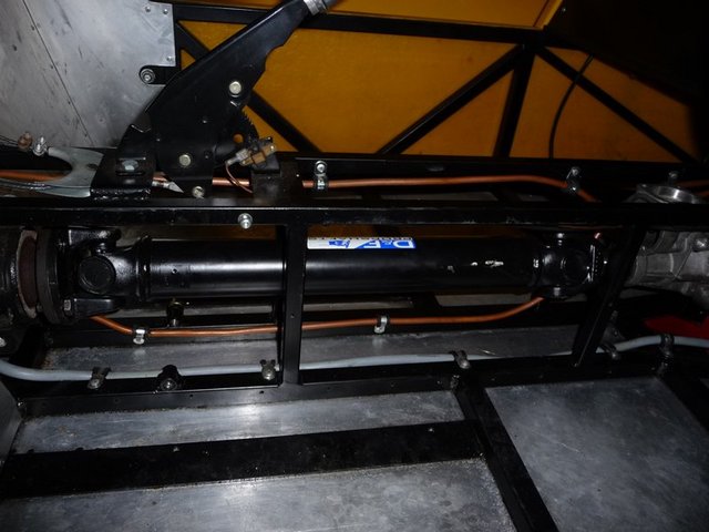
New prop 1
Thankfully theres loads of clearance between the supercharger and the column now, around 15mm all around.

Column clearance
Fitted the oil filter as well so I know how much room I have for the engine mount modifications. Thankfully there's plenty of room around
there.

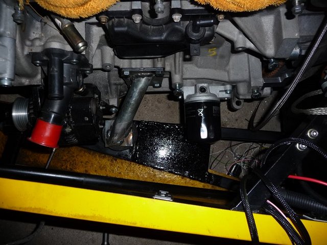
Oil filter fitted
Also looks like my intercooler and rad is nearly finished by the pics I have just had from GRS
.JPG)
.JPG)
.JPG)
goaty - 14/2/10 at 10:20 AM
looks very good, how tall is the cooler ocmplete with the pipe connections, they look like they poke up quite high.....worried abotu how tight it will
be.
And i got issues fitting my engine, it dont fit in the bay...lol. Moving some bits of chassis as we speak 
you dont realise how tight these engine bays are till you try...lol
Yours is looking very good now david, keep up with the pics etc, wish i'd done the same 
flak monkey - 14/2/10 at 07:09 PM
The dimensions are as in the drawings, think I posted them earlier in this thread somewhere...
Glad I didnt have to move any chassis rails!
Finished off the engine mounts today after concerns they werent up to the job. Hopefully now they should take the stick!
This pic shows the angle of the mounts from the front

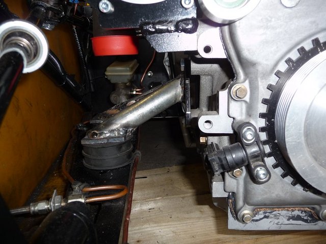
Finished engine mounts 1
Passenger side

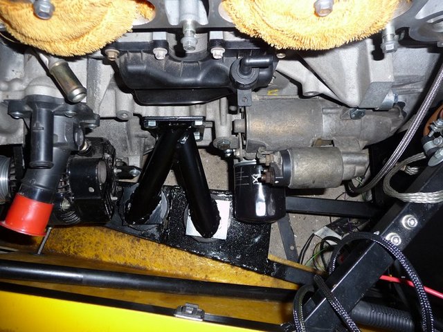
Finished engine mounts 4
Drivers side

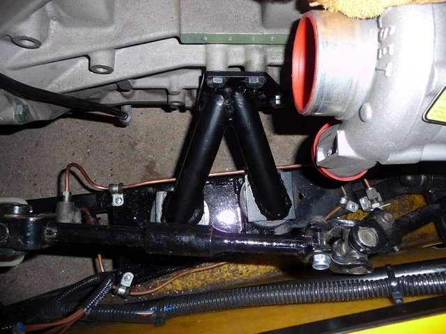
Finished engine mounts 3
The rad and intercooler are finished too and should be here next week 
.JPG)
.JPG)
.JPG)
Next weekends jobs are mounting the oil cooler for the supercharger. Adding in an additional bolt bracket on the supercharger bracket which will
increase the stiffness of the mount considerably. Mounting the swirl pot and header tank. Connecting up the clutch and checking for leaks. Starting to
suss out the wiring and pipework for the engine bay.
Stuart_B - 14/2/10 at 07:23 PM
that looks awesome david,
great work
stuart
goaty - 14/2/10 at 08:36 PM
that does look amazing. cant wait for mine 
flak monkey - 17/2/10 at 09:57 PM
Modded the throttle bodies tonight to give me a point to take a MAP signal from each. Oddly most off the shelf throttle bodies seem to only come with
TPS as standard and no option for map.
Nerve racking drilling into several hundred quids worth of throttle bodies, but there we go...
Fitted an M5 threaded, 4mm hose tail into each port. Sealed in with Loctite 542 thread sealant.
Once modded they were fitted up again, and hopefully wont be coming off again any time soon  Throttle stops all set and locked off too to cosworths
recommended base settings.

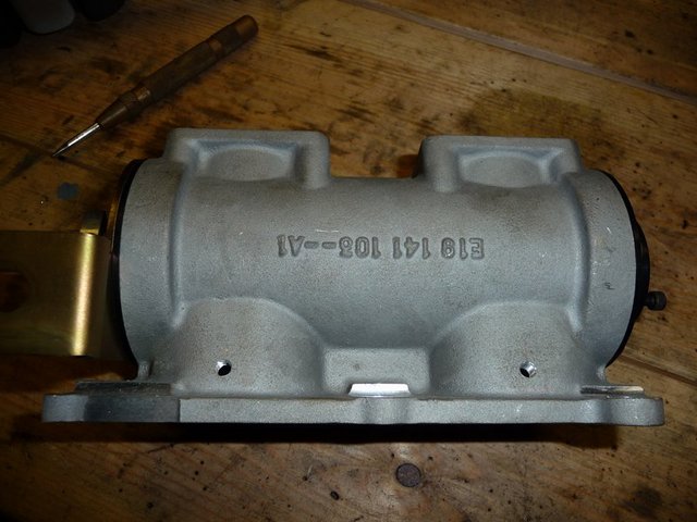
Throttle body mods 1

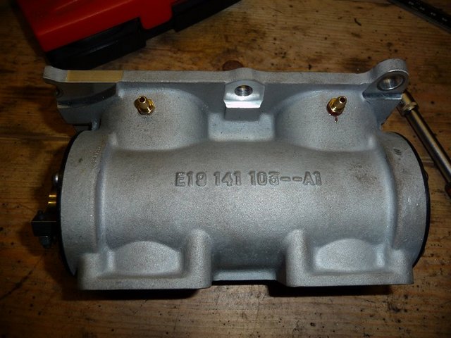
Throttle body mods 2

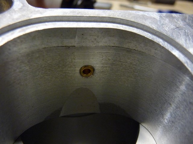
Throttle body mods 3

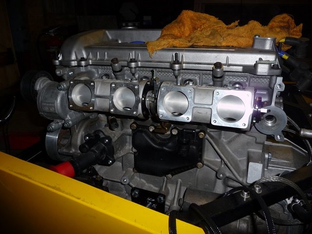
Throttle body mods 14

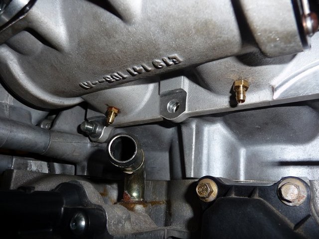
Throttle body mods 5
goaty - 17/2/10 at 10:28 PM
looks briliant, not sure if i woudl be brave enough..lol. Are you going to run them to a little break tank or just tee them straight to the map
sensor??
Some seem to use a little tank to loose any chance of pulses....
wont be long till she runs 

flak monkey - 18/2/10 at 08:53 PM
I will probably run them to a small tank as I need to split the MAP signal between the ECU, fuel pressure regulator and dump valve...
Getting a bit worried about progress at the moment, as I need to get enough time in to get it mapped on the road before stoneleigh otherwise I'll
be in the tintop 
Steve Hignett - 18/2/10 at 08:58 PM
quote:
Originally posted by flak monkeyotherwise I'll be in the tintop 
Don't even think it...
goaty - 18/2/10 at 09:42 PM
lol, i am sure you will make it, unfortunately i am garunteed to be in tin top, bt am awiting a peek at yours 
matt.c - 18/2/10 at 10:35 PM
Great progress flak. Have you thought about fitting a full fire extinguisher system? Wouldnt want a small leak to end in disaster! 
flak monkey - 19/2/10 at 07:52 PM
Made a little more progress this afternoon. Had to come in as its really quite cold and damp outside now 
First job was to add another bit to the supercharger bracket. There was a bolt hole in just the right place, and the mod should stiffen up the bracket
as I was concerned about it twisting should I start to increase boost.
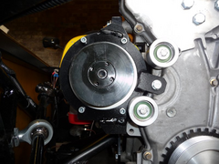

Supercharger mount mod 2
Also got the water outlet fitted after drilling and tapping to fit the water temp thermocouple for the dash. Can start working out the cooling pipe
layout, along with fuel pipe layout etc.

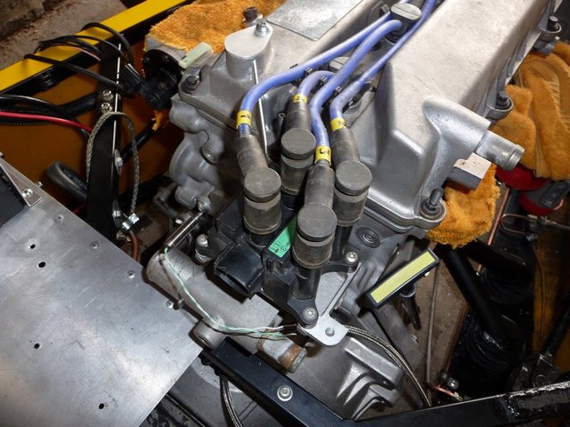
Water outlet and coil
Next started making the mounting brackets for the supercharger oil cooler.
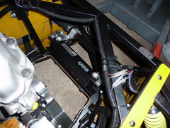

Charger oil cooler 1

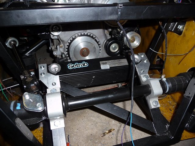
Charger oil cooler 2
Tomorrow I plan to start having a look at the mounts for the rad/intercooler. Then I really need to test out the hydraulic clutch before finally
starting to connect the electrics, cooling and fuel up.
goaty - 20/2/10 at 08:05 AM
looks very good, does look like it will start gettint tight once pipes start going in.
Out of interest, what injectors are you running now? one in the Tb's? any idea on size yet???
I basically trying to work out what power you think you will be seeing now 
now you got the roller barrels on there 
Also, are you going to run an oil cooler for the engine too???
Cheers dave
[Edited on 20/2/10 by goaty]
flak monkey - 20/2/10 at 05:43 PM
New injectors are 60lb/hr (630cc/min) siemens deka's which at std pressure should be enough for around 400bhp, which is more than I am looking
for anyway.
Made some more progress today. Still havent got the clutch tested, but got plenty of other jobs done....
Fitted the fuel rail complete with the new injectors. It did originally foul the idle screw on the throttle bodies, so I had to cut that down. Also
looks like access will be tight to the balance screws, but not impossible 
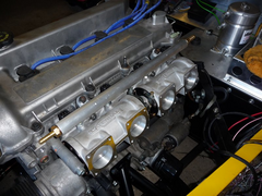

Fuel rail fitted 1
Next job was to test fit the rad/intercooler. I have recycled the old 1.5mm thick stainless brackets I made for the original polo radiator, and just
chopped them about a bit so that they suit the new rad/intercooler. I had to make sure that it was as close to chassis as possible, but still allowing
space for the rad fan behind it as it is so thick there is no room at all to spare in the front.

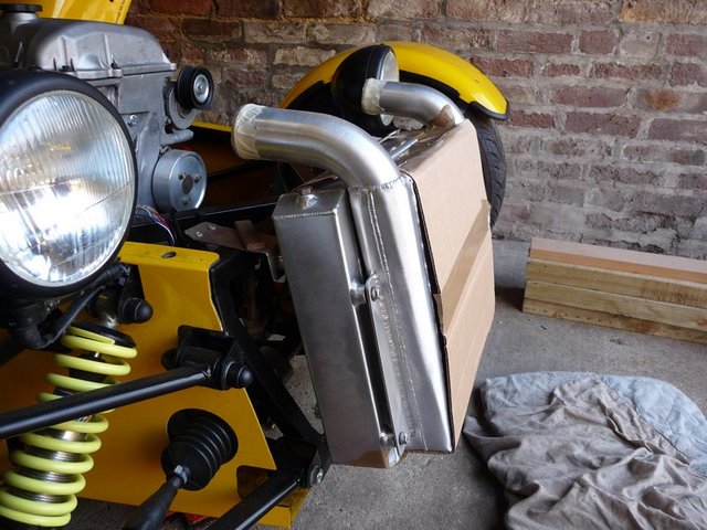
rad fitting 1

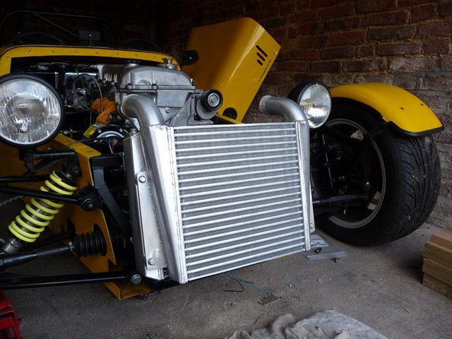
Rad fitting 2
Once I was happy with the position of it, the brackets were riveted to the chassis. And this is how its all ened up. Very happy with the fitment.
Theres 3mm clear to the chassis on the bottom hose, and the same to the intercooler hoses in the nose.

Rad fitting 3

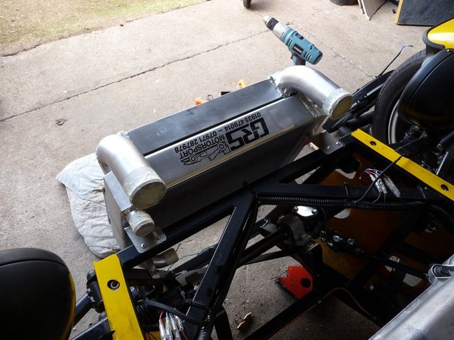
Rad fitting 4

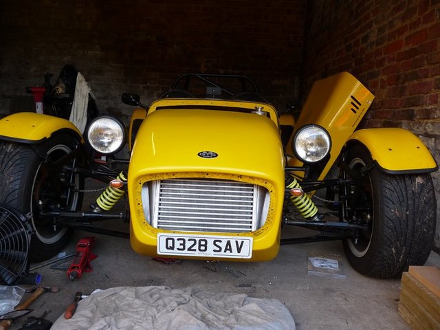
Rad fitting 5

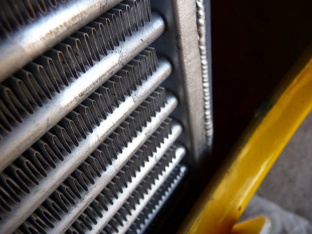
Rad fitting6

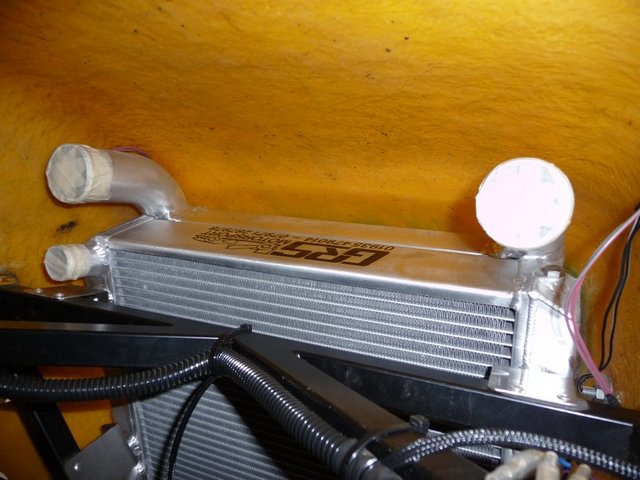
Rad fitting 7
Test fitted the plenum with the spacers too. Looks like I could skim around 5mm off the thick spacer, and maybe 3mm off the middle spacer. This would
mean there would be plenty of clearance between the plenum and the inside of the bonnet and mean nothing sticking out the side of the bonnet.

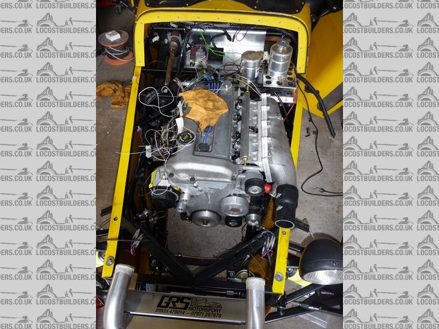
Plenum test fitting 1

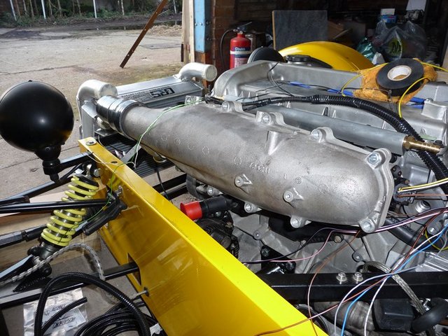
Plenum test fitting 2
Its going to be tight in several places once all the pipe work is in situ, so I am trying to mock as much up as possible now so I can figure out where
everything is going to end up. Spent some time tidying the wiring too, looks like it will all work out ok.
Last job today was to mock up the supercharger to intercooler pipework, and it looks like it will work out as planned.

Intercooler pipe work mock up

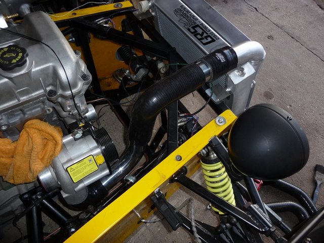
Intercooler pipe work mock up
beaver34 - 20/2/10 at 06:22 PM
looks good, nice short pipework to cooler and looks neat!
goaty - 21/2/10 at 10:50 AM
that looks abosutley amazing, the look of it with all the bits coming together makes it look wicked, really love the pic looking from the front with
the nose sat on.Bet you are really pleased with progress 
Stuart_B - 21/2/10 at 11:14 AM
wow, that is coming on nicely.
i do not think i would have been brave enough to drill those throttle boddies.lol
i am looking foward to seeing this.
keep up the good work david.
stuart
eddie99 - 21/2/10 at 11:30 AM
Stunning as usual... keep it up! Can't wait to see it this summer!
FASTdan - 22/2/10 at 12:57 PM
Looking very nice indeed, custom rad and cooler are bang on! 
Have you got round to looking at fitting the pinto exhaust manifold yet?
We provisionally dropped our dura in over the weekend. I was looking at the manifold and hadnt appreciated the quite big difference in exhaust port
spacing.
I'm just uming and ahing about which way to go. I've got a duratec flange, and my intention was to mod the existing headers to suit, but
just not sure the best way to go about it.....
flak monkey - 22/2/10 at 02:46 PM
Exhaust is on the list of jobs for this weekend.
The middle 2 ports are pretty close (about 5-10mm) the outer 2 are further apart and need a bend welding in to get them to meet up. I reckon some
welding/cutting and a 45deg bend should sort it.
David
goaty - 22/2/10 at 08:00 PM
i see you managed to sort out a tps, what was it off in the end? zetec??
do love the look of the plenum on it, sweps round lovely. 
flak monkey - 22/2/10 at 09:09 PM
The TPS is from a duratec engined mondeo from what I can tell.
Got a new one from cosworth though as it was only £25
Itching to get back out in the garage really....shame the car's 20miles away 
Should be able to test the clutch this week. If all OK then its time to sort the exhaust and finish the rest of the wiring....
goaty - 23/2/10 at 07:17 AM
wont be long till she firing up 

flak monkey - 23/2/10 at 08:25 PM
Well the clutch seems to function (rocking the car backwards and forwards in gear it seems to release with spare travel ok).
Time will tell if there are any leaks anywhere inside the bellhousing.
The master cylinder just needs finally bolting in (could be challenging as access to bolts is tight to say the least!) and the clevis and pedal
setting up properly. Which will be the first job next time I am in the garage.
Then its time to start sorting the plumbing for the radiator and fuelling. Its all going to be very tight, I know that much, and I think I will
probably spend longer staring at the car trying to figure out where everything is going to go!
goaty - 23/2/10 at 10:09 PM
tell me about it, took me 3 hours today standing looking at making engine mounts, got the basis sorted at least, on with 2mo 
just keep plugging, no questioning it will be tight, i got inboard suspension too 
flak monkey - 27/2/10 at 09:12 PM
After the annoyance of having to have the engine out as the clutch cylinder was leaking, things are picking up again I think, though I dont want to
speak too soon!
Spent all afternoon yesterday trying to cure the leak on the concentric slave cylinder. Typically it was the fitting I made that was leaking.
Tightening it up some more seems to have cured the major leak. There was also a secondary leak from the compression fitting on the hose, which I also
think I have now fixed...I'll find out sooner or later I guess!
Today has been spent getting the engine mounted back in the chassis properly making sure all the bellhousing bolts are tight and properly fitting the
clutch master cylinder. Then loads of other little jobs...
Made new battery cables to suit from the more newer, more flexible stuff. Well recommended over the older hard to work with stuff.
Finished off the engine wiring too, just the coil pack to connect up when I can find a suitable connector for it and the VR sensor to connect.
Mocked up the top hose for the cooling too, need another 45 deg bend to bring it all in alignment though.
Started to try and figure out how to layout the fuel system too, as there's not much space. Looks like its all going to fit in there some how
though.
flak monkey - 28/2/10 at 05:27 PM
Finished off a few more bits today.
Found a home for the fuel pump, which keeps it out of the way of all the other piping which has to fit in the same area. Just need to tidy up the
wiring running alongside the battery. But I have yet to run the MAP line for the ECU, alternator charging cable and the starter cable.

Fuelling

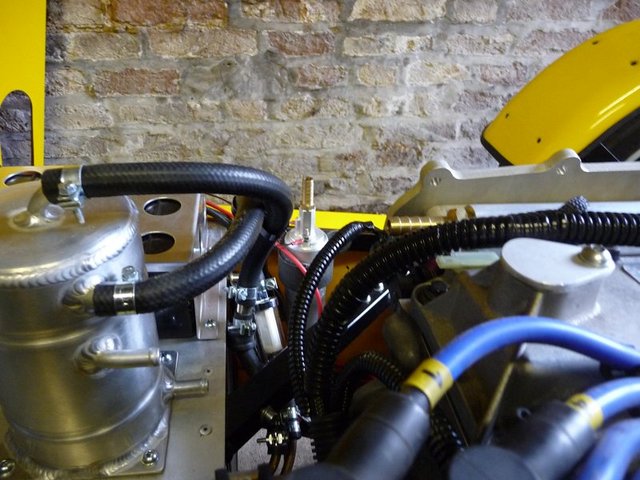
Fuelling 2
This is the mock up of the top hose.

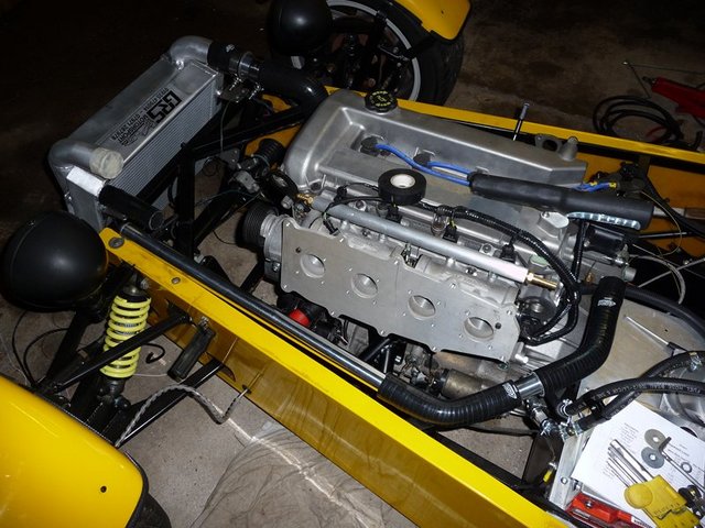
Top hose mock up
Mocked up the bottom hose to the radiator too which looks like it might just fit around everything else....

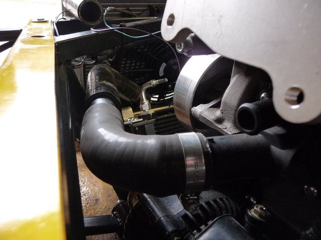
Bottom hose 1

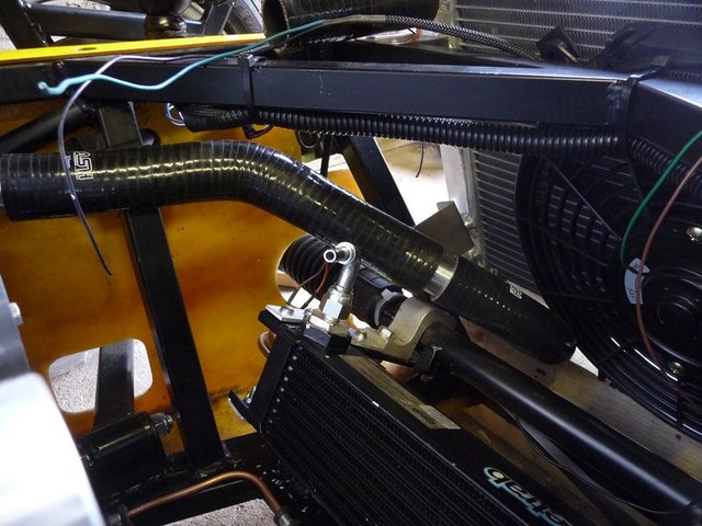
Bottom hose 2
Finally finished the last idler pulley off too, so there is now a full complement of alloy pulleys on the engine.

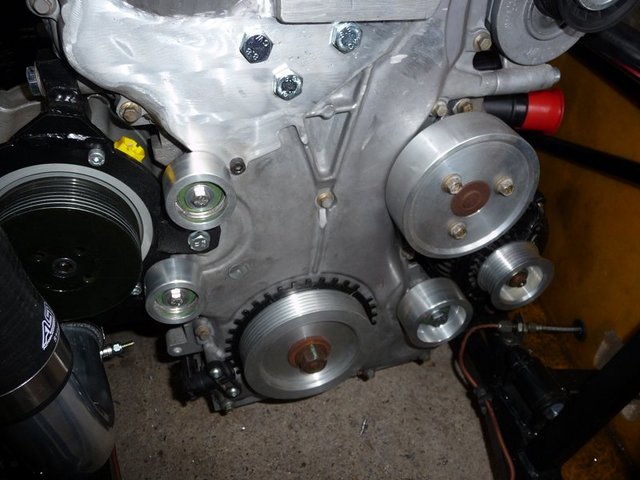
Idlers
[Edited on 28/2/10 by flak monkey]
goaty - 28/2/10 at 06:06 PM
not too far left now 
goaty - 28/2/10 at 07:46 PM
also, on the top of your roller barrel's, what are the what look like bleed screws for??

cheers
and i keep forgetting to ask what spark plugs you have gone for?? not sure which would suit best...lol
[Edited on 28/2/10 by goaty]
flak monkey - 28/2/10 at 08:30 PM
They are bleed screws so you can balance each individual throttle body 
I have just put 1 stage colder plugs in than standard, can't remember what the number is off the top of my head though 
eddie99 - 28/2/10 at 11:40 PM
Keep Plugging away David, You'll be done soon at that rate 

Tim 45 - 1/3/10 at 06:30 PM
David, looking good!
Just reading through some of your posts you keep mentioning you want around 300bhp/300Nm....
What have you done to your gearbox to rate it to that sort of power? I was under the impression that the heaviest duty "off the shelf" kits
were rated to 280bhp/250 Nm(bgh) and 250bhp (quaife)...
With the power that you're getting, I wouldnt have thought the type 9 box is capable in any configuration of the power you're after....
Caterham use their own custom built box, and i'm assuming that had to be uprated for their X330 concept...
I find that given a gearbox upgrade is needed on an install this powerful brings in an added cost that has no real option of DIY...and hence the idea
that an install such as yours can be done on the cheap, is slightly misleading...
[Edited on 2/3/10 by Tim 45]
sebastiaan - 1/3/10 at 08:52 PM
Hi David,
As you've drilled your TB's (and are going to run MS2?), you might want to try the latest version of the MS2 extra code once the engine is
ready to fire up. A change to the MAP sampling has been (finally!) implemented to make sure the MAP is only measured in a certain crank angle degree
window (which you can specify). The code then uses the lowest value measured in that window. This should enable you to run just one MAP line from one
throttlebody and do away with the horrendous map filter / transient detection killer / vacuum manifold that is so often used.
Good luck! ;-)
Sebastiaan
ETA: this topic describes the alorithm in a bit more detail:
http://www.msextra.com/forums/viewtopic.php?f=91&t=31877&hilit=sampling
[Edited on 1/3/10 by sebastiaan]
flak monkey - 6/3/10 at 03:21 PM
Just finished off my exhaust manifold. Took a bit of doing, but I am quite pleased with the results. The welding isnt the neatest, but there we go.
Started off by chopping the old flange off the pinto exhuast, then clamping cyl 2 and 3 runners in the right place using a jubilee clip. The spacing
is about 10mm different between the duratec and pinto.

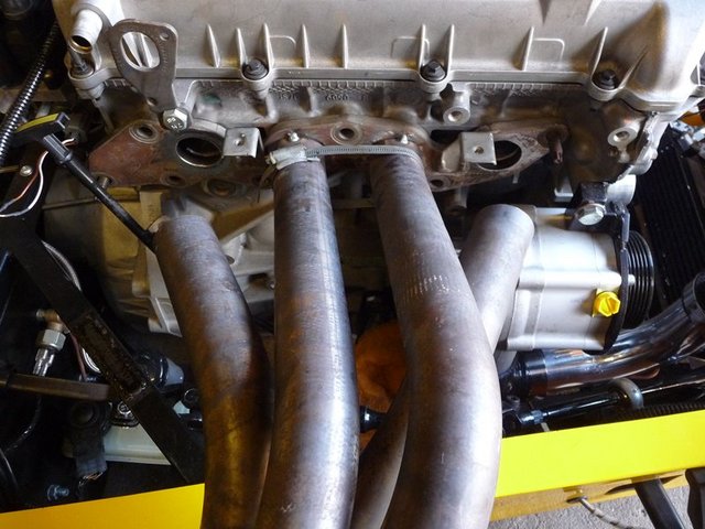
Exhaust 1
Cyl 1 and 4 required more adjustment, and I cut the runners back about 4". The cut and welded 2 mandrel bent 45 deg tubes to suit.

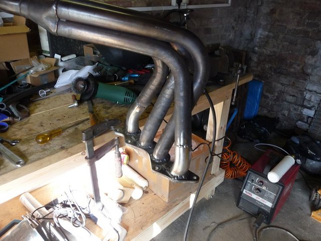
Exhaust 2
Not too worried about the visual appearance of the welds on the runners as they will be covered by exhaust wrap eventually.
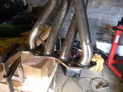

Exhaust 3
And thankfully it all fits ok.
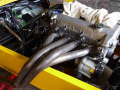

Exhaust 4
And there's plenty of clearance to the supercharger too.

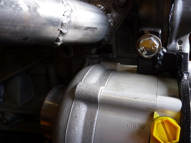
Exhaust 5
Now going to go and sort the link pipe for between the manifold and silencer 
iscmatt - 6/3/10 at 04:47 PM
excellent work on the manifold there, looks very neat, what are the main jobs left on the list before stonleigh? Also, out of interest, what has been
the hardest bit of the conversion so far?
cheers!
flak monkey - 6/3/10 at 06:33 PM
Thanks, its coming on. Theres still quite a bit to do before stoneleigh, though I am hoping to get it running in the next couple of weeks.
I need to get the supercharger oil system finished, rad fan mounted, wiring for the coil and VR sensor, plumbing finally clipped in, rad fan mounted,
fuel system finished, header tank mounted and thats about it for the engine side. After that the whole back end needs to be stripped down so I can
change the diff and fit the discs etc. The suspension all needs repainting too.
Will see how I get on tomorrow, hoping to tidy up a lot of the small odd jobs tomorrow.
Cut the original link pipe to suit so now the exhaust is all sitting as it should
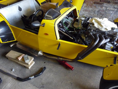

Exhaust finished
Also tidied up the top hose, just needs clipping to finish

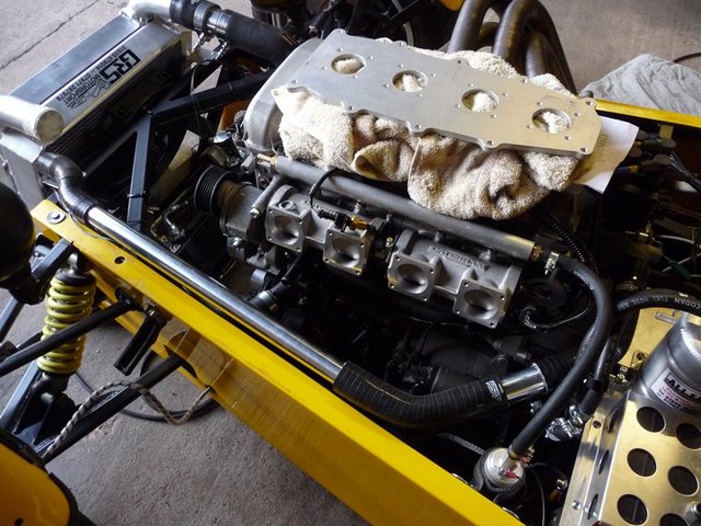
Top hose
Not sure what the trickiest job has been. Nothings been really difficult but there has been a lot of things to work out along the way. Clutch has been
a pain from start to finish...
flak monkey - 6/3/10 at 07:44 PM
quote:
Originally posted by Tim 45
David, looking good!
Just reading through some of your posts you keep mentioning you want around 300bhp/300Nm....
What have you done to your gearbox to rate it to that sort of power? I was under the impression that the heaviest duty "off the shelf" kits
were rated to 280bhp/250 Nm(bgh) and 250bhp (quaife)...
With the power that you're getting, I wouldnt have thought the type 9 box is capable in any configuration of the power you're after....
Caterham use their own custom built box, and i'm assuming that had to be uprated for their X330 concept...
I find that given a gearbox upgrade is needed on an install this powerful brings in an added cost that has no real option of DIY...and hence the idea
that an install such as yours can be done on the cheap, is slightly misleading...
Sorry Tim, missed this one for some reason...
I have fitted a heavy duty BGH box to mine. Which is rated to 200lbft, their top of the range will handle 250lbft (340Nm) which is more than enough. I
know of more than one person running 300+bhp on turbo cars with bog standard type 9s and they hold up amazingly well. The lightweight of the locosts
seem to help and I dont intend to drag race or do regular track days, or fit slicks so with the amount of force the box is seeing it should be just
fine.
The other option would have been to fit a T5 from the outset, but I went too far down the line with the T9 to go for the T5 now unless I have major
problems.
The quaife sequential box that caterham use has had no end of problems and are a rediculous price.
To be honest I am more worried about trashing the diff than the gearbox 
beaver34 - 6/3/10 at 08:16 PM
box should be fine i would think, naff all weight anyway, what rear diff is it?
flak monkey - 7/3/10 at 08:04 PM
quote:
Originally posted by beaver34
box should be fine i would think, naff all weight anyway, what rear diff is it?
Standard Sierra 3.62 7" LSD in the back
Not much progress at the moment, connecting up the last of the ancilaries.
Spent all afternoon trying to decide how to mount the rad fan, then gave up and fitted it using the through the rad ties. Thankfully it seems to work
from the switch properly, just need to see if it auto switches from the MS.
Not many jobs left before the start up.
flak monkey - 12/3/10 at 09:00 PM
If everything goes to plan I am going to try and get the car started tomorrow.
Got much of the to do list done just a few odd things to finish off: running the fuel return line after temp mounting the FPR somewhere out of the
way.
This is the current state of things, got the supercharger oil lines in last night and a few other odds tidied up, still need to clip in the hoses
though:

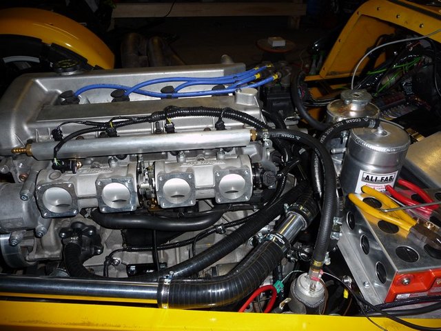


Cranked the engine over for the first time tonight, seem to be getting good oil pressure (40psi on cranking) and after puzzling for 10 mins as to why
I didnt have a stable cranking signal I remembered that I hadnt adjusted the VR sensor pots in the ECU, now all sorted.
Oncce the fuel lines are finished I can pump fuel around and check for leaks then give it a crank and see what happens.....
eddie99 - 12/3/10 at 09:06 PM
Looks excellent, can't wait to see the first start up video posted tomorrow evening 
Madinventions - 12/3/10 at 11:22 PM
Fingers crossed...
I bet it fires up first time!

iscmatt - 13/3/10 at 12:34 AM
wahey, i cant wait for the video! fingers crossed for you!
sebastiaan - 13/3/10 at 08:22 AM
Good stuff!
Would it be possible to fit a simple (ali?) heatshield below the exhaust manifold? I see you've sleeved a number of hoses (looks like they are
the oil supply hoses from the reservoir to the S/C?), but some more heat protection might be usefull. Last thing you want is hot oil meeting a hot
manifold. That'd be game over for the car....


Something like a horizontal plate just below the primaries would do.
scootz - 13/3/10 at 01:09 PM
Looking good!
flak monkey - 20/3/10 at 08:47 PM
I better keep this thread up to date with all the latest so its referenced. Not going to repeat anything but...
Engine fired up first time with no major problems other than a very high idle. Some videos etc can be found here:
http://www.youtube.com/watch?v=xpQ2BYMFO7s
http://www.youtube.com/watch?v=j5T9Cj8Q0EQ
This then led to a week of trying to find out what was causing the high idle. No Vac leaks could be identified anywhere, the whole assembly was
removed, checked and reassembled several times with no improvement.
http://www.locostbuilders.co.uk/viewthread.php?tid=131856
http://locostbuilders.co.uk/viewthread.php?tid=131973
http://locostbuilders.co.uk/viewthread.php?tid=132212&page=1
I spoke to several knowledgeable people during the week, including several experienced in setting up Roller Barrel throttle bodies and the general
consensus was the same - high idle is a common problem with rollers and seems more apparent on some engines than others. Theres not really a fix to
it, and its something you just have to live with if you have it.
I made the decision to switch to Jenvey DTH throttle bodies to solve the problem and thankfully it did. It idles much better and I found Raceline to
be incredibly helpful and genuinely interested in the project.
Some piccies of the Jenveys

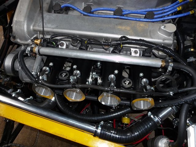
Jenveys 1
And made a set of MAP take offs to fit in the injector ports. Sealed with Hylomar and then clamped in with some fabricated brackets. They have been
painted now and are drying overnight before final fitting tomorrow morning.

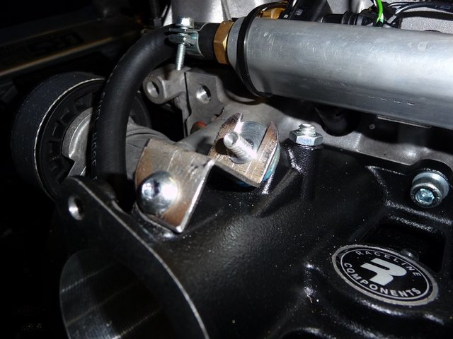
Jenvey MAP mod 1
goaty - 20/3/10 at 11:05 PM
look very smart, do like the map take offs 
flak monkey - 27/3/10 at 08:16 PM
Nearly there...
Fitted up the plenum backplate yesterday. Many thanks to Boggle the rapid turn around on the cutting!
That allowed me to get a bracket made up for the throttle cable which bolts to the back of the plate.
This morning got it all fitted up, albeit temporarily as it has to come off to change the starter as it seems to randomly decide not to engage about
50% of the time  Another is on order and will hopefully arrive during the week.

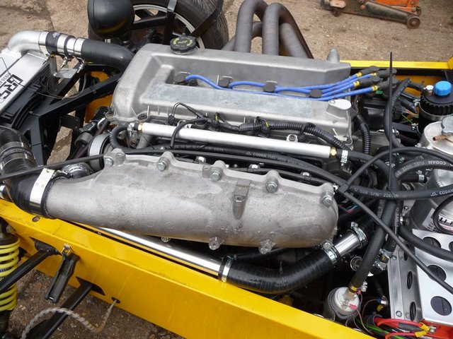
Plenum fitted 1

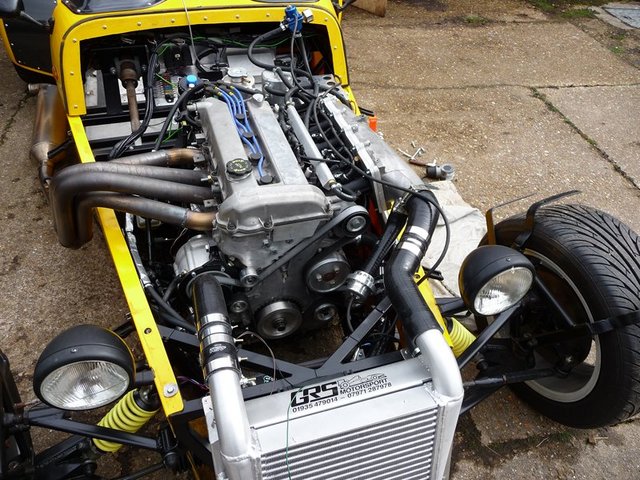
Plenum fitted 2

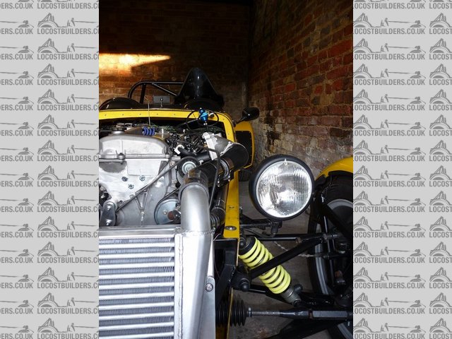
Plenum fitted 4
You can see that I am going to have to have a substantial hole in the side of the bonnet now in order to clear the plenum pipework. Nevermind, its a
price worth paying to get a smoother running engine.
The other main job for today was making the idler stiffening plate for the 2 small idlers either side of the supercharger. Because they are only on M6
bolts and seemed to flex quite considerably with a bit of force by hand I decided to link them together then bolt them back to the block using the M8
bolt which is between them.
I know the plate is a little overkill on the thickness, but its what was laying around....

Idler stiffening plate 1

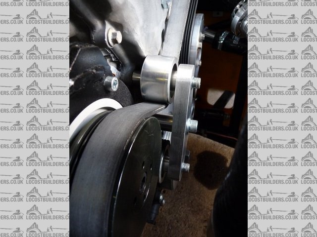
Idler stiffening plate 2
Hopefully that will keep it all in check 
Final job of the day was to re-attach the front wings. Something I have been putting off for a while.

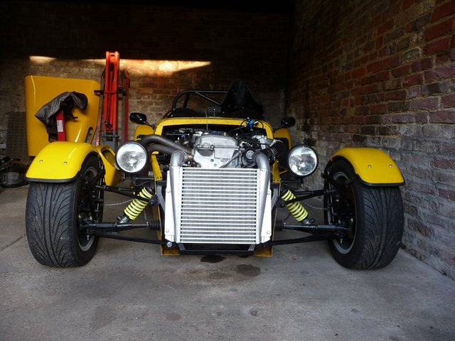
Getting there
Insurance docs came through today so hoping to get tax sorted next week and get back on the road for next weekend....
Be prepared for the bad weather to ensue!
Last jobs are some tidying up of pipes and cabling. Moving the dump valve to the outlet of the intercooler and blanking off the oulet on the plenum
(its too close to the top hose now). Finishing a few odd bits of wiring and putting more P-clips down (though I ran out of cable ties today!
Tragic!). I also have to find an airfilter to fit a bit better than the one I currenty have....
Finally, I took another short vid today with it running with everything connected up properly. Forgot to turn wind cut off on the camera though so
the sounds all screwed up again.... 
http://www.youtube.com/watch?v=Jg3CLG9Z3Dc
westy turbo - 28/3/10 at 06:27 AM
Had the same issue on my westie as far as the inlet-bonnet and had to alter the angle 2 times to sorted out..dont worrie if it sticks out a bit,mad
max look your set up looks ace!
thats before

[Edited on 28/3/10 by westy turbo]
[Edited on 28/3/10 by westy turbo]
[Edited on 28/3/10 by westy turbo]
[Edited on 28/3/10 by westy turbo]
westy turbo - 28/3/10 at 07:00 AM
and thats the after

flak monkey - 28/3/10 at 08:08 AM
Yep the intention now is to leave it as is, then later in the year have a bulge made to cover it all up which is stuck on from the inside of the
nose/bonnet 
David
goaty - 28/3/10 at 11:21 AM
Dave,
that is awesome, cant believe how it all fits in, minor for the plenum though. I love it, the brace on the idlers looks perfect too, bet our over the
moon now 

Xtreme Kermit - 29/3/10 at 07:05 PM
looks fantastic!
What are you using for an injection map?
flak monkey - 29/3/10 at 07:17 PM
Injection map is one I made myself, followed the theory on ignition timing which will hopefully get it somewhere close.
Need to get driving it now though so I can get it set up to a reasonable level before the 200mile round trip to Stoneleigh 
Stuart_B - 30/3/10 at 05:27 PM
nice one david.
it runs lovely from the sound.
stuart
flak monkey - 30/3/10 at 07:42 PM
Coming on. Got the last of the bits through today.
Replaced the starter as the orginal didnt engage 70% of the time and was annoying. Replaced with a low milage Fiesta ST one and all seems to be good
now.
Getting this fitted allowed me to get the plenum all fitted up finally. Its been on and off a few times, but now (hopefully) its on to stay....
The trumpets are very short - around 15mm from the backplate face.

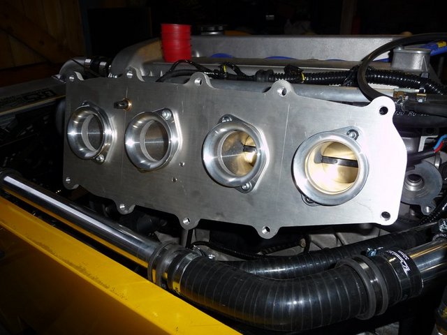
Plenum plate fitted final
After that, the final fitting of the intercooler hoses and dump valve. I have since run the vac line to the valve properly... I had to move the dump
valve from the plenum as there is just not enough room to get a pipe on the take off due to the position of the top hose. If I had run it under the
chassis at the front it would have been ok.

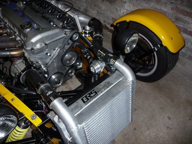
Final intercooler hoses 1

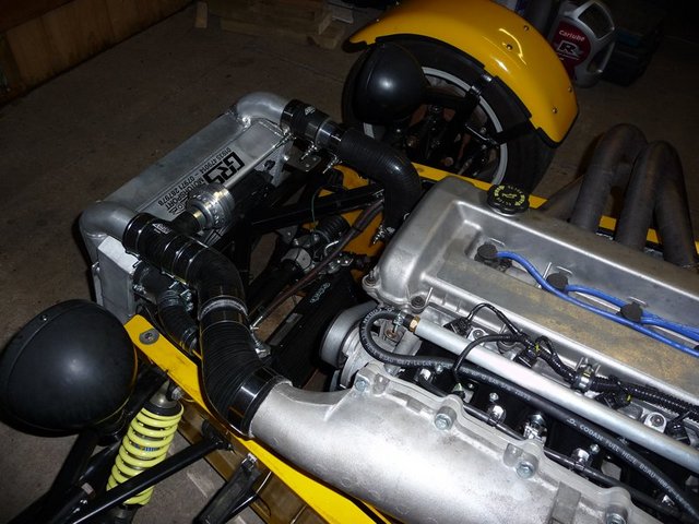
Final intercooler hoses 2
All runs ok, still need to get warm up enrichments sorted as its a little lean when cold.
Next job is to get the interior panels back as I now have the bolts for the propshaft. Shouldnt take to long to get it all back in order. Top tunnel
panel needs modifying for new gearstick position amongst a few other things 
goaty - 31/3/10 at 04:44 PM
lol, just found them as you replied, they do make it look very nice.
you really cant be far away froma drive now surely....
flak monkey - 31/3/10 at 04:46 PM
Should be out for a drive this weekend if I can get tax sorted and the weather is reasonable
flak monkey - 2/4/10 at 07:13 PM
Another busy day today.
First job was getting the air filter fitted. Piped to the back of the supercharger using aluminium tubes and silicone hose, then mounted on top of the
drivers footwell. Planning to put vents in the side of the bonnet anyway, so hopefully will get enough cold air in there.
Still have to wrap the exhaust, which is a job I keep putting off as its a messy job!
Next finished cable tying all the loose cables and pipes behind the scuttle, then modified the firewall and got it refitted.
Had some worrying blue smoke when the engine was running earlier, accompanied with some oil leaking around cyl 4 exhaust port which was rather
strange. Been fine ever since though (been running for an hour or so since without a problem). So will have to keep an eye on that...
Seem to have got the cold start nearly sorted too. Flooded the engine when trying to start first thing this morning so it was only running on 2
cylinders. Seems to be much better now.

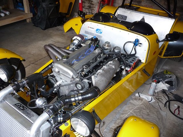
Nearly finished 1

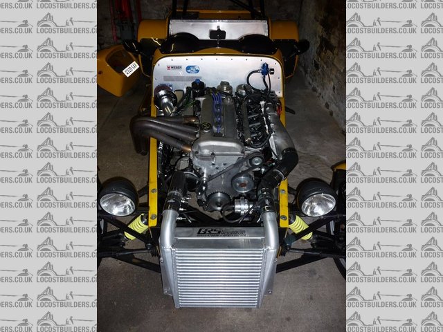
Nearly finished 2

Nearly finished 3
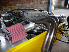

Filter fitted 3
[Edited on 2/4/10 by flak monkey]
flak monkey - 2/4/10 at 07:41 PM
And finally a video with decent sound....
http://www.youtube.com/watch?v=nRt-oz8gI04
boggle - 3/4/10 at 02:51 PM
looking good mate...
that plenium back plate looks nice 
flak monkey - 3/4/10 at 07:53 PM
Yep, spot on thanks mate 
Finished off the bodywork today. Cut lots of card templates then made lots of yellow dust 
Pretty happy with the results. Just need to make a box inside the bonnet for the filter and refit the interior and wrap the exhaust now and its ready
for a drive 

New bonnet fitted 1

New bonnet fitted 3

New bonnet fitted 4

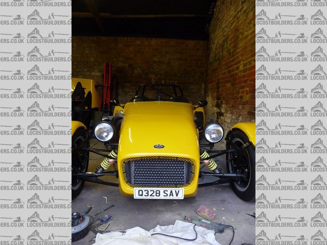
New bonnet fitted 2
scootz - 3/4/10 at 08:23 PM
Looks really good David!
eddie99 - 3/4/10 at 10:41 PM
Looks stunning! Well done mate, you should be chuffed!
Stuart_B - 4/4/10 at 10:06 AM
that bonnet air holes look cool, i realy do like the 3 angled ones at the back, i would have never of throught about them.
stuart
dlatch - 4/4/10 at 11:27 AM
david where did you get the cutdown number plate?
bonnet mods look great by the way 
flak monkey - 29/4/10 at 02:58 PM
I am sure most are aware of the minor problems I have been having since getting the car on the road.
The car is now running on Omex engine management rather than Megasquirt as it randomly decided to start playing up last weekend and I have yet to find
the problem. It was fired into life for the first time on Omex last night and seems to work reasonably well considering the map is a long way out. The
final thing is to re-cover all the wiring again and to change the coolant temp sensor as the standard Duratec one doesnt seem to suit the bias
resistors in the Omex ecu very well giving very poor resolution at lower coolant temps.
I have another smaller supercharger pulley on order, 85mm dia which should bring the boost up to just under 15psi (1bar) which is where I had wanted
it to be.
The car is then booked in to be set up at ATSpeed Racing on May 17th. Fingers crossed everything will be ok for this session.
Other minor problems are I have a gearbox oil leak from somewhere. I need to pull the covers off the transmission tunnel to try and figure out where
it is leaking from. Its a couple of drips per day - I just hope its nothing too serious. But no doubt will require the engine to come out to resolve
it in the long term.
Sump leaks are all fixed all bar a very minor weep at the front. If the engine is out at any point then I will weld it up properly.
Other than that - its quick, and still driveable right down to 1500rpm in 5th. It will be very interesting to see what power it makes on the rollers
next month!

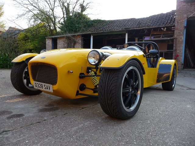
Front pass 1
NS Dev - 29/4/10 at 07:21 PM
looking like a good job David!
Nice work.
Is that plenum a nissan gti r one? Looking into using one on a vauxhall at the mo, look nice and adaptable!
flak monkey - 29/4/10 at 10:05 PM
Thanks Nat 
Yes it is a nissan GTiR one, actually relatively cheap to pick up as well. Mine cost about £50.
David
flak monkey - 1/5/10 at 06:36 PM
Posting sitting at stoneleigh.
Took the car for its first drive since changing to Omex this morning, works suprisingly well considering its a base map. Richened a few sites up a bit
and it cruises fine now so all reeady for a rolling road set up from that side of things.
Now i just need to find the source of my gearbox oil leak. There's always something!
NS Dev - 1/5/10 at 09:16 PM
gearbox leak, where from? if its the front, between box and bellhousing then it'll be leaking around the selector shaft.
flak monkey - 2/5/10 at 09:38 PM
I thought it was leaking from around the sandwich plate/tail housing but it all looks good.
Drips congreate on that area and on the bolts holding the gearbox mount to the chassis. There is now also oil seeping through to the passenger
footwell, so its obviously getting flung up from somewhere.
It was rebuilt with all new seals and gaskets which is the most annoying bit about it.
Grrr 
flak monkey - 3/5/10 at 03:16 PM
Well after removing the tunnel top this morning I think I found the main gearbox leak. Appeared to be leaking around the 5th ear adjuster plate on the
side. Even though I had put sealant round it once before. That'll teach me not to use hylomar!
Time will tell, took it for a short run this afternoon and got it hot, so it'll just have to stand now and I'll see if its still leaking.
flak monkey - 1/10/10 at 01:27 PM
Had the GTS on the rolling road again today after changing the cams for Raceline 210 spec ones.
Took it to Northampton Motorsport this time and Troy there gets a very good recommendation from me. Very friendly, thorough, and has made an
exceptional job of the mapping. The car is now better than it has ever been.
The result was:

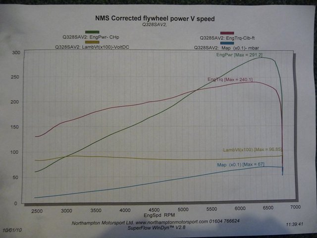
01-10-10 dyno result
291.2bhp @6,456rpm and 240.1lbft @6,333rpm at the flywheel. Which translates to 273.3bhp and 226.2lbft at the wheels.
With 190lbft from 4000rpm up its certainly fun in the wet!
Boost dropped from 12psi with standard cams, to 10psi with the mild road cams. So there is scope for more power with more boost if you want to get
silly.
David
Nitrogeno25 - 9/3/11 at 04:39 PM
quote:
Originally posted by sebastiaan
Good stuff!
Would it be possible to fit a simple (ali?) heatshield below the exhaust manifold? I see you've sleeved a number of hoses (looks like they are
the oil supply hoses from the reservoir to the S/C?), but some more heat protection might be usefull. Last thing you want is hot oil meeting a hot
manifold. That'd be game over for the car....


Something like a horizontal plate just below the primaries would do.
I read a long time ago that the exahust pipes should be arranged according to the firing order which is 1-3-4-2, do you know what effects have doing
it other way?
Thanks and congrats on your build!
purdy - 5/12/11 at 09:25 PM
Hi
Have you come across the oil filter problem yet?
Purdy
Nitrogeno25 - 29/12/11 at 03:59 PM
quote:
Originally posted by flak monkey


Flak, which spark plugs wire are you using with the duratec? I can't find wires with suitable length!
Thank you very much!
flak monkey - 30/1/12 at 12:44 PM
Those were Magnecor wires. 
You need the raceline oil filter adaptor as well, or use a remote filter.
mikey p - 19/7/12 at 08:58 AM
Which bell housing does this use?
the one from RWD Motorsport or titan ect?
floaty - 24/5/13 at 07:08 AM
What about running a sierra cosworth clutch kit.
Vedde - 26/7/15 at 08:37 PM
quote:
Originally posted by flak monkey
Another busy day today.
Took the crank down to Scholar Engines in near Stowmarket to get the crank keyed. Top job and turned it around in 2 hours for me as well! So I was
home just after lunch.


Keyed crank


keyed pulley and gear
Cleaned it all up and fitted to the block. Torqued up the ARP main studs then fitted the conrods to the crank, again with ARP bolts.


Crank and rods refitted
Then fitted the gear to the crank and the oil pump and fitted the modified oil pick up pipe.


Oil pump drive
I also nearly finished modifying the chain cover. The engine mount is redundant and possibly in the way of the belt so I cut it off with the grinder.
Still need to tidy it up a bit, then probably paint the cover to tidy it up, though I may not.
This is the std front cover with the fwd engine mount


Std front cover
And this is the same cover with the mount removed


Modded front cover
I will make some bungs for the old bolt holes too as they arent required any more either. Or I could counterbore the holes and fit cap heads. Not
really decided yet!
Hi Flak
Can the key sit anywhere on the crank's 360 degrees? Or is there a special place where it goes?
baldthreads - 21/10/15 at 01:21 PM
love your work and build very entertaining
PSJ282 - 17/10/16 at 09:15 PM
hi just read your whole thread great work.
i saw at the beginning you said it would be a budget build did you keep track in the end of the overall cost?
ed
Ben_Copeland - 18/10/16 at 04:28 AM
Flak no longer visits this forum unfortunately
selrahc360 - 24/10/17 at 01:10 AM
Just a question why not the miata 6spd they supposedly just bolt up direct to the duratec. I am using a Zetec and was using a t5 and a special bell.
just sold everything and bought a RX8 trans and adapter it put me way ahead on budget and build.
Best,
Charles from the USA.
flak monkey - 24/10/17 at 05:12 AM
When I did this build the 6 speed, Duratec compatible MX5/Miata transmission wasn't readily available.
It also leans the engine over a few degrees which causes issues, and it's a large case, which causes clearance issues compared to the type 9.
selrahc360 - 24/10/17 at 05:08 PM
Flak,
Thank you for the reply. On the 6 spd, the reason I went zetec rx8 6 spd was the bell is a lot smaller than the miata and T5. Also the cost is better
for me. A couple of things I am considering is dual fuel. Though I am currently running cycle carbs. And by dual fuel one or the other, still looking
how to do the swap on the tanks. Although I could do sna
Pin LPG bottles.
Do you have any ideas along those lines. CNG and LPG work way better if the car is stored for any length of time.
How do you like the duratec after running it for several years ?
I have the 2.5 in our transit connect van with the dual clutch std. Pretty snappy.
Thank you for your response,
Charles
goaty - 27/10/17 at 03:11 PM
quote:
Originally posted by flak monkey
When I did this build the 6 speed, Duratec compatible MX5/Miata transmission wasn't readily available.
It also leans the engine over a few degrees which causes issues, and it's a large case, which causes clearance issues compared to the type 9.
Hey flak.
How are you doing, long time no speak.
Not sure if you remember but I was building my duratec along with yours, unfortunately mine had to be broken to buy a house.
I am now back in a kit though but bike engined.
Good to see your still sharing you knowledge on here
flak monkey - 27/10/17 at 09:48 PM
quote:
Originally posted by goaty
Hey flak.
How are you doing, long time no speak.
Not sure if you remember but I was building my duratec along with yours, unfortunately mine had to be broken to buy a house.
I am now back in a kit though but bike engined.
Good to see your still sharing you knowledge on here
I'm good thanks  back in action after a break of a few years!
I do remember, sorry to hear you had to abandon. Hopefully you've managed to find another project?
I'm probably going to have a sell up myself to sort some finances and a few other things 
goaty - 28/10/17 at 08:15 AM
I couldn't stay away myself...lol
Got a Bec Indy r right now but just taken a deposit on it and bought another charged Bec. Can't wait to start fiddling again.
Do you still own your duratec car?
flak monkey - 28/10/17 at 03:06 PM
No I sold it over 6 years ago. I have my Camaro and bike to keep me busy. But might sell up again soon and start something else. Or just have a break.
Fcck2000 - 27/7/23 at 11:47 AM
quote:
Originally posted by goaty
possible, i have just picked my Titan one up but i think iwill be able to squeeze it all in. Tank is the main issue i think.
Luckily the bloke i bought it off works for Caterham developments team and this is the same things he does. Bought an ap friction plate for £40 too.
But he said get in touch whenever for help as they just made one and got 330bhp.
So it can fit and shoudl go well 
Will be interesting to see how the different builds turn out....cant wait.
all the best
ps, he said that they haven't had any oil pump failures as yet though.
When buying my sump from Raceline for my 2ltr MZR engine I was told the MZR engine has a different (larger) oil pump compared to the Duratec Ford
version. Maybe if the MZR one fits it could be a cheap upgrade to the standard Ford option.
Fcck2000 - 27/7/23 at 11:54 AM
quote:
Originally posted by flak monkey
Starters are the same. Some 1.8s still have a dual mass flywheel.
I'll have a look at mine and get the part number off it, if you then go into a ford dealer they will be able to tell you what models it was
fitted to exactly.
David
I have a lightweight 3.6kg flywheel and matching starter motor for sale.
I removed them from my 2ltr MZR engine that was mated to a RWD internal hydraulic slave and a type 9 gearbox. Only selling because I had issues with
the Type 9 so decided to go with a mazda N7 5 speed. I think it runs with a standard Pinto type clutch.


