flak monkey
|
| posted on 7/12/06 at 06:51 PM |

|
|
Consider adding in two triangulated sections behind the seats. So the seat back is almost part of the chassis. The main problem with open topped cars
is the cabin is a big open and poorly triangulated box which significantly affects chassis stiffness. If you can add in a 'seat brace' it
should increase the stiffness considerably.
Its difficult to explain, but hopefully you know what I mean.
Also if you want to save weight, make the chassis out of round instead of sqaure tube, and keep all of the tube thicknesses down to 18g or 1.25mm.
I would make the roll hoop out of 50mm x 2mm tube. Inch tube really isnt enough, and doesnt look right either.
Your design has no triangulation at all at the moment. It will have a terrible torsional stiffness. Add single cross braces to each rectangular/square
in the chassis.
Nothing personal, but it might be worth reading up on tubular structures and chassis design. There are lots of books available.
Also have you designed your suspension yet? You really need this designed before you can design the chassis. the chassis should just joint up all the
mounting points you need for all of your running gear. At the moment it looks like the sides of your chassis at the front are vertical, this will mean
you will be running equal length wishbones on the front of the car (or near enough) when it is common practice to use unequal length, non-parallel
wishbones up front to give you better handling chracteristics.
David
[Edited on 7/12/06 by flak monkey]
Sera
http://www.motosera.com
|
|
|
|
|
Alan B
|
| posted on 7/12/06 at 06:51 PM |
|
|
quote:
Originally posted by Anman
Another update, although there doesnt seem to be much interest in my efforts.
Increased the length and width to accomodate the passengers and added a rollbar.
Please don't take this the wrong way...I think a lot of people get a little blase with seeing a lot of CAD modelled images and I'm sure
you will get a lot more feedback once you start to cut some actual metal.
Also, you will get more response in the mid-engine section.....mostly the folk in this section already have a plan in mind (sort of) and discuss more
practical aspects like construction etc. rather than design theory.
See you over there.
Alan
|
|
|
Anman
|
| posted on 14/1/07 at 12:22 PM |
|
|
Hi,
Well i toke the advice given by people here and decided to read some books first. I have read chassis by herb adams, im working on the automotive
chassis engineering principles and plan on reading race car vehicle dynamics next.
I have also made some rough suspension designs on paper.
Unfortunately at the moment it itsnt possible for me to buy a donor vehicle and start making really detailed designs. Non the less i couldnt resist to
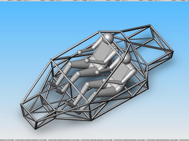
design a few chassis just for the fun of it, but keeping my basic suspension designs in mind. Here are some pics of my latest wip. This design weighs
86 kg, is that a nice weight or is it to heavy?
Thanks
Anne
PS can i post multiple pictures in one post?
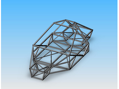 
Rescued attachment d1.jpg
|
|
|
Anman
|
| posted on 14/1/07 at 12:23 PM |
|
|
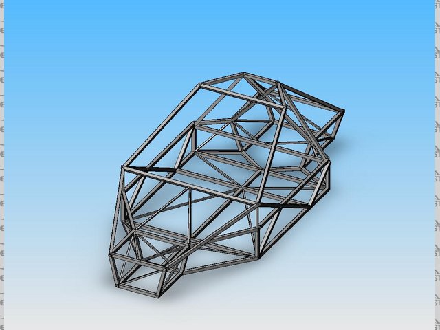
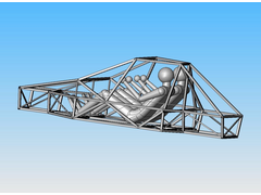
Side view:
Rescued attachment d2.jpg
|
|
|
Anman
|
| posted on 14/1/07 at 12:25 PM |
|
|
And with passengers, might need a little more space for the feet:
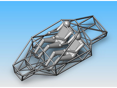 
Rescued attachment d5.jpg
|
|
|
Dick Bear
|
| posted on 14/1/07 at 02:19 PM |
|
|
Howdy Anman,
Your drawings are interesting and they make your ideas for designing a chassis easy to understand. Good work on the graphics!
I'm by no means an expert and not passing judgement on the frame as a whole 'cause there are others who have design/fab the locost frame
and know every angle, length and purpose for each piece by heart and therefore are more qualified to comment on the structure as a whole. But looking
at your last drawing I am struck by the fact that the bars above the heads of the occupants have an unsupported weld seam. If you are planning for
this to be your roll bar solution I question its' effectiveness as drawn. You might want to revisit that area so that if the need for those
protective bars are ever called into service you have a system capable of protecting the driver and a passenger. I fear what may happen now in a
turn-over situation will be more distructive to all than not having anything at all.
The great thing about drawing any system first is the ability to anticipate the forces prior to experiencing them. You are to be commended on your
efforts to do so and your eventual build will be far better because of it.
Thanks for sharing your ideas.
Dick Bear
www.marketpointproductions.com
|
|
|
Anman
|
| posted on 14/1/07 at 02:52 PM |
|
|
Thanks for your reply. You were absolutely right about the rollbar, although i didnt think about it that way, more of a way to increase rigidity.
I have changed the roof and added a support beam. Unfortunatley it is starting to look a bit like a tractor
Rescued attachment d6.jpg
|
|
|
Anman
|
| posted on 13/2/07 at 07:14 PM |
|
|
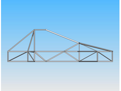
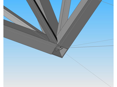
I am having some difficulty with trimming the weldments shown in the picture below.
Any suggestions? I am using solidworks 2006 office.
Rescued attachment i.jpg
|
|
|
cymtriks
|
| posted on 17/2/07 at 09:28 AM |
|
|
quote:
Originally posted by Anman
Another question i have i regarding FEA calculations.
I was wondering which programs you guys use. I have a licensed version of Ansys 9, although i dont like that program. How do you model your chassis
and how do you measure important charaterisitics (eg where are the constraints and loads)?
thanks
I model my designs in Nastran.
I use the following restraints-
a vertical restraint on both rear spring mounts
a lateral and longitudinal restraint at centre between the rear spring mounts
a lateral and vertical restraint at the centre at the front
I use the following loads-
a vertical load on each front spring mount, one side up the other down.
The load is calculated so that 1000ftlbs per degree gives 1 inch of displacement so half that displacement gives 2000ftlbs etc.
My models use one beam element per length of tube (joint to joint). There is no need to use any more elements than this unless you want to look at non
linear (crash simulation) or vibration.
A simple model is always easier to change which is very handy for a home build.
I do not use automesh, I write the decks by hand. This means that I can number all of the elements and nodes in a way that makes sense to me. i.e. the
suspension mounts on one side could be 101 and 102 while the opposite side could be 201 and 202. The tubes could be 100+ for one side, 200+ for the
other with lateral tubes being 300+ etc. I can also use this with materials so that all ally panels are 400+ while steel ones are 500+.
Nastran gives all the element loads in a list in the f06 output file so you can easily look up which tubes are the most highly stressed using a
numbering system like the one above.
[Edited on 18/2/07 by cymtriks]
|
|
|
Chr!S
|
| posted on 21/2/07 at 09:58 PM |
|
|
SolidWorks Modelling
Hi anman! I too am building and designing a locost using SolidWorks. One thing I will say is that joint does look a bit busy!
In solidworks make it all as one part file, and DONT intersect things. You have to be clever and sketch the actual profiles it would make at the joint
and loft them from end to end. Most of the time you can get away with extrusion.
An example would be say if you had a 90 degree tube joint and wanted to add in a triangulation bar at 45 degrees into the joint. I found it much
better to do a 3d sketch of the contact surface and extrude / loft as appropriate. In general just try not to assume solidworks will intersect things
for you. Also if you build the model accurately you can use the SolidWorks plugins to perform FEA/FV solutions. If you want to improve the design
ignore FEA and think simple. Triangular truss structures are strong and light - a simple visual analysis would be far quicker.
If you keep getting the "zero thickness" error (which is not really an error) untick the merge parts box and then merge all the bodies at
the end.
I have a +4 locost SLDPRT file somewhere...
Chr!S
|
|
|
BlackSheep
|
| posted on 22/2/07 at 12:46 PM |
|
|
quote:
Originally posted by Anman
I am having some difficulty with trimming the weldments shown in the picture below.
Any suggestions? I am using solidworks 2006 office.
Anman, I guess you're using the weldments option as well... I have te same problem in SW Office Premium 2007. Somehow SW has problems when the
intersection involves more than 2 surfaces. I've switched to modelling all beams as seperate parts, and building (sub)assemblies.
@Chr!s: can I have your SLDPRT? I would like to check and see how you've drawn your model. I'm still learning (the time-consuming way ;-)
).
[Edited on 22/2/07 by BlackSheep]
|
|
|
Chr!S
|
| posted on 26/2/07 at 12:21 PM |
|
|
OK its written in SolidWorks 2005 but recently the university upgraded to 2006. Ive been told these are NOT backwards compatible just so you know.
Might be an idea to convert them then import if you have a previous version. Im actually going to have to correct something before I send as I
modelled the circular tube sections (the resolved sections) as splines to save time (I just needed angles and lengths) but will put something
accuracte on them probably tomorrow when I have a few minutes free as im going to be welding all day today and fabricating later....
BTW Ive looked at the weldments feature, seems to be a much quicker way of building but you still need to draw the line geometry accurately. For what
its worth I changed my extrudes to thin features and filleted the whole thing and hey presto instant weldments anyway lol
|
|
|


