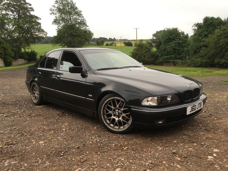

Nearly ready to start, got steel, got donor. First job is to strip it down and remove drive-train

quote:
Originally posted by craigdiver
Nearly ready to start, got steel, got donor. First job is to strip it down and remove drive-train

Looks tidy for a donor!
quote:
Originally posted by Benzo What engine are you pulling from the BM?
quote:
Originally posted by sdh2903
Looks tidy for a donor!
Can anyone else hear that whirring noise?
I think it's Colin Chapman spinning in his grave 
I'd hoped it was a V8 one!
quote:
Originally posted by JAG
Can anyone else hear that whirring noise?
I think it's Colin Chapman spinning in his grave
quote:
Originally posted by Benzo
I'd hoped it was a V8 one!
How many / what bits do I need to use from the BMW to retain the registration?
Planning on engine, gearbox, prop, diff, rear axle including suspension, possibly front suspension, steering column & rack, handbrake, wiring
loom.
Just to be aware the BMW wheels in general are like boat anchors they weigh a bloody ton. My last kit used a BMW donor and it was very tricky to get any reasonable sized lightish wheels with the 5 x 120 stud pattern. Very few avail in 15 inch I ended up with 16s. But then again with a bigger chassis it's probably not such a big issue in your case.
You don't retain the registration. You will just get one of the same year when you apply post IVA.
Engine box and axles is generally enough.
[Edited on 25/7/16 by sdh2903]
quote:
Originally posted by sdh2903
Just to be aware the BMW wheels in general are like boat anchors they weigh a bloody ton. My last kit used a BMW donor and it was very tricky to get any reasonable sized lightish wheels with the 5 x 120 stud pattern. Very few avail in 15 inch I ended up with 16s. But then again with a bigger chassis it's probably not such a big issue in your case.
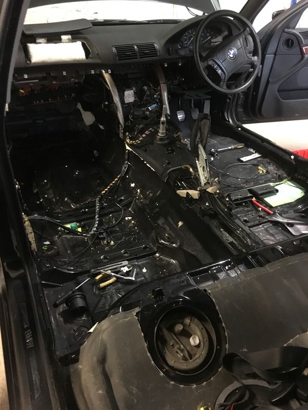
Holy s#!t, started pulling interior panels off the BMW, how much wiring do you actually need in a car!. Little important looking modules hidden everywhere with many wires going to them, think ill wait to see the wiring diagrams in the haynes manual before pulling anything apart
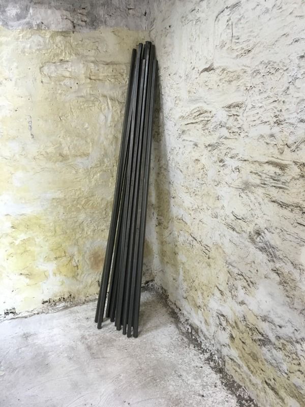
Another step forward, picked up chassis to be from the steel stockholders
It really is shocking. I stripped the Loom out of my V8 one.
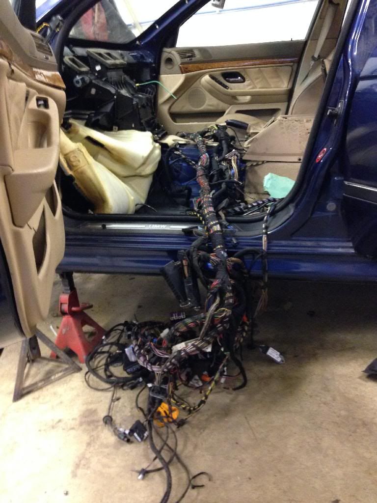
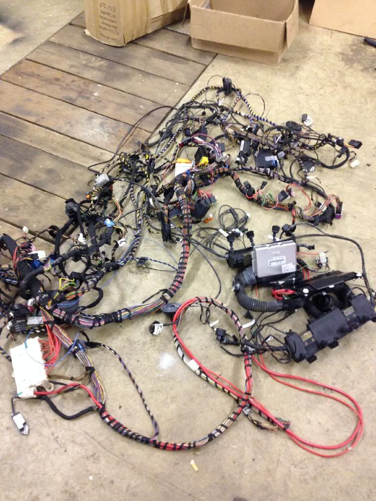
25kg of wiring easily!
quote:
Originally posted by Benzo
It really is shocking. I stripped the Loom out of my V8 one.
quote:
Originally posted by craigdiver
quote:
Originally posted by Benzo
It really is shocking. I stripped the Loom out of my V8 one.
Did you use the engine management part of it or did you use an aftermarket ECU, if so what is the costs/advantages?
MOT history doesn't look bad according to the Gov site.
quote:
Originally posted by tr7v8
MOT history doesn't look bad according to the Gov site.
quote:
Originally posted by Benzo I had intended to run the standard ecu in a chopped down loom
quote:
Originally posted by craigdiver
quote:
Originally posted by Benzo I had intended to run the standard ecu in a chopped down loom
Do you have any info on how much the original loom can be stripped down and what can be removed?
[Edited on 25/7/16 by craigdiver]
6 hours spent today stripping out wiring on BMW. I'm carefully removing it checking as I go that the engine still runs ok.
So far the following circuits are disconnected and engine still running ok;
ABS/ASC sensors
All lighting
Central locking
Climate control
All airbags and airbag module
Fuel tank level sender
Some other modules all over the car that I have no idea what they are.
Sound system
Dashboard warning lights like a xmas tree!
And as a bonus, found 64p in change under seats and other strange places!
The 23i engine pulls good as good as the later m54 25i, although that should have 20 more horses.
On E36 and E46 3-series sometimes these 15x7 alloys are mounted:

They are only 6kg which isn't too bad, I dont know how they fit on 5 series since the offset and centre bore are different.
quote:
Originally posted by ettore bugatti
The 23i engine pulls good as good as the later m54 25i, although that should have 20 more horses.
They are only 6kg which isn't too bad, I dont know how they fit on 5 series since the offset and centre bore are different.
Bet they are.
For EWS removal have a browse here:
http://www.madabout-kitcars.com/forum/showthread.php?t=2512
quote:
Originally posted by ettore bugatti
Bet they are.
For EWS removal have a browse here:
http://www.madabout-kitcars.com/forum/showthread.php?t=2512
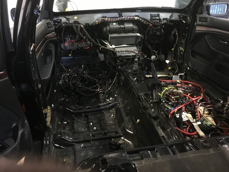
Spent my spare time in the last couple of day's continuing to strip the wiring loom from the BMW.
Now got the dashboard out. Steering column was mounted with a shear-head bolt that is designed not to be removed (for some reason). Fortunately my
special tool (cordless grinder) soon sorted it out. Also have exposed the A/C and heater matrix. The size of the heater matrix is ridiculous and
bigger than the engine cooling radiators on some cars I have owned!
Anyway, here is a photo of the progress.
Absolute obscene the amount of wiring in this BMW.
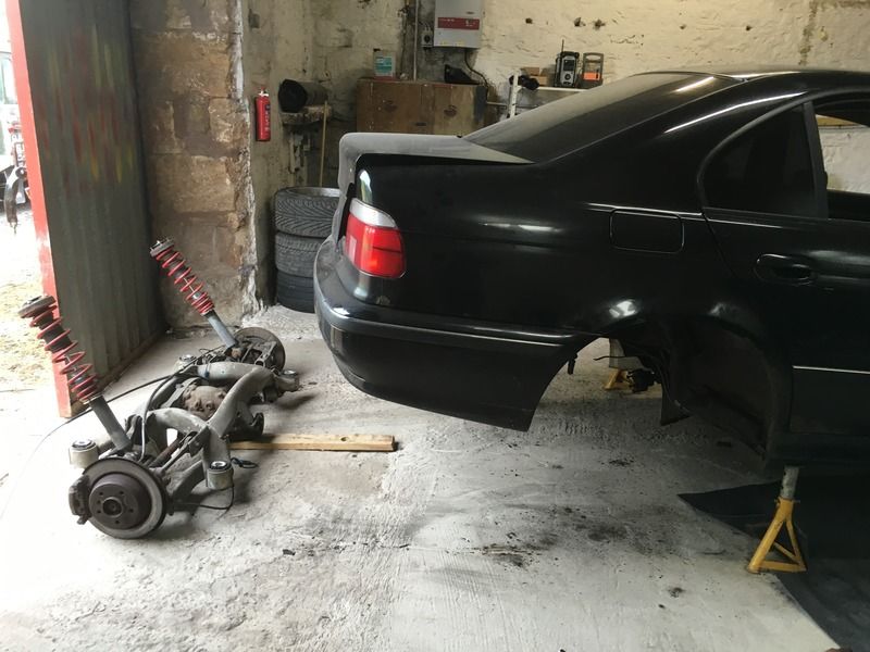
Busy day, rear subframe removed. Really pleased to see lovely adjustable coil-overs.
Subframe weighs a ton, wishbones good so will replicate the wishbone geometry on the back of my chassis and use the huge 18" BMW wheels.
Also started on the front of the car, I noticed the steering rack is in front of the wheels, it may be a steering box rather than a rack (not sure of
the difference). Can I use this or will having power steering be a bit OTT?
I have sierra hubs on order from ebay as want to stick to the tried and tested standard geometry from the book. Going to look at engineering a
solution to allow me to use the 5-stud BMW front wheels, anyone done something similar?
Almost ready to release the beast, just waiting on engine hoist arriving before I go under it to attempt to undo the exhaust downpipes from the
manifold and remove the gearbox mounting.
Disconnected more wiring and almost ready to remove the full wiring loom.
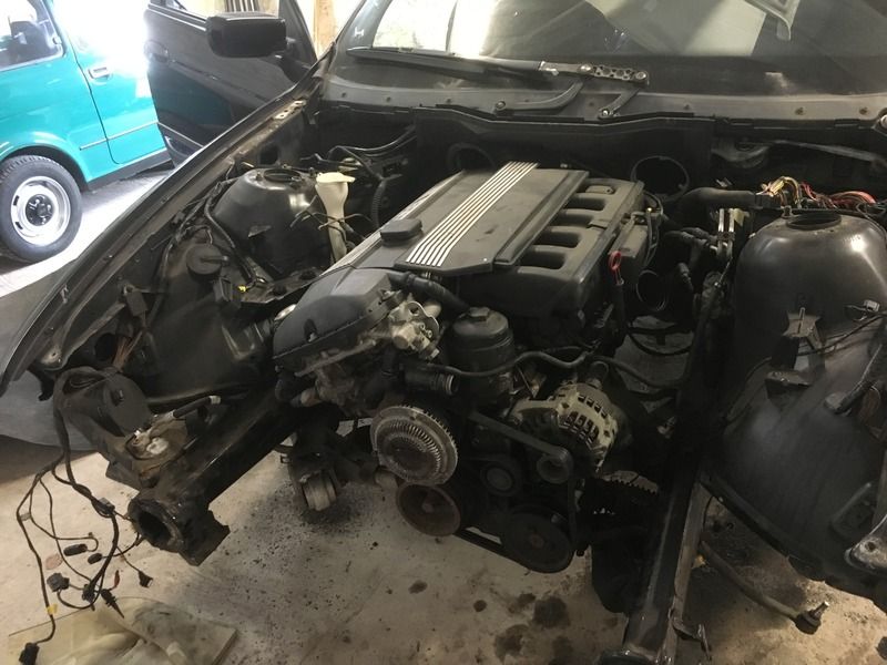
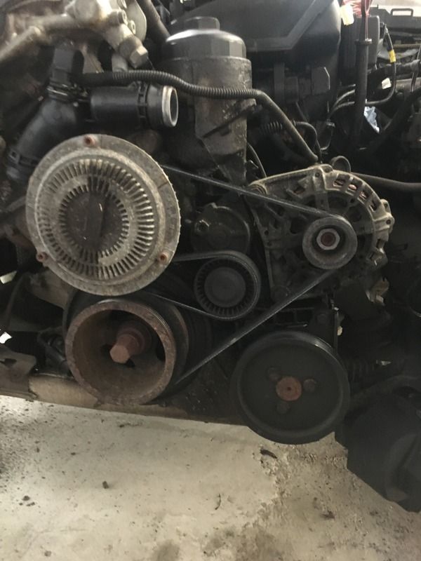
An issue I have come across is how to remove the power steering pump. Managed to remove the aircon pump as that was on its own belt and tensioner but
cannot remove the power steering pump as the pulley is needed in the alternator/water pump loop?
You can see the large power steering pulley below the alternator pulley in the photo above.
Any suggestions?
[Edited on 31/7/16 by craigdiver]
Just use a shorter belt and miss out the pump.
quote:
Originally posted by Schrodinger
Just use a shorter belt and miss out the pump.
quote:
Originally posted by craigdiver
quote:
Originally posted by ettore bugatti
The 23i engine pulls good as good as the later m54 25i, although that should have 20 more horses.
They are only 6kg which isn't too bad, I dont know how they fit on 5 series since the offset and centre bore are different.
Not had the wheels off yet to feel how heavy they are but at 18" I'm sure they won't be light.
Gearbox rear mount removed, Prop shaft removed, fuel tank ready to be dropped. Getting close to removing engine. Once removed, my intention is to run
the engine very briefly (supported by engine hoist) to make sure all ok with the loom and BMW security system issues.
Removed a bit more wiring including the front door looms (just in case). Found another two airbags in the front doors.
Answers on a postcard about how much fun to have with the airbags ;-)
Loom porn (if you are into looms!)
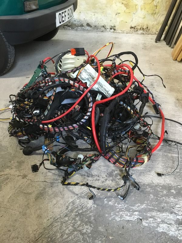
Have been thinking about the BMW rear subframe and have the following idea to engineer its geometry into my 442E;
Going to remove wishbones and fabricate two rigid frames, one left and one right, which pick up the subframe wishbone mounting points. This will allow
me to copy the geometry designed by BMW (think they probably knew what yhey were doing!).
The actual subframe is very heavy and possibly too wide so I intend to make my own subframe based on the two rigid frame mounting points and diff
mounts. Once this lightweight subframe is complete I can incorporate it into the rear of the locost chassis.
Anyone got any suggestions or can see where I'll run into issues?
Hey Craig,
I built an E36 M44 powered Locost and solved some of your issues.
RE to Power steering delete - There are kits around for the E30/E36, it looks the same for the E46 (very cheap). Its just a remove the pipes and banjo
bolt the little plastic (has holes in it to run the oil in a loop) piece on and your done.
RE to belt rubbing issues. Some add a bearing mounted pulley but i instead just made a simple extension bracket for the alternator upper mount and
swung it out to open up some clearance. It clears... just.
There was a locost build going in the US that reused the ear subframe, sadly he didnt finish and i cannnot find the site anymore so it might be
gone.
Basically he got the entire frame to be able to be reused, and installed the mounts off the car into the chassis. I would think this would be heavy
and alot of work.
My option was to make basically Haynes rear uprights, then make a bolt on bearing hub which could take the E36 bearing. You could of course do what
GKD Legend did and make it all 1 piece.
A better solution would be to find a bearing that suits the hubs that is bolt on, i didnt but in hindsight really should have exhausted this option
was making the hub carriers was really one of the weakest links in my build. Took a long time to get them working.
In summary my suggestion:
1. Reuse the driveshafts/diff etc.
2. Ditch the suspension/hubs (lots of weight for little gain, a MX5 bolt in set up at least gives you a complete simple dual a-arms)
3. Workout an OEM bolt on bearing to suit the E46 press in hubs
4. Make some haynes uprights, modified to suit the bolt on bearing you found.
5. Make the longer suspension arms required.
6. Get some wide guards, i found my rear was just too wide to fit the tyres. The haynes chassis width works fine so dont change that.
7. Enjoy the BMW engine and box powering something that lost 1000kg off its normal weight.
5 series had bolt on bearings, i didnt check to see if you could put the 3 series shafts into a 5 series hub or possibly just bolt a set of 5 series
shafts to the diff.
cheers,
Taffy
BMW EWS
Remember to keep the key, transcoder and ECU.
I kept the system in my build. After it got working there were no problems... before that... Its a nightmare as you have no idea if its key, trans
coder or ECU issue or wiring in between. I had to replace the ring around the ignition barrel as i found i had a break in the wiring that if it was
moved would mean you could not start the car.
Its actually a fairly straight forward system if you just joining the BMW parts and treating them as black boxes. The newer ODB2 cars to get a delete
done is a send away job, and unless you are doing a power upgrade i would not bother.
Just draw out the wiring diagram and be clear on each connection, map the power/grounds etc so you can test those at each step.
Cheers,
Taffy
Wow - thank you Taffy for the great info. Going to have a think about what you have said and may have a few questions (if that is ok?)
Did you do a build diary with photos?
Cheers
Craig
quote:
Originally posted by ftaffy
RE to belt rubbing issues. Some add a bearing mounted pulley but i instead just made a simple extension bracket for the alternator upper mount and swung it out to open up some clearance. It clears... just.
quote:
Originally posted by ftaffy
In summary my suggestion:
1. Reuse the driveshafts/diff etc.
2. Ditch the suspension/hubs (lots of weight for little gain, a MX5 bolt in set up at least gives you a complete simple dual a-arms)
3. Workout an OEM bolt on bearing to suit the E46 press in hubs
4. Make some haynes uprights, modified to suit the bolt on bearing you found.
5. Make the longer suspension arms required.
6. Get some wide guards, i found my rear was just too wide to fit the tyres. The haynes chassis width works fine so dont change that.
7. Enjoy the BMW engine and box powering something that lost 1000kg off its normal weight.
5 series had bolt on bearings, i didnt check to see if you could put the 3 series shafts into a 5 series hub or possibly just bolt a set of 5 series shafts to the diff.
cheers,
Taffy
how do granada 5 stud wheels compared with the bm? iirc the early granada was very similar to the sierra so you might get away with using the granada hubs or if nothave the redrilled to bm pcd.
quote:
Originally posted by ftaffy
BMW EWS
Remember to keep the key, transcoder and ECU.
I kept the system in my build. After it got working there were no problems... before that... Its a nightmare as you have no idea if its key, trans coder or ECU issue or wiring in between. I had to replace the ring around the ignition barrel as i found i had a break in the wiring that if it was moved would mean you could not start the car.
Its actually a fairly straight forward system if you just joining the BMW parts and treating them as black boxes. The newer ODB2 cars to get a delete done is a send away job, and unless you are doing a power upgrade i would not bother.
Just draw out the wiring diagram and be clear on each connection, map the power/grounds etc so you can test those at each step.
Cheers,
Taffy
quote:
Originally posted by Schrodinger
how do granada 5 stud wheels compared with the bm? iirc the early granada was very similar to the sierra so you might get away with using the granada hubs or if nothave the redrilled to bm pcd.
Couldn't you use what GKD are using?
quote:
Originally posted by ettore bugatti
Couldn't you use what GKD are using?
Hey,
What GKD did was not road legal in Australia (well my engineer would not sign it off). So i went with mushrooms inside the cut down mcpherson
struts.
My build can be seen in the pdfs here, missing the last few which i will need to pull off the other computer and put up when i get a chance.
https://drive.google.com/open?id=0B64orUhbOtS_X3NxRDI4WS1nYkU
FYI i am in Australia so some of things i had to do probably wont apply in your case.
quote:
Originally posted by ftaffy
Hey,
What GKD did was not road legal in Australia (well my engineer would not sign it off). So i went with mushrooms inside the cut down mcpherson struts.
My build can be seen in the pdfs here, missing the last few which i will need to pull off the other computer and put up when i get a chance.
https://drive.google.com/open?id=0B64orUhbOtS_X3NxRDI4WS1nYkU
FYI i am in Australia so some of things i had to do probably wont apply in your case.
How odd, its set to sharing for anyone who can see the link.
Anyone else cannot see it?
Thanks,
Taffy
quote:
Originally posted by ftaffy
How odd, its set to sharing for anyone who can see the link.
Anyone else cannot see it?
Thanks,
Taffy
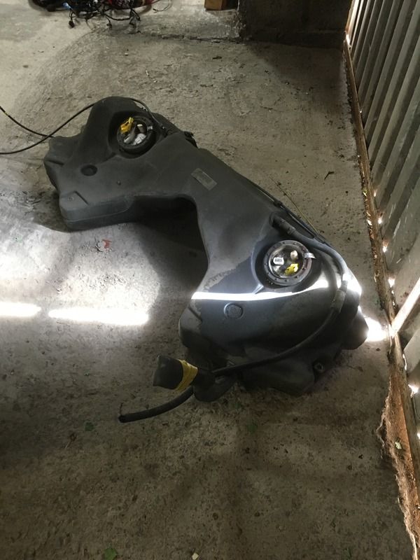
Donor now relieved of fuel tank - not going to be used in final build but handy for testing engine as I build until new fuel tank fabricated.
Was a complete pig to remove, all the fixings badly corroded and its not exactly the best place to get in about it with the grinder 


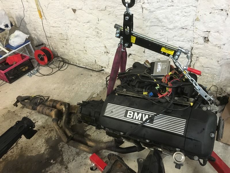
Freeing the beast!, now got the engine out. Now need to get rid of a ton of BMW bodyshell so I have more room to work - been quoted a cost of £50 for
a scrappie to pick it up with a hiab, does this sound reasonable or should it be getting picked up for free for the value of the scrap metal?
[Edited on 7/8/16 by craigdiver]
I dont know about the UK but in Aus the price of scrap is slow low no will touch car bodies unless you drop them off or they are on wheels. Dont want
to scratch the paint on the trays.
Glad to hear the link worked.
Nice engine
My engine weighs 175kg, getrag gearbox 30kg.
How does that compare to the original ford pinto engines, was the pinto much lighter?
Finally got whats left of the BMW out of my workshop - went for the brute force method and dragged it out with my pickup!

Going to fire up engine (very briefly - no coolant) to make sure loom and BMW EWS security system still ok before I start stripping out the stuff I
don't need from the loom (most of it!).
If you look closely you will see my orange OBDII scanner attached, prize to anyone who guesses the quantity of fault codes it throws up 
 image post
Your better off having the DME reprogrammed to remove the EWS so you can get rid of the wiring mess that is causes.
Its easy to do as a DIY or there a few people on eBay that will do it for you.
Edit. You will need the help of this site, full wiring diagrams for the car http://www.bmw-planet.net/diagrams/release/en/
[Edited on 8/8/16 by james-w]
quote:
Originally posted by james-w
Your better off having the DME reprogrammed to remove the EWS so you can get rid of the wiring mess that is causes.
Its easy to do as a DIY or there a few people on eBay that will do it for you.
Edit. You will need the help of this site, full wiring diagrams for the car http://www.bmw-planet.net/diagrams/release/en/
[Edited on 8/8/16 by james-w]

What version of DME is it, my engine from the 528i is M52 all aluminium lump which came with MS41.0?
If it is that then here is the best place to learn how to do it, if you need any pointers let me know.
http://www.romraider.com/forum/viewforum.php?f=42
quote:
Originally posted by craigdiver
Also started on the front of the car, I noticed the steering rack is in front of the wheels, it may be a steering box rather than a rack (not sure of the difference). Can I use this or will having power steering be a bit OTT?
I have sierra hubs on order from ebay as want to stick to the tried and tested standard geometry from the book. Going to look at engineering a solution to allow me to use the 5-stud BMW front wheels, anyone done something similar?
quote:
Originally posted by craigdiver
quote:
Originally posted by Benzo I had intended to run the standard ecu in a chopped down loom
Do you have any info on how much the original loom can be stripped down and what can be removed?
[Edited on 25/7/16 by craigdiver]
quote:
Originally posted by james-w
What version of DME is it, my engine from the 528i is M52 all aluminium lump which came with MS41.0?
If it is that then here is the best place to learn how to do it, if you need any pointers let me know.
http://www.romraider.com/forum/viewforum.php?f=42
That's a hell of a project.
Will keep an eye on this buddy 
quote:
Originally posted by TheHighlander123
That's a hell of a project.
Will keep an eye on this buddy

Got the welder set up and done a trial weld on a couple of bits of the 1" 16 guage tube, happy with weld. Welding like riding a bike, been a
while but still got it - no blow through and good penetration. Should keep Mr SVA happy 
 screen shots
[Edited on 11/8/16 by craigdiver]
A1, A2, B1 & B2 cut and on worksurface. But working away till middle of next week so will have to wait to lay the first weld (or tack!).

Looking at designing in something similiar to the haynes roadster back end so I can use wishboned from the BMW rear subframe.
I have the haynes roadster chassis on solidworks but cannot see the wall thickness on the larger box section used in the rear subframe.
Anyone got the haynes roadster book, and can take a look?
Cheers
Craig
Got a bit distracted and decided to have some fun with the BMW airbags......
https://youtu.be/HJrsG2hlNuo
I expected the plastic chair to be launched into the air
[Edited on 13/8/16 by craigdiver]
Needing some advice......
Keep looking at BMW rear subframe (photo of it on page 2) and am thinking that with 4 strategically placed mounts the complete subframe would just
bolt on, this would mean;
(1) little suspension setup whatsoever - instant wishbone suspension, would need to make simple bracket to mount coil-overs.
(2) looks good width wise for 442E chassis - may need slightly wider rear arches (are they readily available or will I have to make myself?)
(3) no faffing around trying to modify other hubs to take BMW alloys
(4) instant drivetrain, just need to shorten prop and change diff gear oil.
Bad points
(1) weight, it is a heavy beast but the engine has torque and maybe a good idea to have a bit of weight in the back for grip?
Any thoughts anyone.....?
[Edited on 17/8/16 by craigdiver]
quote:
Originally posted by craigdiver
Needing some advice......
Keep looking at BMW rear subframe (photo of it on page 2) and am thinking that with 4 strategically placed mounts the complete subframe would just bolt on, this would mean;
(1) little suspension setup whatsoever - instant wishbone suspension, would need to make simple bracket to mount coil-overs.
(2) looks good width wise for 442E chassis - may need slightly wider rear arches (are they readily available or will I have to make myself?)
(3) no faffing around trying to modify other hubs to take BMW alloys
(4) instant drivetrain, just need to shorten prop and change diff gear oil.
Bad points
(1) weight, it is a heavy beast but the engine has torque and maybe a good idea to have a bit of weight in the back for grip?
Any thoughts anyone.....?
[Edited on 17/8/16 by craigdiver]
quote:
Originally posted by james-w
The existing coilovers will be no good to you as they are sprung and valved for a car that weighs 1500kg and can carry 3 passengers in the back and a boot full of shopping.
If you do want to go down the IRS route some have used the Rorty designs on a 442.
http://locost7.info/files/suspension/RortyLocostIRSAssembly.pdf
Mine was designed with the help of this site http://www.racingaspirations.com/apps/suspension-geometry-calculator
quote:
Originally posted by james-w
If you do want to go down the IRS route some have used the Rorty designs on a 442.
http://locost7.info/files/suspension/RortyLocostIRSAssembly.pdf
Mine was designed with the help of this site http://www.racingaspirations.com/apps/suspension-geometry-calculator
If you have a close look at the diff you will see the input is off centre so is a right pain to fit.
Also epends if you will want an LSD or not as the only e39 that had one is the M5. You could look at other options like Mazda RX8 which I believe has
an LSD in all models bar the automatic.
Re-using the subframe could be an attractive alternative if you were building a ladder framed cruiser, but then you want to re-use the front
suspension assembly as well.
You might just end up building a 6-series...
Hey Mate,
I came across a list of cars which use the same size wheel bearing as an E36 on the rear (the hub can be pressed in and the shafts reused)
I have not confirmed any of this, so do your homework before using!
ALFA 33 2WD 1984-3/1989
ALFA 33 4WD 1985-1987
AUDI 100 1.9L 1974-1987
AUDI 100 1.9L 1983-9/1985
AUDI 200 1982-1984
BMW REAR 316i E36 1995-1999 (WITH TRACTION CONTROL)
BMW REAR 316ti E46 1999-2005
BMW REAR 318i E46 1998-2005
BMW REAR 318is E30 1990-1991
BMW REAR 318is E36 1992-1999
BMW REAR 318ti E46 1998-2005
BMW REAR 320i E36 1991-1995
BMW REAR 320i E46 2000-2004
BMW REAR 320ci E46 2000-2006
BMW REAR 323i E36 1996-1998
BMW REAR 323i E46 1998-2000
BMW REAR 323ci E46 1999-2002
BMW REAR 325e E30 1986-1987
BMW REAR 325i E30 1988-1990
BMW REAR 325i E36 1991-1995
BMW REAR 325i E46 2000-2004
BMW REAR 325i E90, E92, E93 2005
BMW REAR 325ci E46 2000-2006
BMW REAR 325ti E46 2002-2005
BMW REAR 328i E36, E46 1993-2000
BMW REAR 328ci E46 1999-2002
BMW REAR M 1998-2003
BMW REAR Z4 A85 2003
BMW REAR Z3 6CYL EXCEPT 3.2L 1997
MERCEDES FRONT A CLASS 168 1997-2004
PORSCHE REAR 911 IRS 1968-1973
PORSCHE FRONT 911 993 2WD & AWD 1994-1998
PORSCHE FRONT 911 996 1996-2006 (EXCEPT GT-2,GT-3)
PORSCHE FRONT BOXTER 986 2.5L, 2.7L 1997-2004
PORSCHE REAR BOXTER 986 2.5L, 2.7L 1997-2004
PORSCHE FRONT BOXTER 986 3.2L 1999-2001
PORSCHE FRONT BOXTER 986 3.2L 2002-2004
quote:
Originally posted by ftaffy
Hey Mate,
I came across a list of cars which use the same size wheel bearing as an E36 on the rear (the hub can be pressed in and the shafts reused)
I have not confirmed any of this, so do your homework before using!

Sorry forgot your not using the E36.
The E39 is a bolt on bearing pack isnt it? Thats pefect for locost application, just use the Haynes upright and modify to suit the bolt spacing on the
bearing.
And check the wheel offset/scrub obviously.
From my understanding the E39 series bearing is stand alone, so you wont find an off the shelf upright that will suit your needs.
Cheers,
Taffy
Yes the E39 bearing is a standalone bolt on so it may be possible to modify the standard Haynes upright, i made custom ones for my car so I could use
the wheel bearings.
If you do use the E39 wheel bearing you will need to machine the hub slightly to accept other BMW wheels or you will be limited to only using the E39
wheels due to the bore size. E39 are 74.1mm and all other wheels are 72.56m
quote:
Originally posted by james-w
Yes the E39 bearing is a standalone bolt on so it may be possible to modify the standard Haynes upright, i made custom ones for my car so I could use the wheel bearings.
If you do use the E39 wheel bearing you will need to machine the hub slightly to accept other BMW wheels or you will be limited to only using the E39 wheels due to the bore size. E39 are 74.1mm and all other wheels are 72.56m
Holy crap - LA & LB had my brain hurting but fluked them in the end.....
Just love compound angle cuts
 upload pictures
Chassis gone 3D, feeling chuffed :-)
 upload a
picture
Added a few upper rails, fitting together nicely.
Any advice on engine placement, can I have an inch of sump sticking out the bottom?
 photo upload
sites
quote:
Originally posted by craigdiver
Any advice on engine placement, can I have an inch of sump sticking out the bottom?

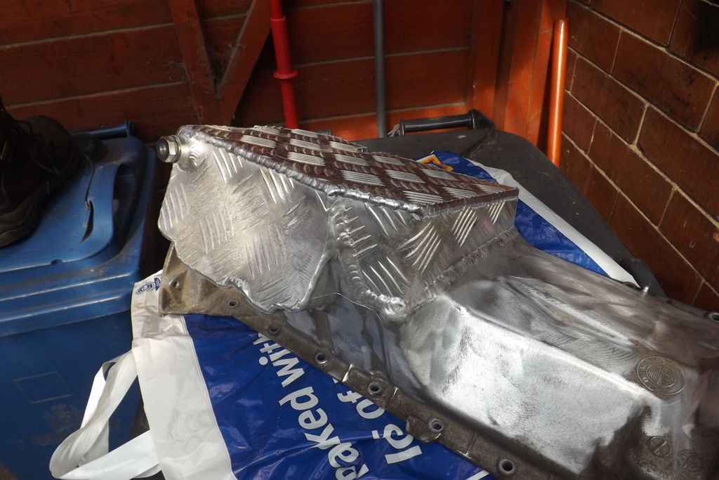
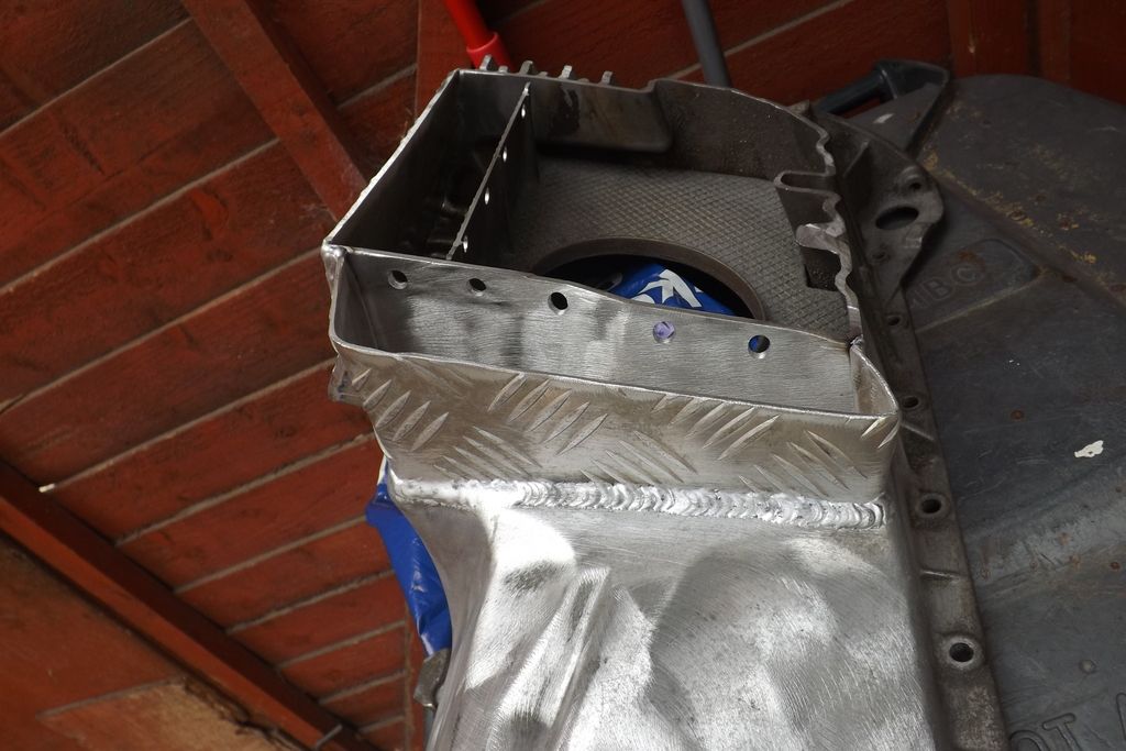
Great work Nickp, think ill opt for an inch below frame with sump guard and bulge in bonnet or a cutout displaying BMW engine covers (if it is SVA compliant?)
Wow Nick that is fairly intensive piece of work.
Am i right to assume the M52 also has a Alloy sump? The M44 i used had once as well but i outsourced its mods to a pipe welder.
Craig - i cut 25mm off the sump + added a mustang scoop and it still hangs out the bottom of a 115mm ride height Haynes height chassis car and i have
hit it hard a few times. Going to need an engine out repair soon as it leaks on cool down.
A sump guard is a good move and the direction i am going and possibly adding an accusump once i get the high speed issues (light front end, drive line
vibration and an aero screen) sorted and tackle some track days.
Cheers,
Taffy
quote:
Originally posted by craigdiver
Holy crap - LA & LB had my brain hurting but fluked them in the end.....
Just love compound angle cuts
upload pictures
quote:
Originally posted by ftaffy
Wow Nick that is fairly intensive piece of work.
Am i right to assume the M52 also has a Alloy sump? The M44 i used had once as well but i outsourced its mods to a pipe welder.
Craig - i cut 25mm off the sump + added a mustang scoop and it still hangs out the bottom of a 115mm ride height Haynes height chassis car and i have hit it hard a few times. Going to need an engine out repair soon as it leaks on cool down.
A sump guard is a good move and the direction i am going and possibly adding an accusump once i get the high speed issues (light front end, drive line vibration and an aero screen) sorted and tackle some track days.
Cheers,
Taffy
quote:
Originally posted by james-w
quote:
Originally posted by craigdiver
Holy crap - LA & LB had my brain hurting but fluked them in the end.....
Just love compound angle cuts
upload pictures
You will need to modify the front if you want to use a standard Haynes nosecone as its too wide at the top.
Equinox have the dimensions of all their parts on their Facebook page.
Now got complete set of Sierra running gear, what calipers / brake discs do I fit to the front hubs, sierra ones or something else?
 picture share
Been mega busy with work so only managed bits and pieces over the last few weeks;
Got the sierra hubs sand blasted and etch primed, thinking black, anybody tried other colours? Silver? Do I need bare metal in the tapers or is a thin
coat of primer ok?

Removed BMW diff from subframe (its heavy), found the subframe to be aluminium so cannot reuse mounts, any ideas anyone?

Picked up some, very cheap - £50, ford focus zetec alloys, ET offset probably not suitable for car but will give me a rolling chassis until I win the
lottery and buy some magnesium billet wheels!

Also got a load of welding done on the chassis, going to do front suspension setup then have a first trial fit if engine to determine placement of
engine bay rails etc.
quote:
Originally posted by james-w
You will need to modify the front if you want to use a standard Haynes nosecone as its too wide at the top.
Equinox have the dimensions of all their parts on their Facebook page.
I´d leave the primer on the tapers until ready to assemble,
then a light sanding to remove.
Well not quite, building of real car on hold due to no heating in my workshop, however, my Lego Caterham 7 model has now been built and passed my own
rigorous inspection!
 image hosting
10mb limit
[Edited on 25/12/16 by craigdiver]
Excellent and nice jumper lol
Good progress over the last week, finished building 'phase 1' of my chassis and had my friend Jim (coded welder) fully weld it up. He took
great pleasure ripping the poo out of my welding skills (I thought I had done ok!). Next job is to test fit engine to get engine mount placement,
measurements for transmission tunnel etc., then can start building rear end.
Jim in action, makes welding look easy
 photoupload
Looking good....
 upload image free
Decided to drop the engine into the engine bay to see what modifications are needed to the chassis rails to fit it in - good news is that it will fit, but holy crap, its tight! Ill post photos once I get it into its final position and onto its mounts. I'm glad I went for the modified chassis with a longer and talker engine bay.
quote:
Originally posted by craigdiver
Decided to drop the engine into the engine bay to see what modifications are needed to the chassis rails to fit it in - good news is that it will fit, but holy crap, its tight! Ill post photos once I get it into its final position and onto its mounts. I'm glad I went for the modified chassis with a longer and talker engine bay.
 The gearbox bellhousing is probably the biggest problem. With the engine
right back and central it wants to hit the driver footwell upright, but if you move it over the sump hits the lower passenger side engine bay rail
even more than it already was. I shaved the lugs off the gearbox on the drivers side and managed to keep it central(ish).
 Here's a few engine positioning shots for reference-
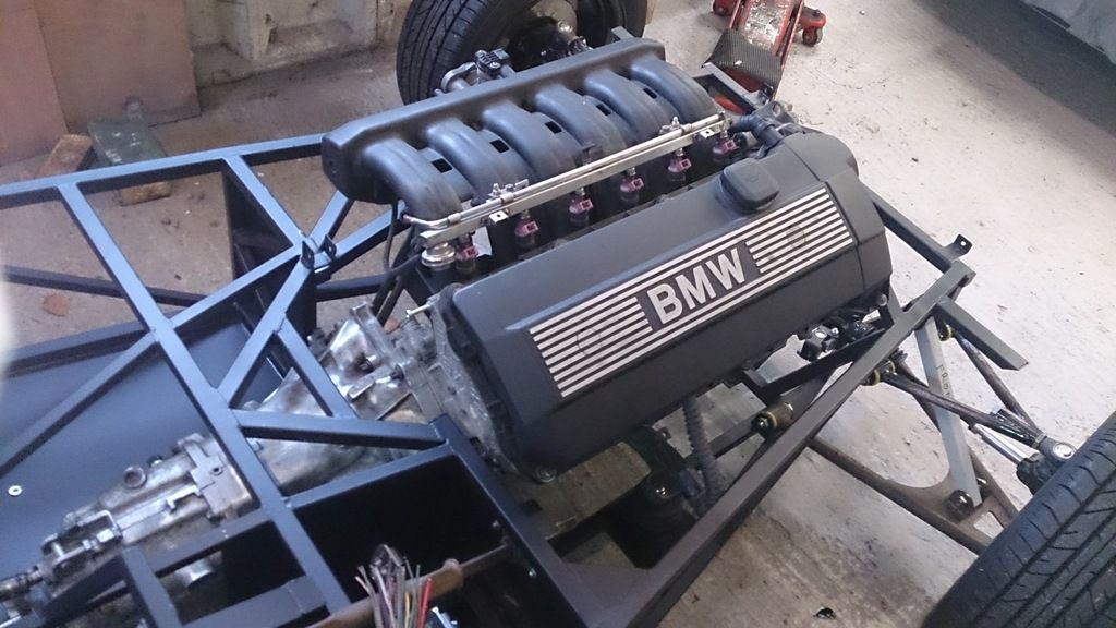
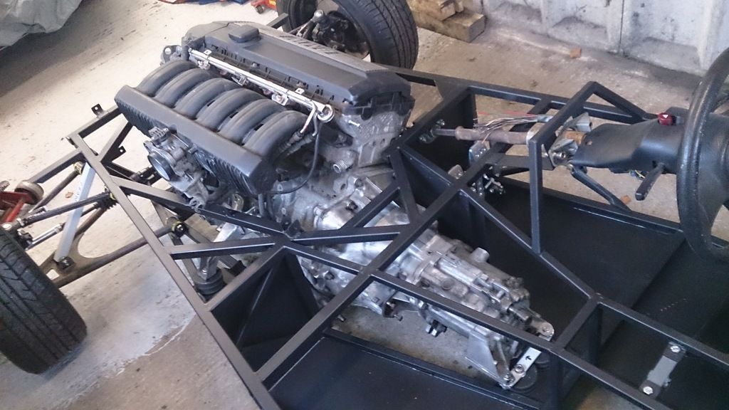
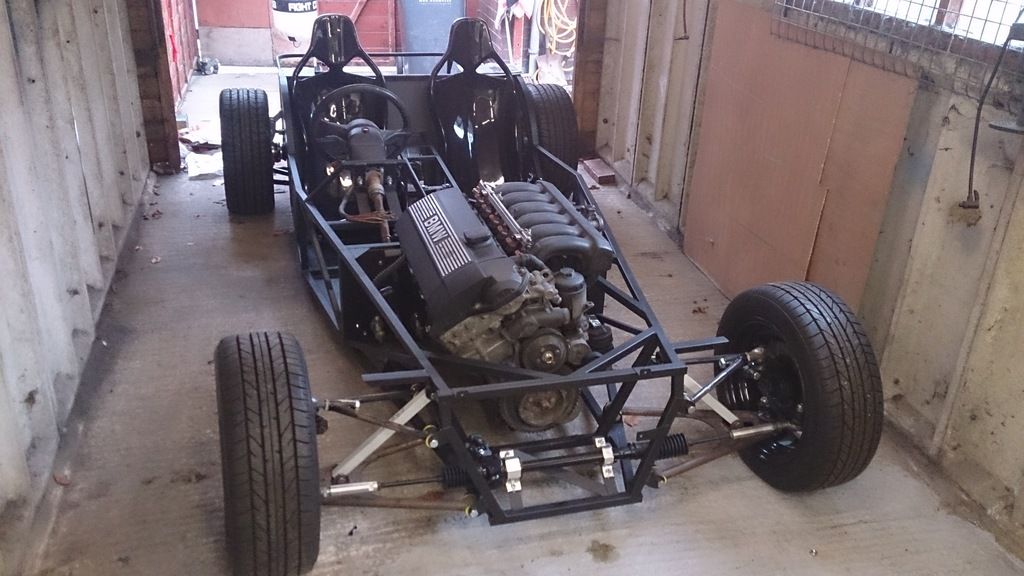
Nickp, wow, photos are so helpful, thank you.
Craig :-)
NickP, have you worked out how to connect the coolant system yet as I noticed two cooling circuits, one for the cylinders and one for the head, plus a water pump and thermostat?
quote:
Originally posted by craigdiver
NickP, have you worked out how to connect the coolant system yet as I noticed two cooling circuits, one for the cylinders and one for the head, plus a water pump and thermostat?
quote:
Originally posted by Nickp
quote:
Originally posted by craigdiver
NickP, have you worked out how to connect the coolant system yet as I noticed two cooling circuits, one for the cylinders and one for the head, plus a water pump and thermostat?
Yeah I think so, what you need to know?
I went for the bigger 1.6 Polo rad, don't know if it's big enough yet, only time will tell.
Basics of cooling system-
Outlets at front of engine- n/s goes to top of rad, o/s goes to bottom of rad, as per BMW.
Metal pipe that runs along n/s of engine- rear outlet connects to port at rear of head (basically bypassing the heater), port 1/2 way along pointing
to n/s goes to bottom of expansion tank.
I've put a small outlet in the top hose that connects to the top of the expansion tank (VW globe type).
Water temp sensor tapped off TB water pipes.
This is just how I've done and it seems OK so far but is yet to be tested properly.
quote:
Originally posted by Nickp
I went for the bigger 1.6 Polo rad, don't know if it's big enough yet, only time will tell.
Basics of cooling system-
Outlets at front of engine- n/s goes to top of rad, o/s goes to bottom of rad, as per BMW.
Metal pipe that runs along n/s of engine- rear outlet connects to port at rear of head (basically bypassing the heater), port 1/2 way along pointing to n/s goes to bottom of expansion tank.
I've put a small outlet in the top hose that connects to the top of the expansion tank (VW globe type).
Water temp sensor tapped off TB water pipes.
This is just how I've done and it seems OK so far but is yet to be tested properly.
Bit more done of the chassis, should get rear end done this week but will be build as you go to suit the BMW diff. Still having issues sourcing
seamless tube for wishbones (without being ridiculous price!).
 20mb image hosting
[Edited on 22/4/17 by craigdiver]
Was in a Citroen van the other day and the handbrake was to the right of the drivers seat, anyone put their handbreak just in front of the drivers seat on the right hand side rather than on the transmission tunnel? I've had my seat in place and guesstimate the released handbrake would be clear of my leg and out the way.
Back end getting sorted now, these are a bit time consuming but getting there (just waiting for them to cool from welding then cracking on!)
 greenshot[/u
rl][url=https://certificity.com]certificity.com
12 hour shift in the workshop and now knackered but great progress, managed to get the following done today;
- Welded in front upper shock mounts.
- fabricated brackets and mounted steering rack (and checked the track rod ends are right).
- fabricated custom steering shaft and fitted.
- painted sierra front hubs silver, they look like new!
- modified prop shaft, had collars turned to shorten each section. Fabricated mount for UJ.
- got diff into place (bloody BMW diff weighs a tonne, had to use engine hoist!). Fabricated mounting brackets.
- BMW handbrake mounted on fabricated brackets.
Only got a bit of welding to do on newly fitted brackets, rear suspension brackets to be welded on and fuel tank support brackets then I can paint the
chassis.
NickP, after fitting the steering shaft it looks like I might have to copy you and go one up and one down on the exhaust manifolds.


[Edited on 17/6/17 by craigdiver]
Out of interest, is anyone actually following my build? If so, let me know what detail I need to add to make the information more useful to you.
Cheers
Craig
Yes, I am!
I'm watching also and enjoying it as it is coming. Only thing are the brackets for the rack not a little thin?
looking good! Yes...watching... all good so far..
Yep, still watching in a dejavu kinda way 
quote:
Originally posted by hearbear
I'm watching also and enjoying it as it is coming. Only thing are the brackets for the rack not a little thin?
quote:
Originally posted by Nickp
Yep, still watching in a dejavu kinda way
Some pics of the sleeves made to shorten the propshaft. The BMW propshaft is friction welded so needs to be shortened by cutting/joining/welding then
balancing;


Will get it TIG welded by a professional then balanced.
Butchered the steering shaft components along with a length of thick walled tube to make the steering shaft. Needs TIG welded. Concerned heat may
damage rubber on end. May need to weld a bit at a time dipping it in cold water to protect it, any suggestions anyone?
Note the roll pins to keep Mr SVA happy (as if they will hold if the welds fail for whatever reason!)


[Edited on 6/7/17 by craigdiver]
Any reason why you've left the rubber in there? I did away with it with a UJ top and bottom to remove any rubberyness 
quote:
Originally posted by Nickp
Any reason why you've left the rubber in there? I did away with it with a UJ top and bottom to remove any rubberyness
i have a z cars jig for top and bottom wishbones and mabye still got some tube for making them if your interested .
[Edited on 7/7/17 by bigwill64]
quote:
Originally posted by craigdiver
quote:
Originally posted by hearbear
I'm watching also and enjoying it as it is coming. Only thing are the brackets for the rack not a little thin?
3mm as per book, I'm sure it read 3mm, or does it look thinner in the photo :-0
looking good.
i'm not here every day but i'm following it now and then and here and there.
keep up the nice work!
quote:
Originally posted by bigwill64
i have a z cars jig for top and bottom wishbones and mabye still got some tube for making them if your interested .
[Edited on 7/7/17 by bigwill64]
Another very productive day, fitted fuel tank mounting brackets, rear suspension brackets, diff cage braces, headlight brackets and got everything
else fully welded.
Had an idea for the headlight brackets. I welded a small bore hollow tube through the chassis rail and mounted the headlight bracket over it so the
headlight wires can enter the end of the headlight bracket and straight through to the inside of the chassis.


Still got the infill pieces to weld in for the rear arches but want to wait till I have the arches (which I will get when I have assembled the rear
suspension and know how wide to go).
Also still need to weld on a couple of brackets to take the ends of the roll hoop supports.
Chassis now undercoated with red anti-corrosion primer. Feeling high as a kite after thoroughly cleaning chassis with solvent based degreaser then
painting with the solvent based paint!. Now have brush strokes & the odd bristle on my chassis to add a bit of character! :-)

[Edited on 10/7/17 by craigdiver]
[Edited on 10/7/17 by craigdiver]
Got the BMW diff shot blasted, was looking very sorry for itself with thick layers of rust but what a transformation after shot blasting &
painting....


Car is going to be BMW Yas Marina Blue, tempted to paint the diff cover with the same colour, not sure why people paint the diff cover a different
colour but would look good.
Diff will be first to be mounted (after an oil change) once floor fitted this weekend.

[Edited on 14/7/17 by craigdiver]
Nice car that was lol
quote:
Originally posted by jossey
Nice car that was lol
Measured out 4mm rivet holes (max 40mm spacing) and drilled the 127 holes. I had ordered 4.1mm drill bits but never turned up so drilled in 4.0mm,
rivets tight to get into hole so may wait till 4.1mm bits turn up to silkaflex and rivet floor 2mm aluminium on.
Anyway, here is progress so far (the 4 larger holes are so I can access the bolts for the seat subframe, I have plugs for the holes)

When I'm upside down in a field I'm sure the first thing that the accident investigator will think is nice floor-pan ;-)

Made jig up for rear hubs, thought would be a good idea to pad out long M12 threaded by wrapping PVC tape round it to centralise the tube - worked
perfectly. However, after I welded it I realised the cock-up, how am I going to get it out! Think will apply heat with a gas mask on until the tape
melts sufficiently to pull the threaded bar out!
Just noticed the book Figs 5.23, 5.28 & photo 5.32 are clearly dimensionally different to the drawing 5.24.
I am going with sierra drum brakes, am I ok to rotate the hub mounting plate a bit to give better access to the brake shoe cylinder connection? (Seen
this discussed elsewhere)

[Edited on 18/7/17 by craigdiver]
Diff mounted in chassis with help from my son Matthew, going to remove and refit 2 x rear mounting bolts and insert from the front so they can be
removed in the future without having to remove the fuel tank.


Wrote a letter this evening to K and R, DVLA requesting a VIN number. Letter will be posted Monday, let's see how long it takes.
Just scared myself by making a quick to-do list, I'm sure there is probably loads of other bits and pieces but here goes;
Car todo
- Fit brackets to catch roll bar braces on rear upper tube.
- Fit rear arch infill brackets
- Buy roll hoop, cross member, support bars & seatbelt mounts £100
- Buy ECU £145
- Buy steering rack extensions
- Buy rear wheel arches
- Buy front wheel arches
- Measure up and buy sleeves to join BMW & sierra drive shafts
- Buy new shoes and fitting kits for rear hub brakes
- Buy custom handbrake cables
- Buy universal throttle cable
- Buy flexi clutch hydraulic hose
- Buy headlights
- Buy front indicators
- Buy rear lights & repeaters
- Buy battery
- Buy set of shocks
- Buy seatbelts
- Get seatbelt mounting bolts from scrappies
- Get wheelnuts for ford focus from scrappies
- Buy brake & clutch fluid reservoir including pipes to master cylinder & level sensor
- Cut nosecone and get grille
- Buy & fit oil cooler
- Buy water cooling pipework
- Buy oil cooler pipework
quote:
Originally posted by craigdiver
Diff mounted in chassis with help from my son Matthew, going to remove and refit 2 x rear mounting bolts and insert from the front so they can be removed in the future without having to remove the fuel tank.


quote:
Originally posted by rodgling
I suspect that will not be strong enough - on my car which originally had this diff mounted in the same way with just three mount points, the front bolt snapped as the nose of the diff tries to lift up under acceleration (IIRC this happened while I still had the 328 engine).
There should be a couple of mount points directly under the output shafts - I would recommend running a chassis rail underneath these and mounting vertically through these. I've done this and this appears to have solved the problem.
My diff (medium case, which I think the 325 diff is) looks like the one here:
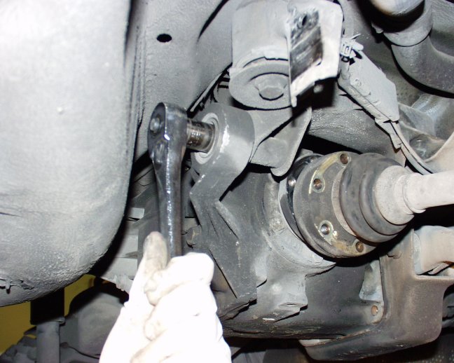
The mounts I used are to the right of the hand, underneath the driveshaft.
I'd definitely suggest beefing up the front mount as much as you can, I would drill out the hole and use as big a bolt as possible, also maybe
brace the tab on the chassis a bit.
quote:
Originally posted by rodgling
My diff (medium case, which I think the 325 diff is) looks like the one here:
The mounts I used are to the right of the hand, underneath the driveshaft.
I'd definitely suggest beefing up the front mount as much as you can, I would drill out the hole and use as big a bolt as possible, also maybe brace the tab on the chassis a bit.
Ah, that explains the diff diff then. The front mount on mine is M12, so I guess the M14 bolt will help.
quote:
Originally posted by rodgling
Ah, that explains the diff diff then. The front mount on mine is M12, so I guess the M14 bolt will help.
quote:
Originally posted by craigdiver
quote:
Originally posted by rodgling
Ah, that explains the diff diff then. The front mount on mine is M12, so I guess the M14 bolt will help.
I see from your profile you have went with M3 power, was it reasonably straightforward to swap from 2.8 to M3 lump? I was hoping to do the power upgrade in mine once finished, SVA'd, MOT'd and driven it around for a few months.
quote:
Originally posted by rodgling
quote:
Originally posted by craigdiver
quote:
Originally posted by rodgling
Ah, that explains the diff diff then. The front mount on mine is M12, so I guess the M14 bolt will help.
I see from your profile you have went with M3 power, was it reasonably straightforward to swap from 2.8 to M3 lump? I was hoping to do the power upgrade in mine once finished, SVA'd, MOT'd and driven it around for a few months.
Yeah, very easy. You may need to tweak the chassis for clearance around the vanos area, also the air box and maf are pretty big so may be a squeeze. But otherwise it's straightforward. Hardest part is probably justifying the cost of the m3 engine, they're not cheap these days :-) Everything is in the same place in terms of mounts, gearbox fitment etc.
The s50b32 is supposed to be 321 bhp when new, so I guess a bit less than that. Some horses lost to age I expect, but some savings made by removing
fan, power steering, EGR, plus freer flowing exhaust, lightweight flywheel. Its fast though, I don't feel the need for any more power :-) It will
outdrag a 997 GT3 RS4, so I'm happy with the performance.
[Edited on 23/7/17 by rodgling]
quote:
Originally posted by rodgling
The s50b32 is supposed to be 321 bhp when new, so I guess a bit less than that. Some horses lost to age I expect, but some savings made by removing fan, power steering, EGR, plus freer flowing exhaust, lightweight flywheel. Its fast though, I don't feel the need for any more power :-) It will outdrag a 997 GT3 RS4, so I'm happy with the performance.
[Edited on 23/7/17 by rodgling]
quote:
Originally posted by craigdiver
Wrote a letter this evening to K and R, DVLA requesting a VIN number. Letter will be posted Monday, let's see how long it takes.
Just got my 2nd hand wishbones back from fabrication shop (to tidy them up), shot blaster (to strip previous paint job) and powdercoater. £100 all in
and they look fantastic (photos to follow). Started fitting polybushes and crush tubes - quite tricky, going to have to chamfer the crush tubes so
they slip into the second section of poly bush.
Looking forward to getting wheels on!
Have you tried a bit of washing up liquid - works wonder.
quote:
Originally posted by Simon
Have you tried a bit of washing up liquid - works wonder.
When I put mine in, some time ago, they came with sachets of silicone grease to aid insertion.
quote:
Originally posted by Schrodinger
When I put mine in, some time ago, they came with sachets of silicone grease to aid insertion.
quote:
Originally posted by Simon
Have you tried a bit of washing up liquid - works wonder.
Some of the stretch C.V gaiters use an aerosol spray of boot lube which apparently very much like KY jelly, it works a treat . If you haven't already seen it check out "crush tube issue"
Good job done today with help from my son Matthew, got the wishbones assembled and fitted, do they look ok?


The polybushes I bought were a very rigid polyeurothane compared to the softer ones that came with the wishbones. Made it difficult to fit the wishbones but suspension will be nice and tight.
While fitting the crush tubes did you ensure that the wishbone rotated around the tubes easily when clamped in the vice?
quote:
Originally posted by rusty nuts
While fitting the crush tubes did you ensure that the wishbone rotated around the tubes easily when clamped in the vice?
Brake/fuel lines
Planning on getting the front brake lines in tomorrow (from the MC to tee anyway) so I can get engine in. Also going to copy this for the fuel/brake
lines through the transmission tunnel (if this is your car, great work);

Got front brake line in - getting the brake pipe flares done was a piece of cake after buying the Sykes Pickavant flaremaster 2

Put engine back in for the final time and found pulley on crank a bit close to brake pipe. The front pulley was for the power steering / aircon which
is no longer there so will cut off the pulley giving more room. Still need to work out how to remove the surplus viscous cooling fan hub.

Fabricated aluminium strips to hold the clips for the fuel and brake lines - really pleased with the job, just need to add a couple of clips at the
front and I'll be able to run front to back brake / fuel lines.

Managed to scour the BMW forums and find out to remove cooling fan viscous hub - easy when you know how, removed and binned. Removed crank pulley that
was connected to power steering and air con pumps - no longer needed and was quite close to my front brake line - plenty of clearance now.
Made up blank for port left over from removing BMWs monsterous exhaust gas air purge pump. Fitted new spark plugs, old ones were quite tight but came
out ok and new ones went in well. Ordered oil for engine and ordered new throttle cable.
Going to try to get my fuel tank welded up this week and then won't be long before I can get the engine fired up.
[Edited on 13/8/17 by craigdiver]
Fabricated aluminium supports for the brake/fuel lines.
Fitted propshaft, bit of a pig to get in but relieved it fits well.
Worked on OBP universal pedalbox, set bias bar centrally and locked in place with supplied nylocs. Fitted microswitch for brake lights. Installed in
car and ran front to back brake pipe.
Fabricated and welded in rear wheel arch infill panels. Also fabricated brackets to take the roll-bar supports gudgeon pins. Think these will need
some bracing once I see what room I have after fitting fuel tank.


Fuel lines in. Designed fuel tank on solidworks, cut out the aluminium and had it welded - delighted with the results.
Just need to fabricate some mounts for the tank. Going to mount the tank off-set towards the N/S to balance weight out a bit (shown on wrong side on
photo). Also leaves room for a little 5ltr reserve green unleaded fuel container.
Need to mount fuel pump, level sender, breather valve in tank, then hook up fuel lines.


Your gearstick- You can slit the alloy outer using a cutting disc. It can then be prised off along with the rubber inner. This leaves the steel shaft at just the right length. I used a die to cut a thread to fit a nice gear knob.
quote:
Originally posted by Nickp
Your gearstick- You can slit the alloy outer using a cutting disc. It can then be prised off along with the rubber inner. This leaves the steel shaft at just the right length. I used a die to cut a thread to fit a nice gear knob.
quote:
Originally posted by Nickp
Your gearstick- You can slit the alloy outer using a cutting disc. It can then be prised off along with the rubber inner. This leaves the steel shaft at just the right length. I used a die to cut a thread to fit a nice gear knob.

Had a strange day, had a list of things I wanted to do today but never got much done, took 4 hours to fabricate fuel tank cradle and securing brackets. Changed engine oil and fitted kopex for front to back cable run so that I got a few things done off the to-do list.
My build was like that, towards the end - loads of little jobs with no obvious end in sight. Eventually I wrote all the jobs down on an old
whiteboard and crossed them off as I got them done. I felt a lot better when I looked at the board and saw all the crossed-out tasks. Even when I
realised that I'd forgotten tasks and had to add them to the board, it still felt good to see the crossed-off list.
The list also helped when my time was limited - I could look at the board and think "I've got 30 minutes to spare, I can do that little
task". Doing that slowly eroded the taks until I could see that I was getting close to finishing.
Mind you, it didn't help when I'd do a task one day, then come back the next and decide that I didn't like it and had to start again!
But that's my character flaw...
[Edited on 26/8/17 by David Jenkins]
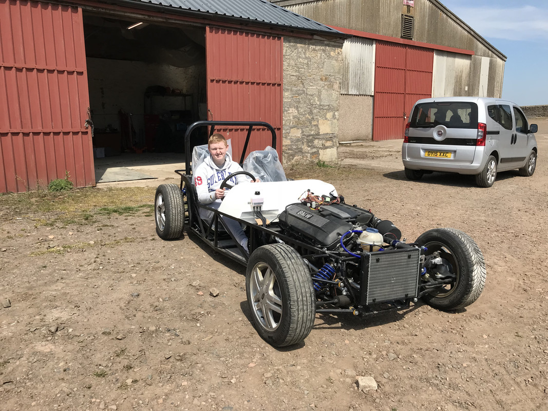
Great afternoons work, got front hubs fitted and wheels mounted - shocks arriving tomorrow from rally design.
Rear bulkhead fitted, awkward to get to the lower rivets but done now and silkaflex used to bond it to chassis.
Anyone found black cloth like used in the interior of lamborginis?

And seatbelt eyebolts fitted with assistance from forum member adithorp.

Drivers side tunnel panel fabricated with a little TLC fettling with the precision sheet metal adjustment tool ;-)

[Edited on 31/8/17 by craigdiver]
Been busy over the last couple of days. I had ordered material that was supposed to be similar to the stuff on the interior of lamborginis but
didn't like it so bought black (anthracite) cord carpet from carpetright for £2.99/sqm. Glued onto my rear bulkhead and drivers tunnel panel -
really happy with the finish. Fitted tunnel panel with M5 rivnuts and stainless countersunk hex screws with solid cup washers - again delighted with
finished look. Fitted drivers seat and sat in the car making vroom vroom noises ;-)
Next job was to assemble fuel pump, level sender, fuel return & rollover vent valve. Went ok but needing to work out how to secure BMW fuel pump
in tank, might need to buy aftermarket submersible pump that can be cable tied in internally.
I am about to buy a modified ECU which does away with; the BMW EWS security, after cats lambdas, limp mode. Also increases power to almost 200bhp. And
I wanted to prove engine was running ok with standard ECU before getting new ECU and heavily butchering the wiring loom.
Next job was to pull out the original BMW wiring loom to hook up and attempt to start the engine. Took ages to untangle it and find the connectors.
Connected all the negative points. Fuel pump not firing on ignition power up so hooked up a seperate power supply and tested. Good fuel rail pressure.
Turned engine over for a while but wouldn't even attempt to fire. Running out of time I pulled the plugs in case got fuel in the cylinders.
Next I'll pull engine fault codes and post on BMW forum to get some help to find the issue(s). Strange that the fuel pump isn't being run
for a few seconds on ignition.
Finally I sanded down the mk2 escort rack, painted & fitted. Need to measure up what extensions I need.


Bit rough but runs with heavily butchered loom & modified ECU. It stalled after giving it a bit of revs, please see post in ‘engine &
transmission’ if you have any thoughts.
https://youtu.be/sMSArNFT5rA
Feeling happy!
Amongst other jobs today on the car was to get samples from the BMW & sierra driveshafts so I could get sleeves made up to join them. The sierra
drive shaft is a serious piece of solid bar and the BMW drive shaft is a 2.8mm wall tube, guess what? the sierra driveshaft is an interference fit
into the bore of the BMW driveshaft - HAPPY DAYS! :-)
On a side note; I have discovered that wasps don’t like being sprayed with WD40 ;-)
[Edited on 7/10/17 by craigdiver]
quote:
Originally posted by craigdiver
Amongst other jobs today on the car was to get samples from the BMW & sierra driveshafts so I could get sleeves made up to join them. The sierra drive shaft is a serious piece of solid bar and the BMW drive shaft is a 2.8mm wall tube, guess what? the sierra driveshaft is an interference fit into the bore of the BMW driveshaft - HAPPY DAYS! :-)
On a side note; I have discovered that wasps don’t like being sprayed with WD40 ;-)
[Edited on 7/10/17 by craigdiver]

just picked up custom made GRP scuttle to fit my haynes/442E hybrid chassis, just need some warmer weather to get cracking on with the build.
Many thanks to forum user Hugh Paterson for all his hard work making a scuttle from my mock-up, would recommend him for any GRP you are needing for
your build whatever it is.
Happy new year to everyone following my build :-)
[Edited on 31/12/17 by craigdiver]
got drive shaft drilled for speedo magnet and painted. Also test fitted scuttle to make sure had clearance between bonnet line and engine and yipee
(and relief!) have 1-2” clearance. wont quite get a supercharger on there but at least engine won’t be rattling off the bonnet :-)


Some more progress despite the freezing temperatures. Driveshafts welded up, rear suspension assembled and brakes built up. Handbrake cables fitted.
Also got rear arch temporarily fitted to check fit and all good (I think!)


nearside rear drum brake assembled - quite tricky to get the new springs on but got there. Also got final bits of cooling system assembled (was
waiting on fabricated & painted brackets drying - took ages in the freezing temperatures- must get myself a little oven to bake parts when
painted).
Radiator looking a bit small compared to original one from donor but expect to have to replace it. 120W fan fitted on engine side of radiator to pull
air through.
Getting closer by the day to be able to drive it about the yard. Going to get my son to help replace the bushes in the front wishbones at the weekend
- this will allow me to finalise the front suspension and get the car on its wheels for the first time :-)


i’ve also ordered a 600mm length of 80mm ID silicone hose to move the air intake forward of the radiator to allow a cool air flow.
Lots of progress made yesterday and today;
- front suspension and steering completed (then swapped calipers as had them on wrong sides - bleed nipples below inlets!)
- hydraulic clutch test connected to see if clutch operating ok - had a pig of a job bleeding circuit but eventually got it filled with fluid but ran
out of brake fluid. Clutch pedal doesn’t feel great and not releasing clutch - hope it just needs bled properly and is not seized.
- cut opening in nose cone and made template for grille (any suggestions on what to use for grille?)
- fitted nosecone by hinging at the bottom and securing with couple of countersunk screws in the sides (will they be ok for IVA or do I temporarily
stick in a couple of bolts with plastic dome covers?)
- started reworking fuel tank pump/sender arrangement. Just need to get a bit of aluminium TIG welding done by a friend and then I can complete the
fuel tank - side note; used rubber gaskets previously - they had gone gloopy with the petrol fumes alone - glad I dismantled it or this would have
resulted in petrol vapour leaking. Replaced with cork gasket.


The fasteners on the nose cone. .Can't you.put them on the inside lip so they can't be seen ?.
That's how I did mine anyways.
Car lowered onto its wheels for the very first time (and workshop tidied). Running 115mm chassis clearance at the front and 130mm at the rear - looks
great, still smiling like a cheshire cat! I have 75mm clearance from sump to road so will be stiffening front suspension up (by compressing the coil
over springs with big c spanner?)

yipee - engine running - had mega issues getting it going but traced to huge vacuum leak from crankcase breather. Now just to free up the clutch and I can drive it round the farm :-)
Great news! much left to finish it?
Jay
quote:
Originally posted by J666AYP
Great news! much left to finish it?
Jay
Ouch, having the bodywork issue myself. Will deal with that some other time lol.
And spring 2019 is not a bad target, plenty of shakedown and tweaking time before the IVA. Sadly my one will take atleast another 2 years 
Jay
quote:
Originally posted by J666AYP
Ouch, having the bodywork issue myself. Will deal with that some other time lol.
And spring 2019 is not a bad target, plenty of shakedown and tweaking time before the IVA. Sadly my one will take atleast another 2 years
Jay
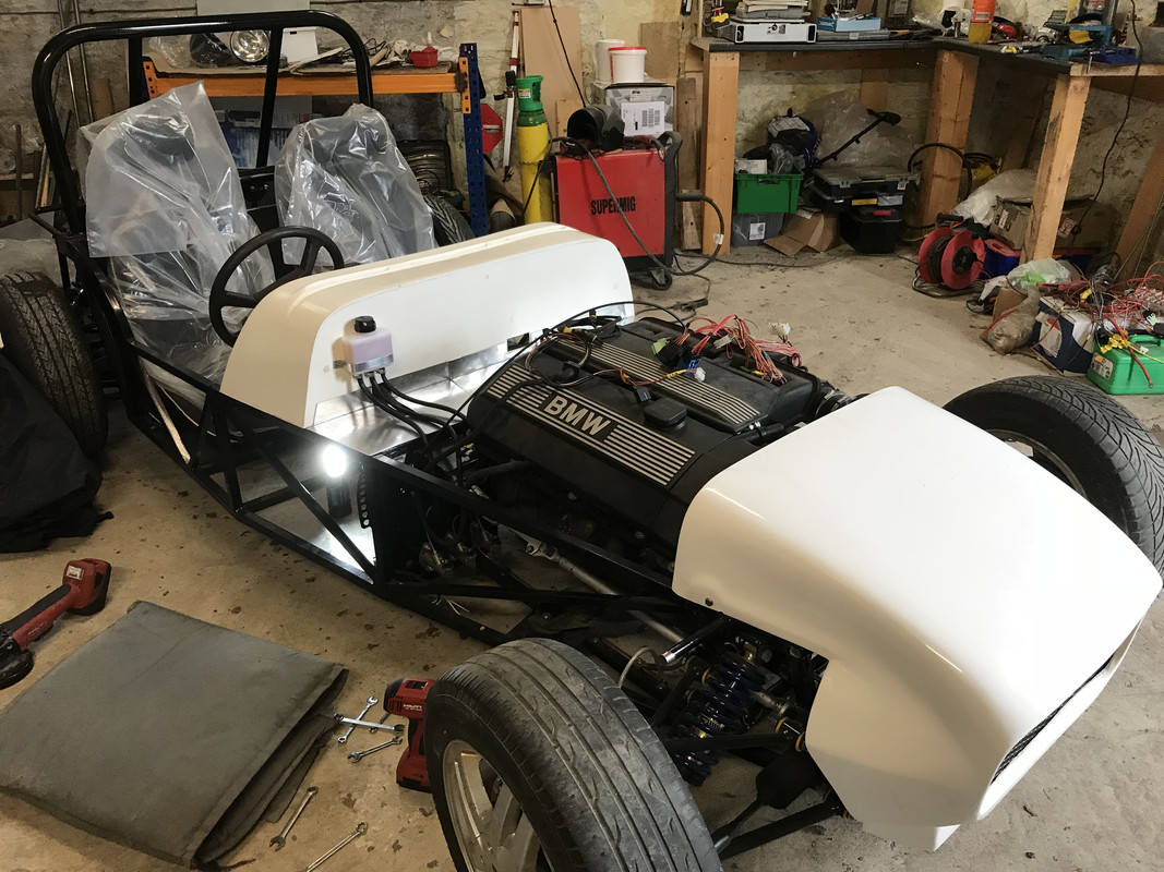
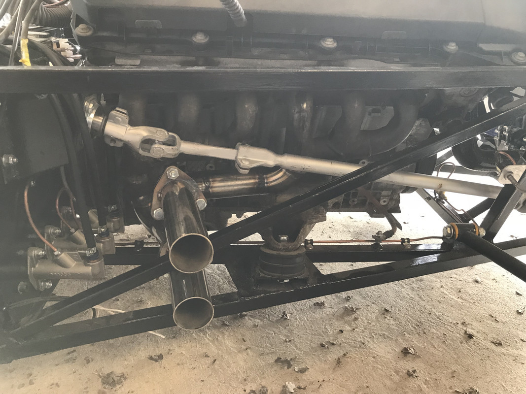
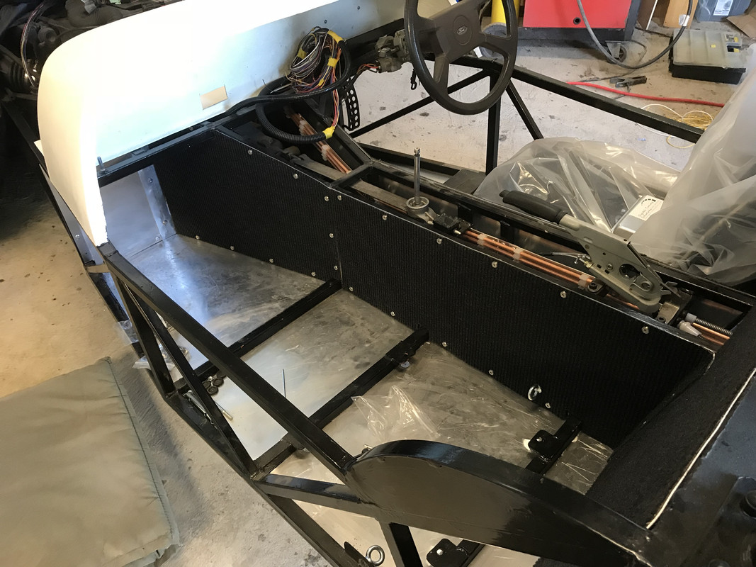
Quite a bit of progress made on electrical system / harness. Interior passengers side and bulkhead complete. made in 2 sections so could be removed
for easy access to gearbox / prop / clutch slave.
Thats looking tasty.
Good work there mate
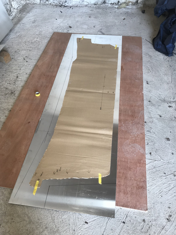
Been busy with the build the last few weeks and onto another milestone - starting to fabricate and fit the bodywork.
A bit of CAD (Cardboard aided design!)
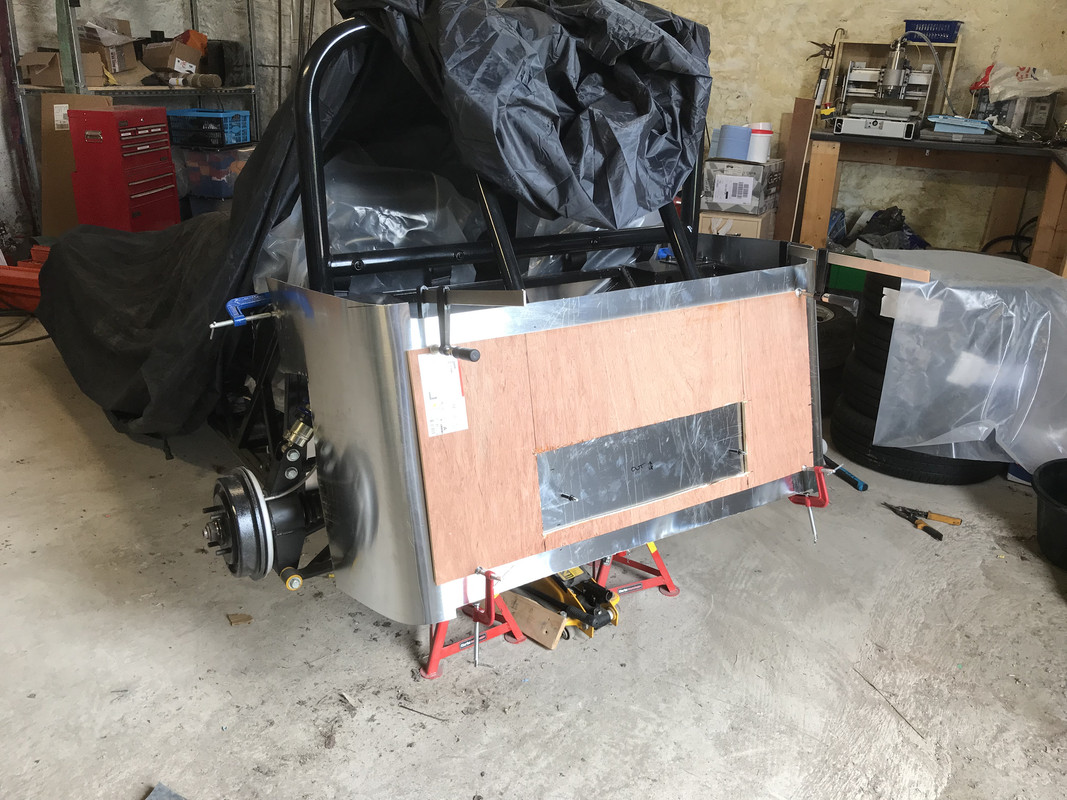
First fit - lots of work to do yet to get it to right shape - wood clamped on to hold it flat whilst working the aluminium.
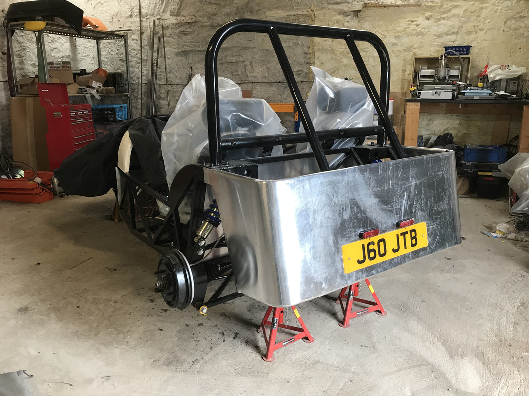
Rear tub finished, don’t thing ill take up metalworking for a living but pleasantly surprised at results!
Bonded on with silkaflex 221 and formed round upper and lower rear tub supports. Folded and rivited at D11.
Had to fit LED numberplate lights / reflectors before fitting panel as almost impossible to get into the rear of them due to fuel tank. (that will be
fun if I ever have to replace them!)
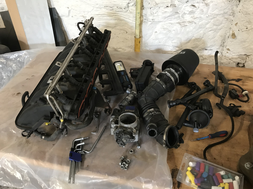
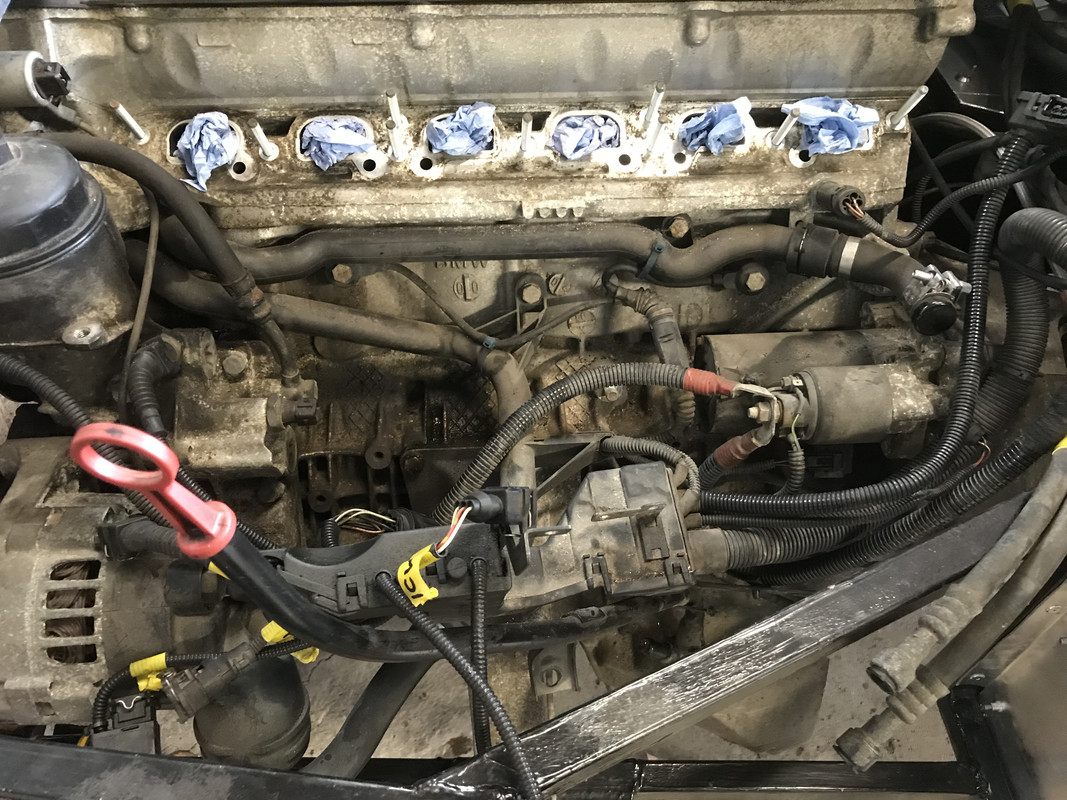
In between fitting the rear tub I have been working to diagnose an air leak causing rough idle. Eventually bit the bullet and whipped the inlet
manifold off. Found perished hoses from CCV to FPR and CCV to dipstick. The hoses were like putty and broke very easily - hopefully that was my issue.
Have ordered complete CCV kit which comes with complete set of vacuum hoses. Also took the opportunity to remove both the purge valve and secondary
air pump valve which are no longer needed.
[Edited on 29/7/18 by craigdiver]
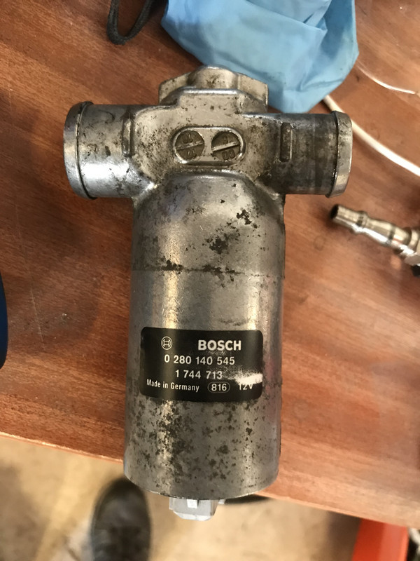
Started testing the sensors and actuators before refitting them to the inlet manifold. Looked on youtube on how to test the ICV (Idle Control Valve)
and on turning it back and forth it should rattle - mine doesn’t. Hit it with half a can of carb cleaner until I felt it starting to free up then
rattle freely. Hopefully this was the rough idle issue. Will be reassembling everything tomorrow so fingers crossed.
so far had inlet manifold off and checked seals, fitted new CCV and pipework, fitted 'good' used idle control valve, changed MAF for
'good' used one. smoke tested for vacuum leaks. unplug MAF and it idles ok but higher revs. plug in the MAF and it idles like this...
(engine is M52TU)
I have INPA if anyone can suggest any tests?
https://youtu.be/tEx3HvMpO40
It sounds like Idle speed correction is overshooting its adjustments....
quote:
Originally posted by craigdiver
so far had inlet manifold off and checked seals, fitted new CCV and pipework, fitted 'good' used idle control valve, changed MAF for 'good' used one. smoke tested for vacuum leaks. unplug MAF and it idles ok but higher revs. plug in the MAF and it idles like this... (engine is M52TU)
I have INPA if anyone can suggest any tests?
https://youtu.be/tEx3HvMpO40
some positive news (I think!). decided to remove intake rubbers so I could see what the throttle body & idle control valve were up to with MAF
disconnected. See video below, all seems to be working well. Whats not on the video is that I put my thumb over the inlet to the ICV and engine
immediately stalled with no hissing from anywhere - i'm sure now that any air leaks have been fixed. everything seems to be pointing to a faulty
MAF. My only concern is that I have bought another second hand MAF and it doesn't idle with that either. Have I been unlucky and now have two
duff MAFs?
(is it only me that thinks its cool the ICF is synced electronically with the TB?)
https://youtu.be/I7Thaz3nqas
gave up for the evening but ill take a look at what INPA is reading off the MAF with ignition on then i'll disconnect MAF so engine idles,
connect up supply from battery to MAF and then measure the signal, think should get roughly 1-4v from idle to high revs.
Any other test suggestions? unfortunately engine won't idle or rev with MAF plugged in so cannot read values off INPA
quote:
Originally posted by craigdiver
some positive news (I think!). decided to remove intake rubbers so I could see what the throttle body & idle control valve were up to with MAF disconnected. See video below, all seems to be working well. Whats not on the video is that I put my thumb over the inlet to the ICV and engine immediately stalled with no hissing from anywhere - i'm sure now that any air leaks have been fixed. everything seems to be pointing to a faulty MAF. My only concern is that I have bought another second hand MAF and it doesn't idle with that either. Have I been unlucky and now have two duff MAFs?
(is it only me that thinks its cool the ICF is synced electronically with the TB?)
https://youtu.be/I7Thaz3nqas
gave up for the evening but ill take a look at what INPA is reading off the MAF with ignition on then i'll disconnect MAF so engine idles, connect up supply from battery to MAF and then measure the signal, think should get roughly 1-4v from idle to high revs.
Any other test suggestions? unfortunately engine won't idle or rev with MAF plugged in so cannot read values off INPA
quote:
Originally posted by rodgling
If you do end up getting another MAF, I would recommend biting the bullet and getting one from your local BMW dealer, it'll be expensive but it will work.
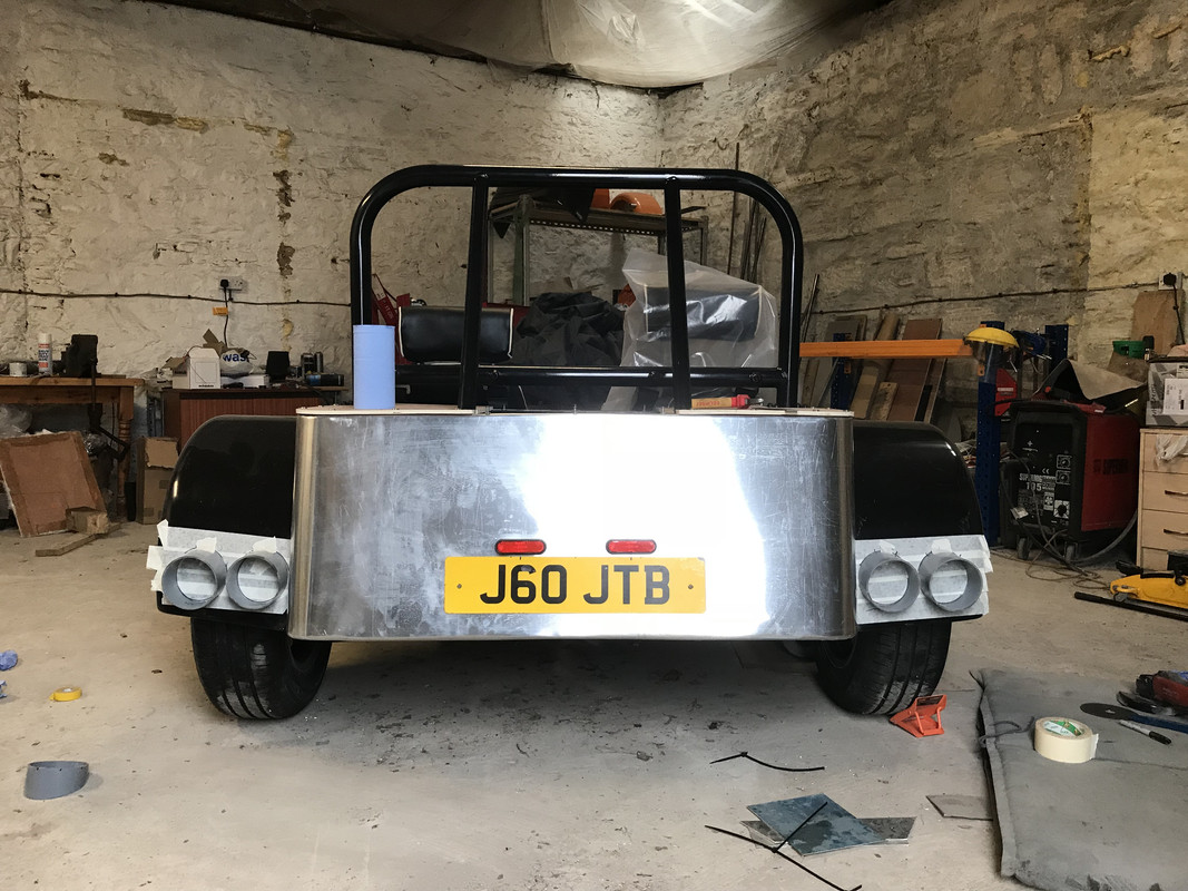
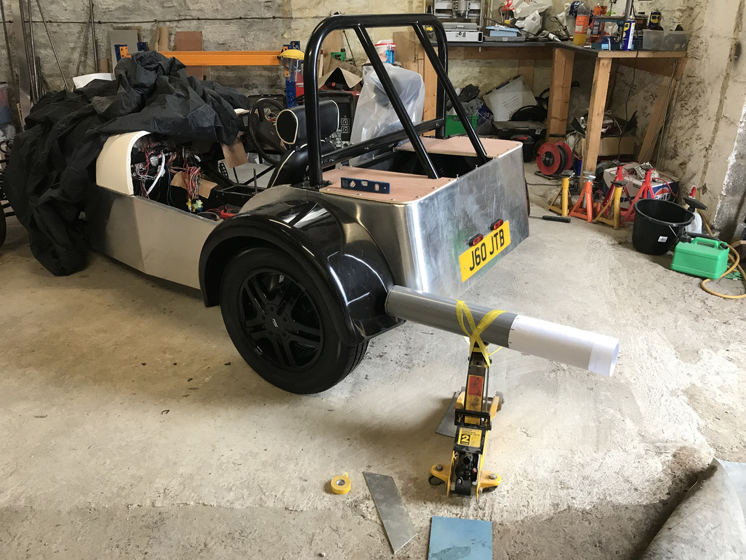
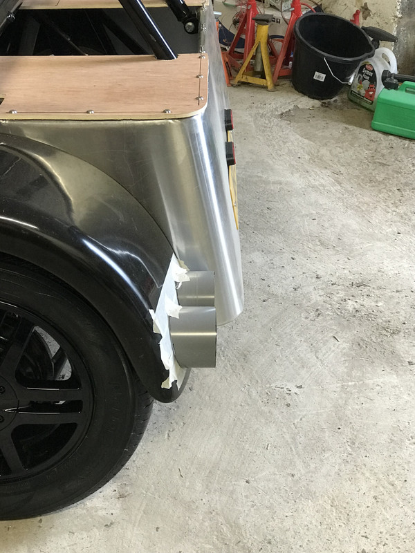
fabricated rear pods for my rear lights out of a bit of drainage pipe. Quite tricky to profile to the compound curves on the rear arches but got
there. managed to get the true on both axis so Mr IVA should be happy with my fog being at the right angle. Just got to paint them black, remove my
shiny new wheels so I don’t drill into them, and fit lights - happy days

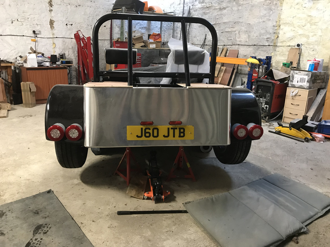
Rear lights fitted but will need to fit a fog light on my rear panel for the IVA as don’t have 100mm separation between brake and fog lights. As per
photo below the four lights have a side-light halo, outer lights have indicator and brake, inner lights have both fog and reverse. Was just planning
on using fog on O/S and reverse on N/S. going to paint grey pipe pods black and cover with neoprene rubber as bit of an edge on the back of the light
units.
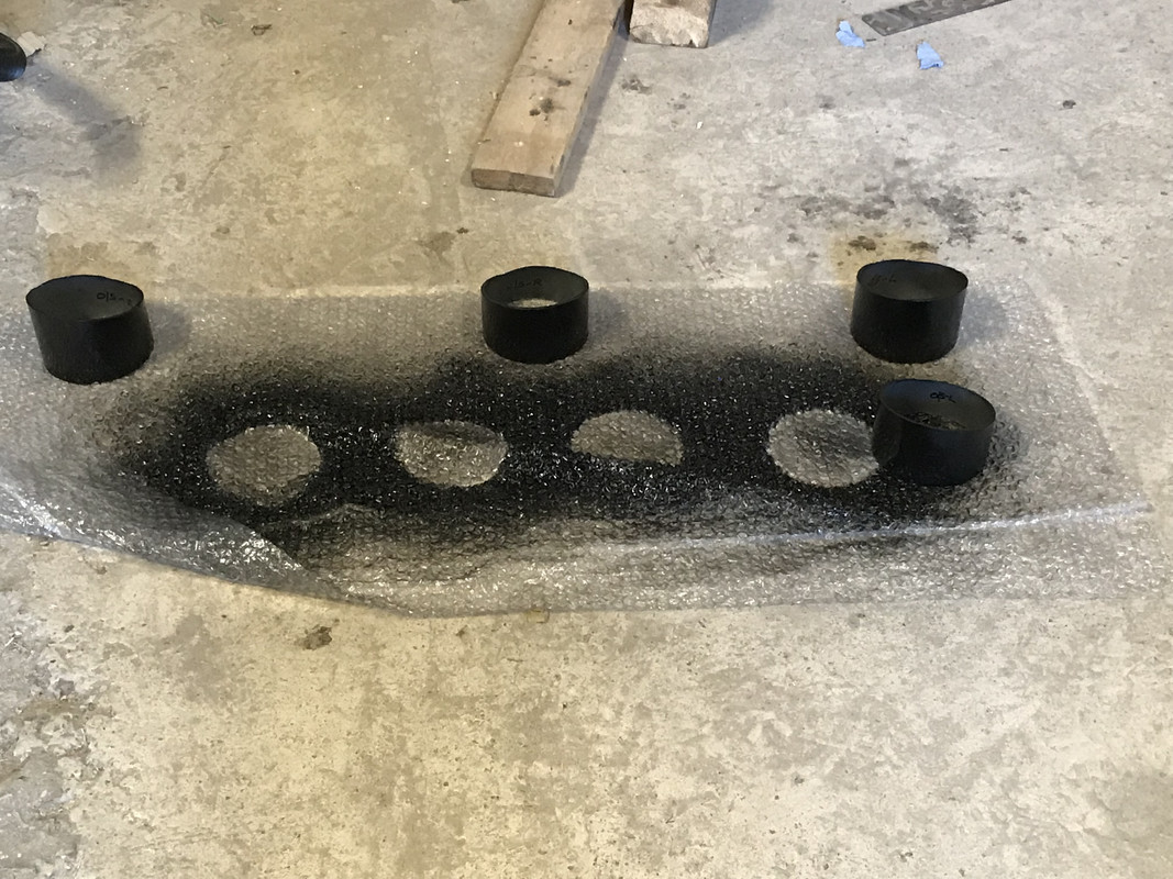
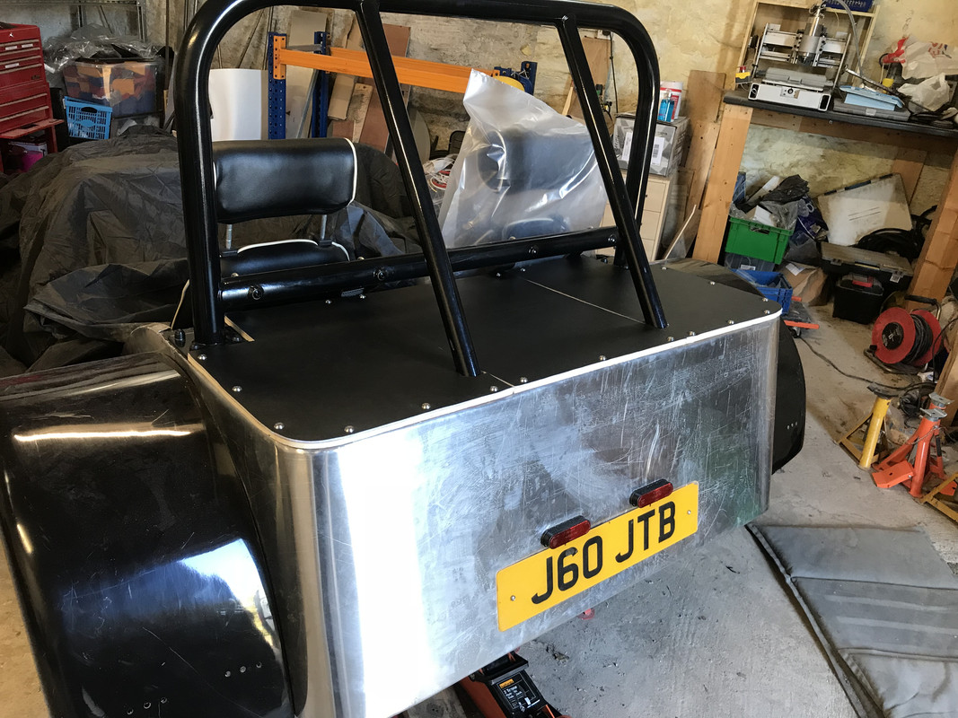
rear tub cover attempt no.2 done and happy with the result. Just need to find some black rubber trim to finish the edge off. Also got lighting pods
painted.
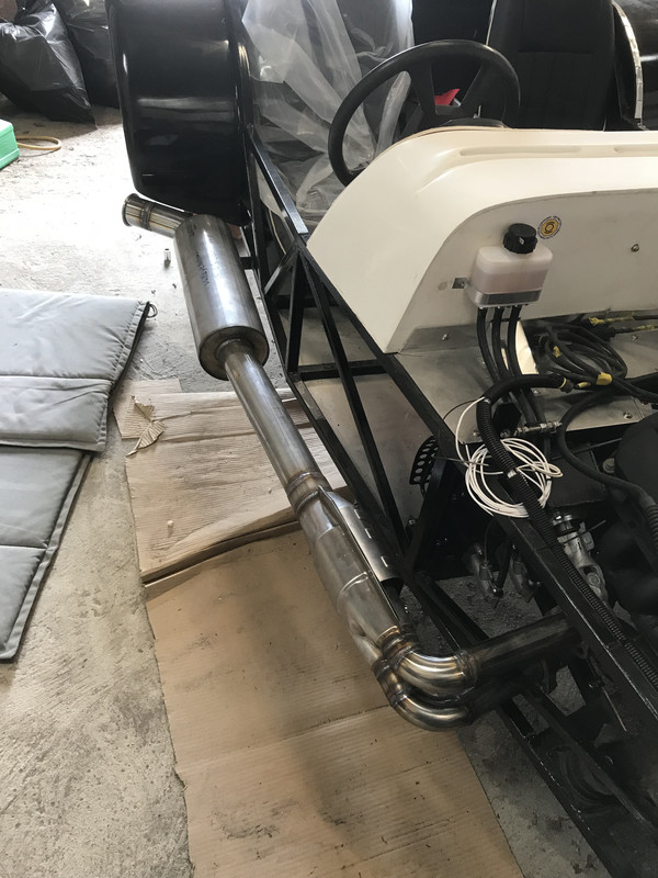
Thats my exhaust welded up today and it sounds amazing. I have left a gap on the 3” pipe to fit a clamp on 12” silencer if it is too loud for IVA but
actually doesn’t sound too bad. The rolled tail pipe protrudes around an inch wider than my rear arch, is that ok?
Will be going to a metal polisher to get brightened up, any ideas how I can make the seams of the silencer IVA friendly (CAT will be completely
wrapped in exhaust wrap so will be ok)
quote:
Originally posted by craigdiver
... any ideas how I can make the seams of the silencer IVA friendly (CAT will be completely wrapped in exhaust wrap so will be ok)

quote:
Originally posted by Angel Acevedo
quote:
Originally posted by craigdiver
... any ideas how I can make the seams of the silencer IVA friendly (CAT will be completely wrapped in exhaust wrap so will be ok)
There´s a thread where someone request ideas to modify a bike can.
The can has a riveted on shroud that covers these seams.
After giving it some thought I think ill roll a bit of perforated material and secure it with pipe clamps on either side of the silencer. I’ll be able to finish the edges of the perforated sheet with safe-edge edging.
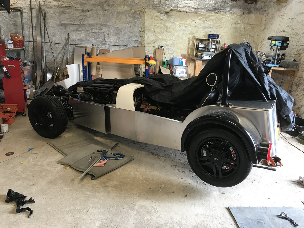
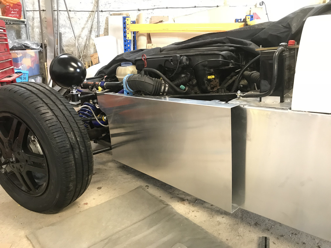
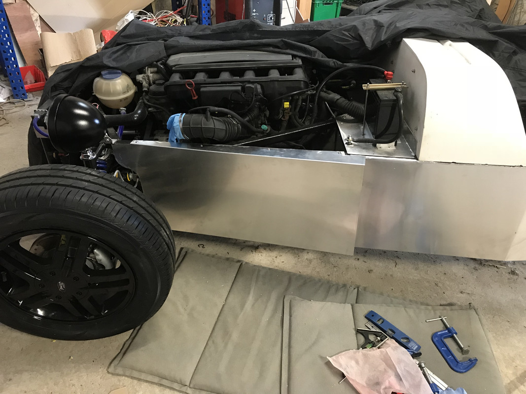
craigdiver - 21/8/18 at 09:13 PMGetting very near getting the car into the spray booth for spraying aluminium panels white to match the scuttle and nose cone.
near side now complete, just got front off-side panel to fabricate then its strip down mask it up and paint!
craigdiver - 21/8/18 at 09:17 PMOnce painted ill fill the seam between the aluminium panels and scuttle with white silkaflex 221.
Any suggestions for making a finishing trim for the cockpit side rails? (think I may have asked this already)
Angel Acevedo - 22/8/18 at 02:13 PMquote:
Originally posted by craigdiver
Once painted ill fill the seam between the aluminium panels and scuttle with white silkaflex 221.
Any suggestions for making a finishing trim for the cockpit side rails? (think I may have asked this already)
At some point in time I had a small piece of thin (2 mm or so) diamond ali plate that I planned to use as steps.
Was planning to use on the B2 Tubes also...
craigdiver - 22/8/18 at 02:47 PMWow - 25,000+ views. I really do hope others are getting something out of this build log. 2 years into the build and a massive thanks to all of you hope contributed some knowledge and wisdom.
craigdiver - 22/8/18 at 07:21 PMAnother productive evening, final panel (O/S front) fabricated. The front panels have been designed to be removable as in the future I want to drop an M3 lump in and engine access is tight from above. The tops of the panels are mounted with rivnuts. I didn’t want to drill the bottom rail to insert rivnuts so fabricated brackets which I welded onto the chassis to secure the bottom of the panel. masked off the bottom of the panel and sprayed paint through the brackets to mark where to drill the holes in the panel for mounting. Getting very near painting time.
craigdiver - 22/8/18 at 08:37 PMGoing to be getting ready to spray paint the body of the car. I have a full respirator suitable for 1K & 2K paints. Access to a spray booth tent. I have bought 1K white etch primer and 2K paint which has been matched to my scuttle and nosecone colour (by magic at the automotive paints place by them scanning the colour from a piece of gel coated GRP from my nose cone).
The bodywork panels are all new semi-hard aluminium and were plastic film coated until I fabricated them into the body panels.
I have never spray painted before with compressor / spray gun so have done quite a bit of research and have come up with this process; (please advise if i’m doing something wrong)
1) going to degrease body panels
2) machine sand panels with 320 grit
3) clean and degrease panels
4) mix my white etch primer with 15% thinners as instructed by paint manufacturer.
5) spray only one coat and let dry for 24 hours.
6) ** do I sand it down before first coat of top coat, if so, with what grit?
7) mix 2K paint 2:1 10% ratio/thinners and apply first coat.
8) ** do I sand it down before next coat of top coat, if so, with what grit?
9) will I need to give it more than one top coat, if so, spray second coat.
Fingers crossed that all goes well!
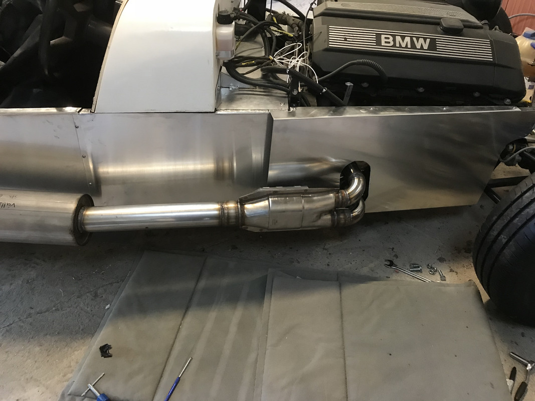
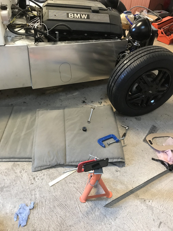
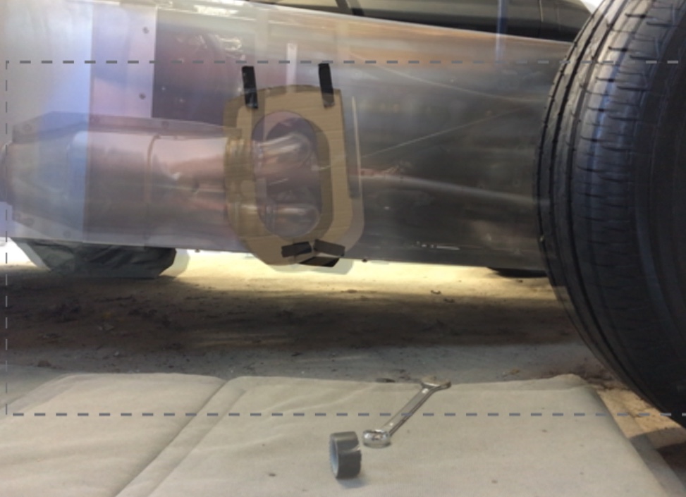
craigdiver - 23/8/18 at 07:07 PMFront O/S panel folded and fabricated. Needed to cut hole for exhaust. well, job done and I was bricking it - It took ages to get that panel just right and now I have to cut a big hole in it for the exhaust. Thank you for your everyones advice to make a cardboard template - but never took it (on this occasion). I went down the technology route and used an app that allowed me to superimpose a photo onto the current camera image. So after making a cardboard template of the hole shape;
1) set camera up in a fixed position.
2) fit exhaust and take initial image.
3) remove exhaust and fit panel.
4) superimpose previous image and mark hole - cannot go wrong as can see ghost image of exhaust.
5) cut hole with perfect result
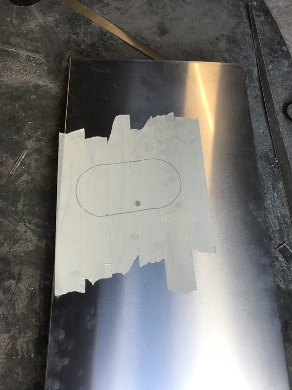
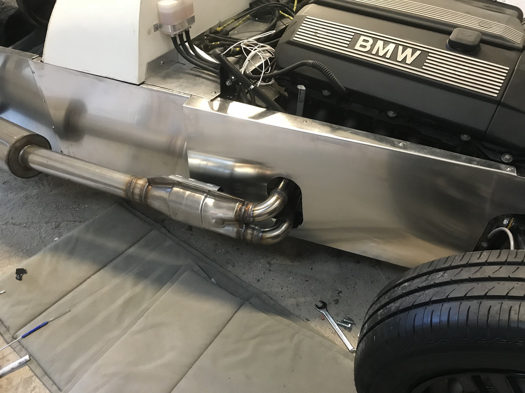
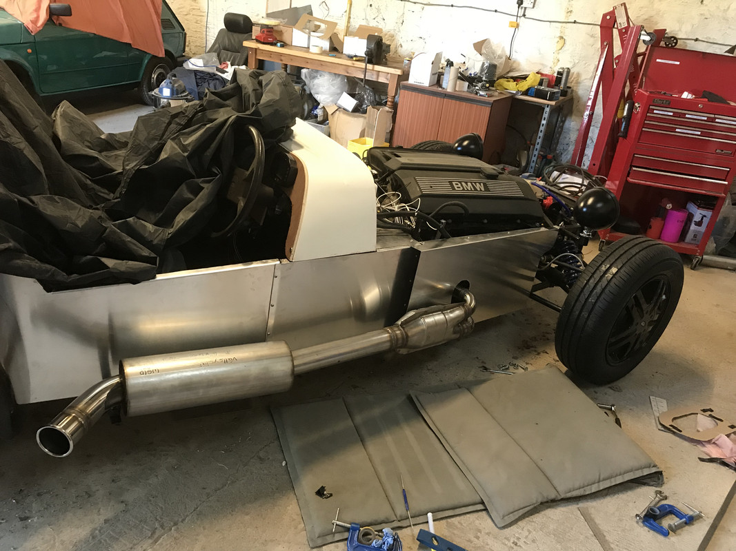
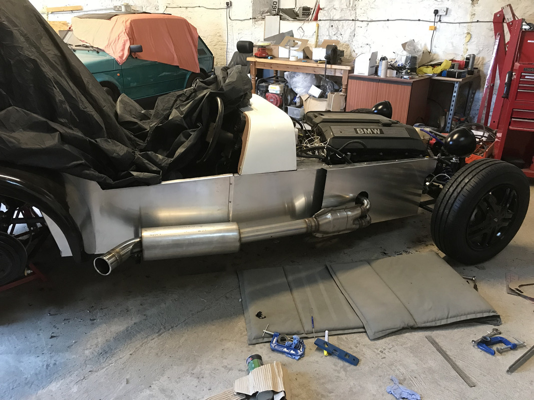
[Edited on 23/8/18 by craigdiver]
[Edited on 23/8/18 by craigdiver]
craigdiver - 24/8/18 at 02:02 PMSo, engine not running well with MAF connected (was working when I drove donor to my workshop two years ago) so bought a used but ‘apparently’ good MAF to diagnose issue - guess what, didn’t help. Learned how MAFs work and diagnosed the two MAFs I have and no signal from either. Bought a new cheapish MAF at £30. Arrived and engine now very smooth and purring like a Rottweiler. Now I know it was faulty MAFs would you order and fit the £160 BMW OEM MAF?
Angel Acevedo - 24/8/18 at 02:21 PMquote:
Originally posted by craigdiver
So, engine not running well with MAF connected (was working when I drove donor to my workshop two years ago) so bought a used but ‘apparently’ good MAF to diagnose issue - guess what, didn’t help. Learned how MAFs work and diagnosed the two MAFs I have and no signal from either. Bought a new cheapish MAF at £30. Arrived and engine now very smooth and purring like a Rottweiler. Now I know it was faulty MAFs would you order and fit the £160 BMW OEM MAF?
I´d run the 30 quid one and when it packs up, i´d change...
craigdiver - 24/8/18 at 07:11 PMNow engine running great, couldn’t help getting it out for it’s first drive...
https://youtu.be/9lAnPd8rnaM
craigdiver - 9/9/18 at 02:39 PMHad quite an ordeal painting the car but now done and ready for final assembly.
Painting ordeal can be found here; http://www.locostbuilders.co.uk/forum/4/viewthread.php?tid=213218
craigdiver - 9/9/18 at 02:56 PMWhile i’m waiting for myself to get my finger out and finish the roadster I treated myself to this.....
It’s an absolute hooligan to drive!
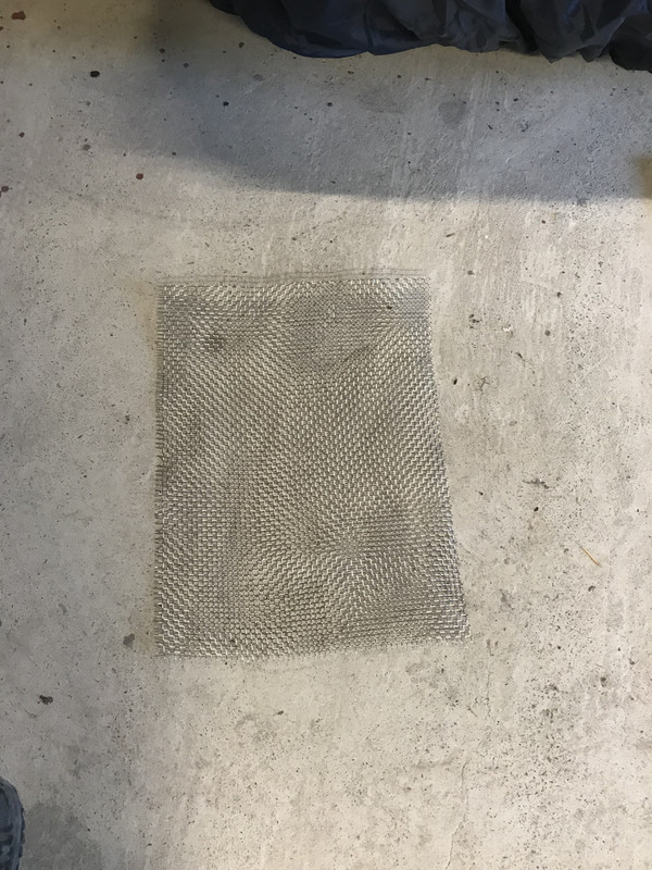
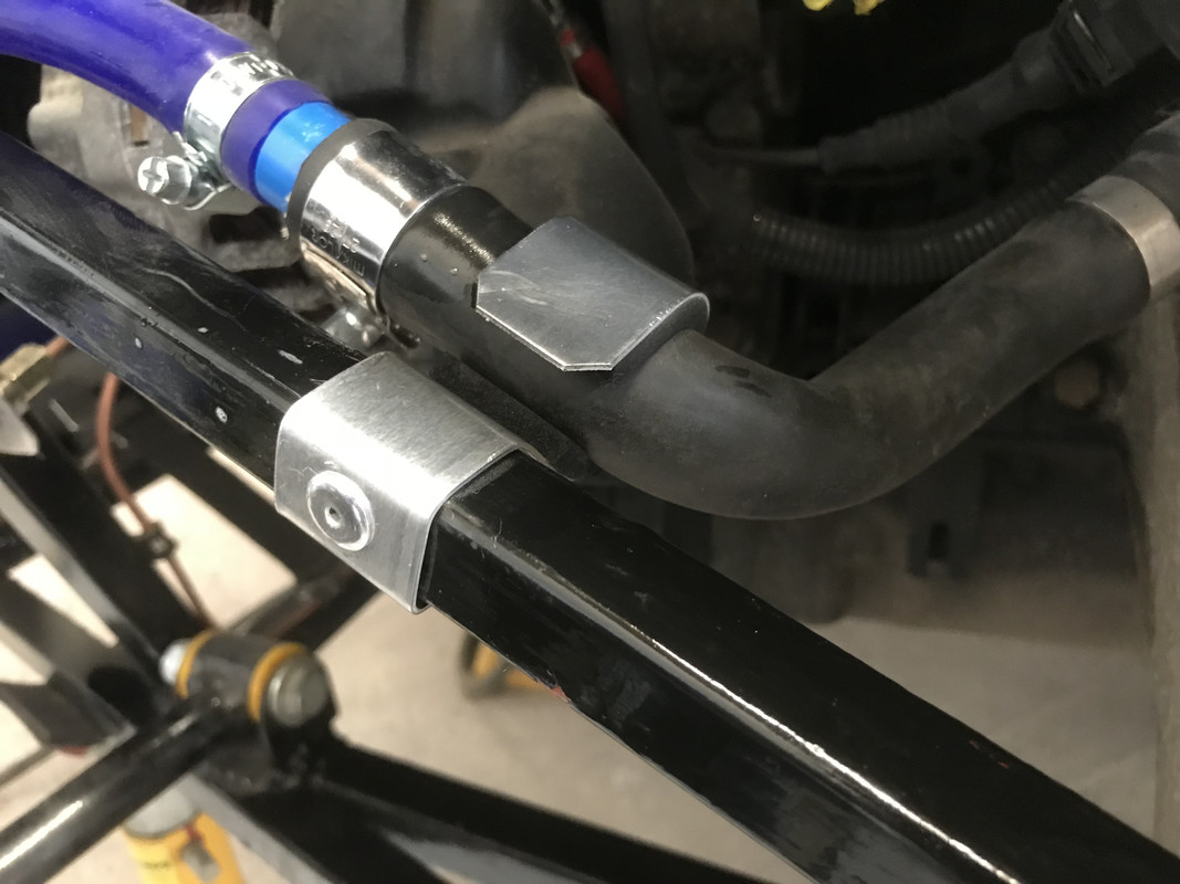
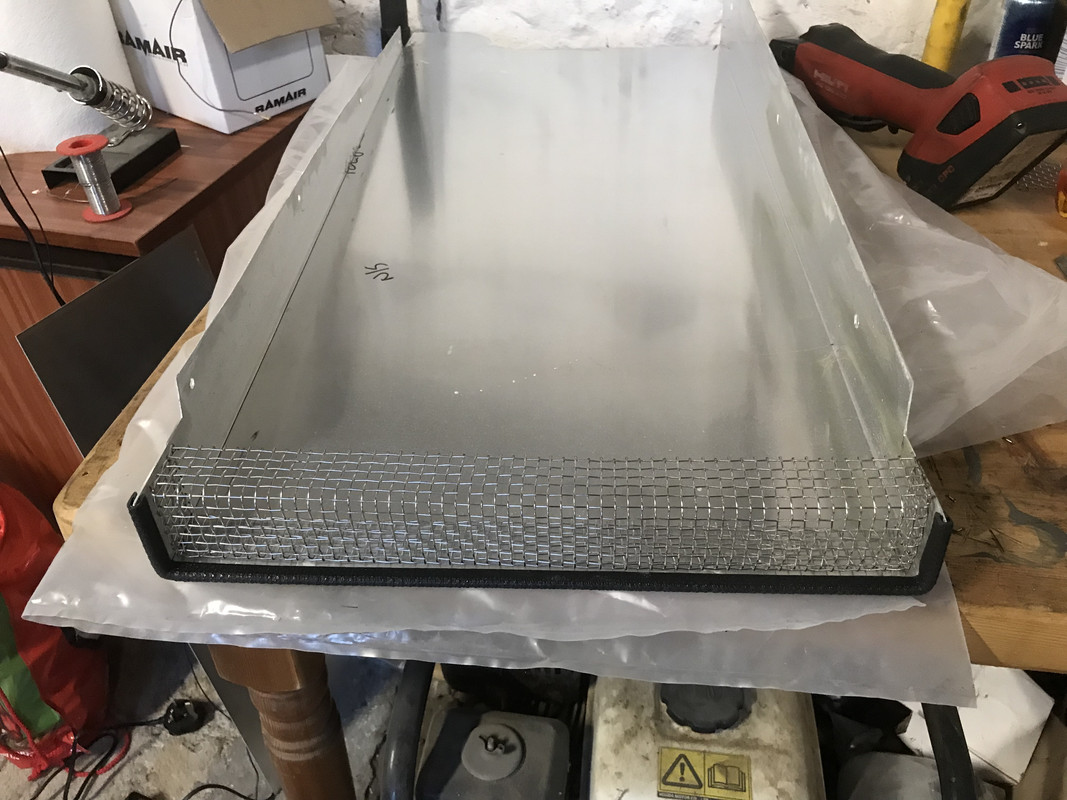
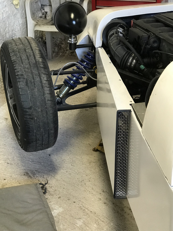
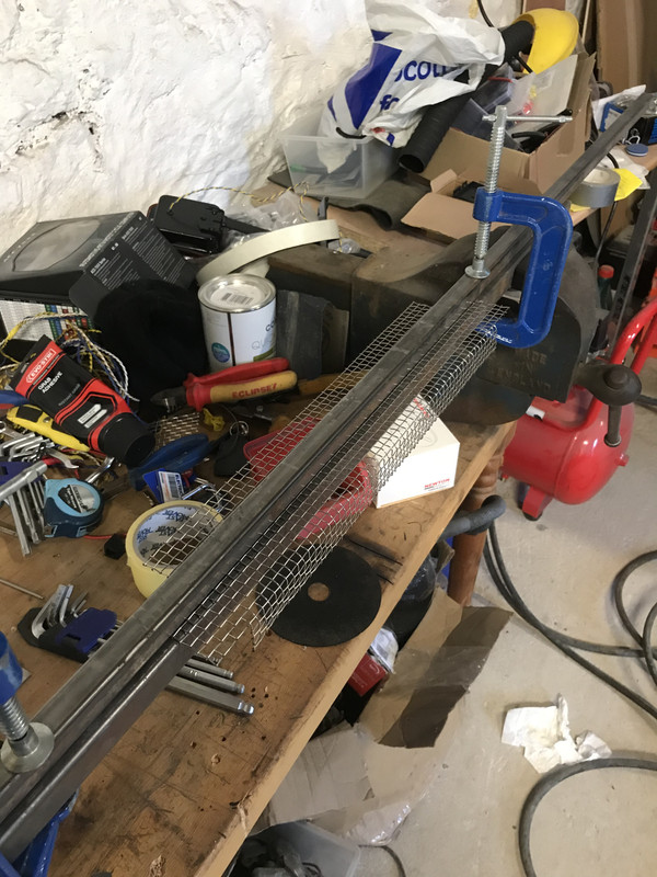
craigdiver - 15/9/18 at 10:14 AMStarted on getting N/S engine panel bolted on. Fabricated side grilles from stainless mesh and hot glued into position. Fabricated bracket to secure cooling pipe at side of engine. Went to test fit panel to see where I needed to put safe-edge on the leading edge and found I had painted the bottom of it rather than the top - complete muppet! sanded down and brush painted, actually looking not too bad. Ill post a pic when paint dry and panel fitted.
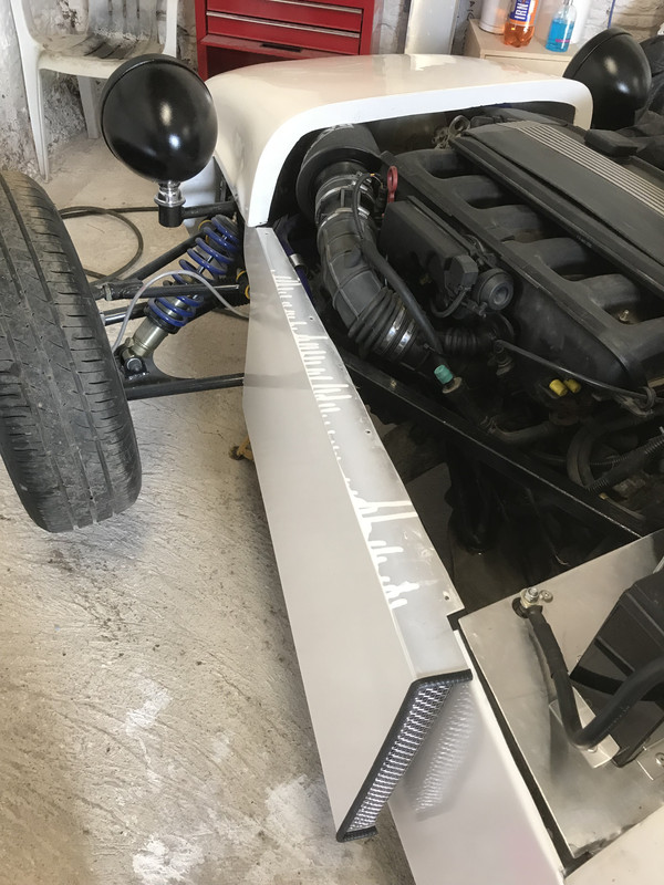
craigdiver - 15/9/18 at 12:25 PMFront N/S panel fitted - really pleased with the result. Paint-job questionable but has the built it myself look!
Angel Acevedo - 18/9/18 at 03:12 AMquote:
Originally posted by craigdiver
Started on getting N/S engine panel bolted on. Fabricated side grilles from stainless mesh and hot...

At some point in time my engine bay sides will have the same arrangements, but I haven´t thought about grilles there.
What is the reasoning to install them?
Thanks.
AA
craigdiver - 20/9/18 at 02:04 PMHi Angel, purely cosmetic
quote:
Originally posted by Angel Acevedo
quote:
Originally posted by craigdiver
Started on getting N/S engine panel bolted on. Fabricated side grilles from stainless mesh and hot...
At some point in time my engine bay sides will have the same arrangements, but I haven´t thought about grilles there.
What is the reasoning to install them?
Thanks.
AA
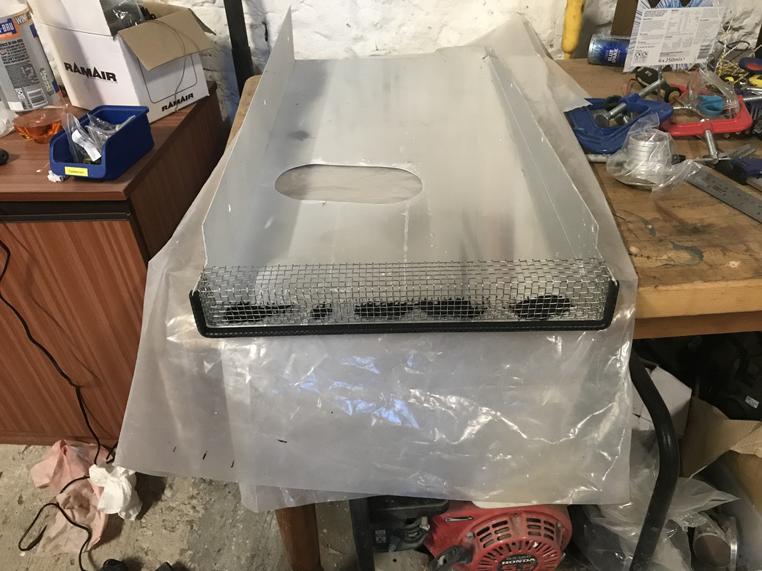
craigdiver - 4/10/18 at 07:40 PMGot a little bit more done this evening, got clips silkaflexed onto inside of rear tub to support rear wiring harness and fabricated grille for O/S front panel.
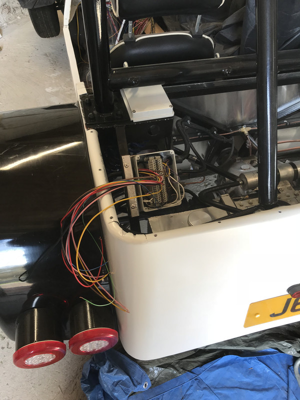
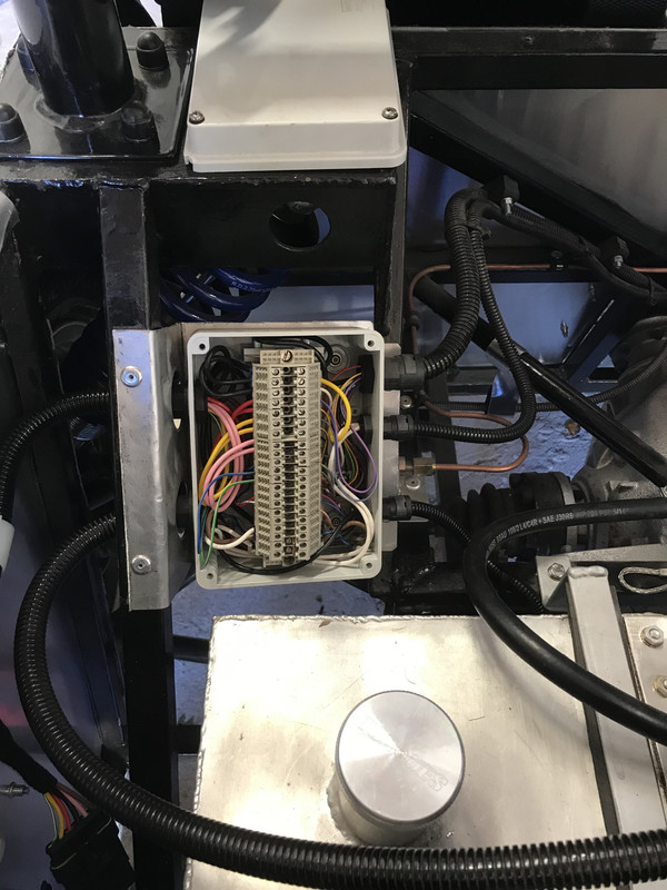
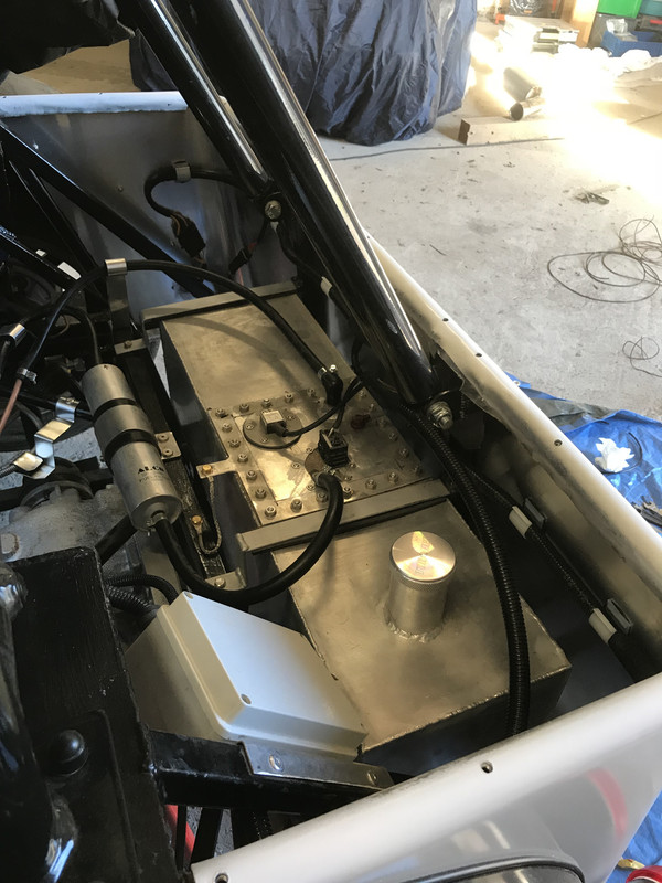
craigdiver - 6/10/18 at 01:00 PMThat is the rear loom fabricated, tested and installed. I have had to add a secondary fog light as the fog lights in my combined units are too close to the brake lights. For show use only, the fog light unbolts easily and a link put in the connector and the fog lights work in the combined units. All lighting circuits have been taken back to the dash as I intend to control lights through a microprocessor so that I can have some fancy effects / strobing rear lights (again for show use only!). I’ll probably add in an accelerometer so that the hazards / brake lights flash quickly if I brake realy hard.


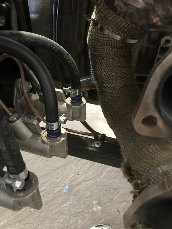
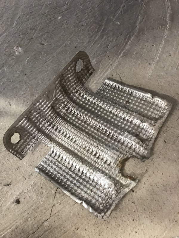
craigdiver - 6/10/18 at 01:40 PMI wasn’t too happy with the proximity of the exhaust to the clutch master cylinder so I adapted a heat shield that I found in a layby a few months ago (funny how you spot something and just know that will come in useful!). Fitted and happy now.
craigdiver - 7/10/18 at 11:57 AMA productive Sunday morning. Section 1 of 3 of rear tub hard cover painted and had trim glued on, fitted to car and pleased with the look. The main event this morning was machine polishing/buffing my freshly fabricated stainless steel exhaust. Used soapy water as lubricant and sanded with 400, 600, 1000, 1200, 1500 and finally 3000 grit. After a clean up with fresh water a whole tube of Autosol was buffed into it with a lambswool pad on the machine polisher. Not quite mirror finish but looks good. Actually pleased with the finish, highly polished mirror finish would be a bit too ‘classic’ for me. I already had a piece of aluminium cut and folded for the transmission tunnel cover. I made up a template for the handbrake hole and cut out with grinder and dressing edges with file. The hole for gearstick was cut with a holesaw. Think ill cover it with some padded black vinyl. Since everything going well I decided to have a go fitting the half-round aluminium profile to the passenger side cockpit edge. Didn’t have a countersink bit so my countersunk hex machine screws are sitting proud but will pick up bit and countersink holes.
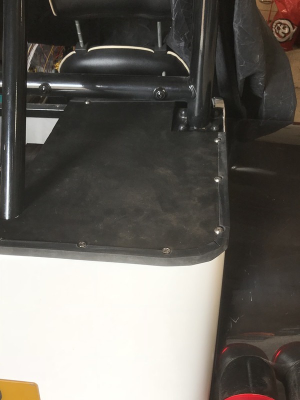
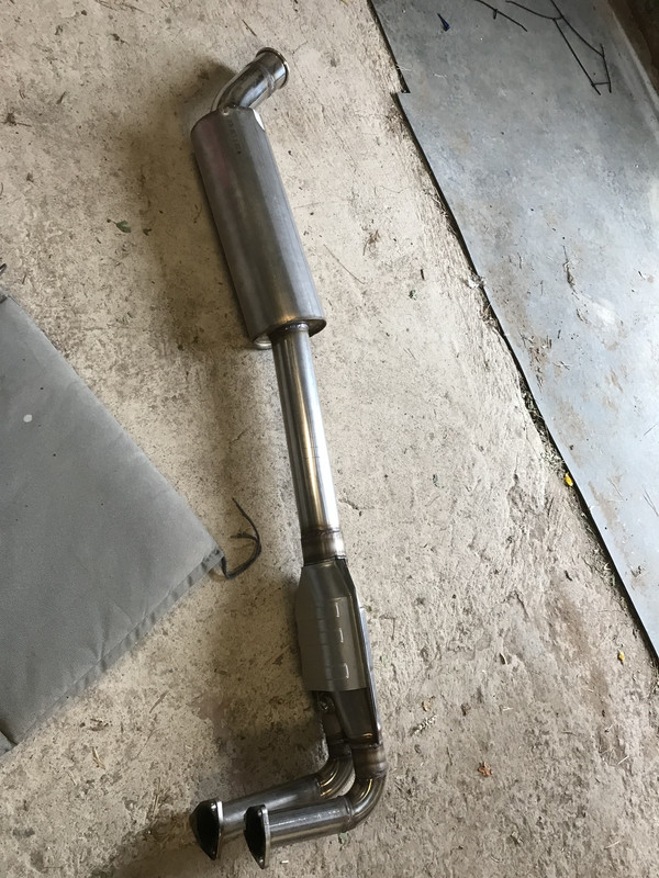

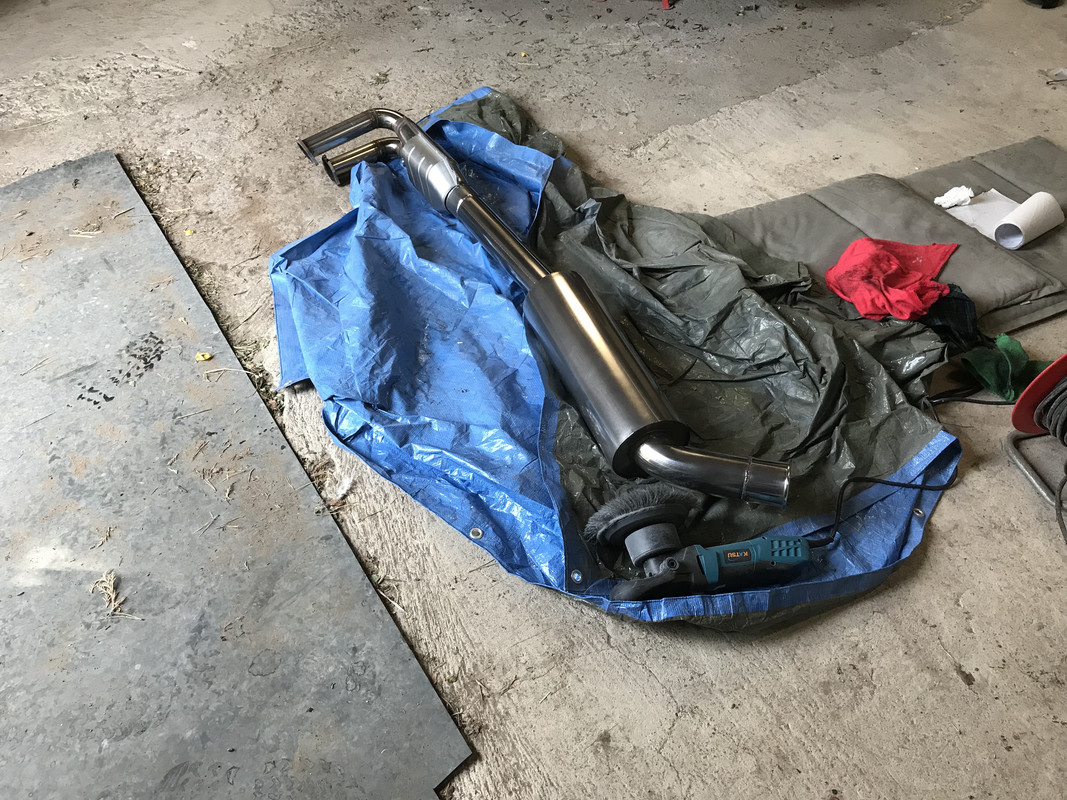

craigdiver - 15/10/18 at 05:42 PMHad a day off work today so got a few jobs done. Firstly dismantled brake pedal / bias bar assembly and fitted locking kits. Reassembled and added the obligatory ‘do not adjust blah blah’ sticker. This allowed me to fit side panels and the exhaust. Oh what fun connecting the exhaust to the downpipes, few war wounds later the exhaust is on. Next I got it off the axle stands and couldn’t help myself taking it for a spin round the yard (I can just feel it wants to go faster!). Next job was to fit the half-round aluminium trim on the drivers side cockpit edge. Finished off wiring brake light switch and reservoir level switch into loom and fabricated a couple of brackets to secure.
I’m acquiring some thin stainless sheet later this week that I intend to fabricate into a bonnet. Not decided whether to paint white or wrap with carbon fibre effect wrap.
Issues I had today is that the rear lights are only 335mm off the ground and need to be 350mm for IVA. Fortunately i’ve not set my rear coil-overs yet and should be able to raise car up 20mm (are lights measured with anyone sitting in the car?).
Also, will I need to cover the harness to eye connections?
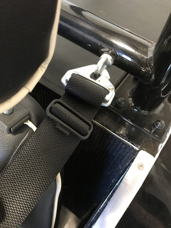

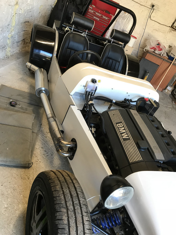
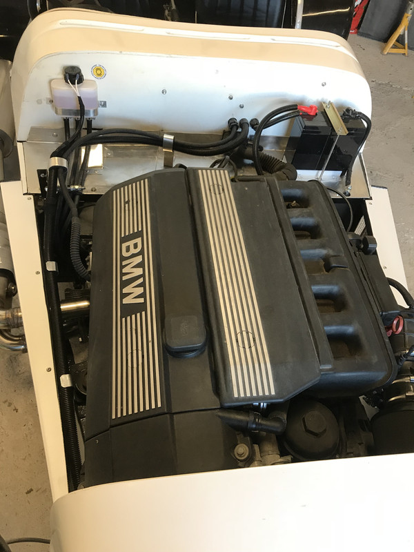
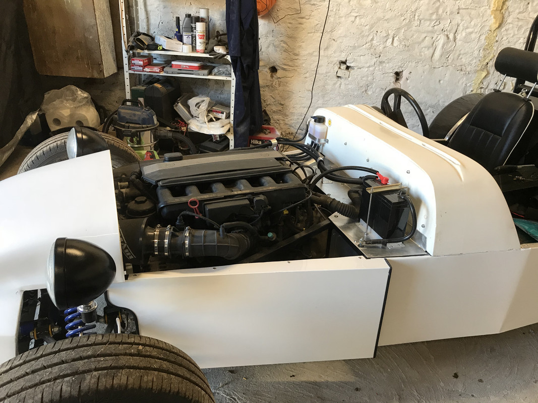

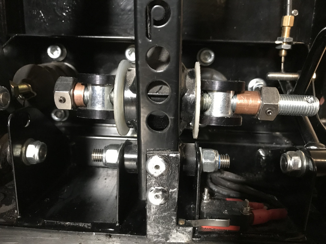
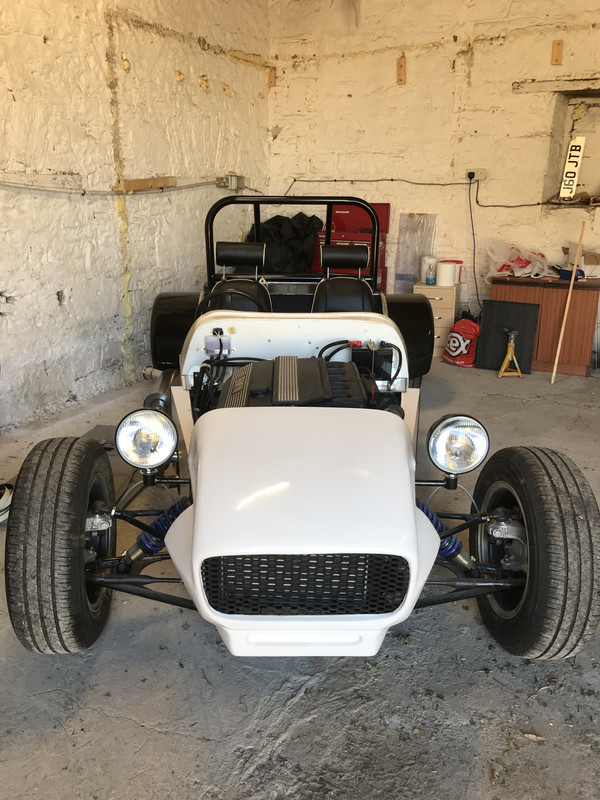
SJ - 15/10/18 at 06:36 PMLooks great - have to say your wiring is super neat and the engine bay looks amazingly uncluttered.
craigdiver - 15/10/18 at 07:47 PMquote:
Originally posted by SJ
Looks great - have to say your wiring is super neat and the engine bay looks amazingly uncluttered.
thank you, its a mix of OCD and being an electrical engineer!
craigdiver - 16/10/18 at 06:32 PMDid the last couple of jobs to complete rear end. Rear tub covers complete with trim. Also, rear fog light replaced with one with both ‘E’ and ‘F’ markings.
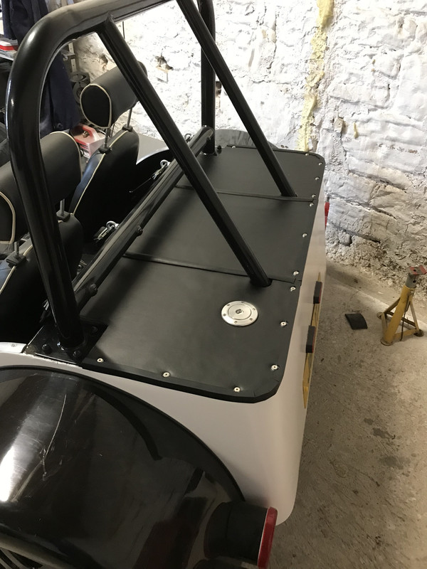
craigdiver - 21/10/18 at 02:09 PMA bit of electrical work today. Been working on a design for indicators & hazzard warning lights and set up on bench to test. Two live feeds, one switched from ignition, one permanent (for hazzards). 3 diodes, one electronic flasher relay and one DPST dashboard switch for hazzards. Also started on the electronics for microprocessor control of rear lights for special effects. I have also included an accelerometer to measure emergency braking which will flash hazzards quickly. The microprocessor will also control fog light function which will make the logic simple with any changes being a simple change to a few lines of code.
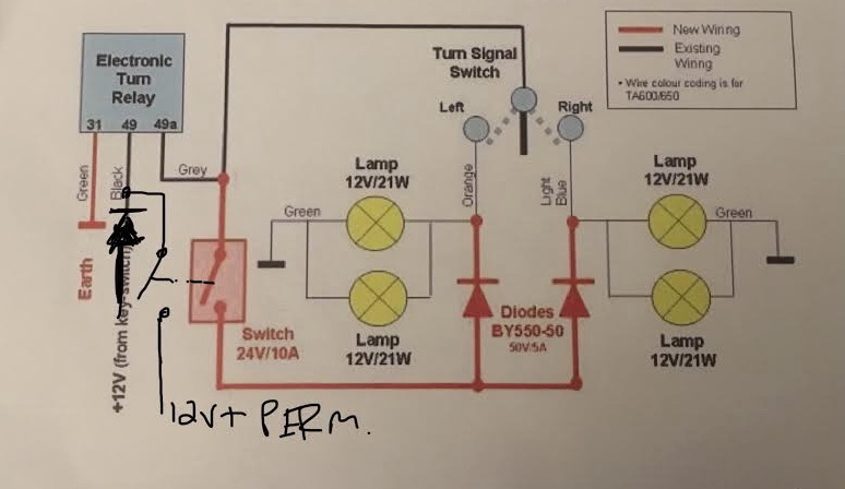
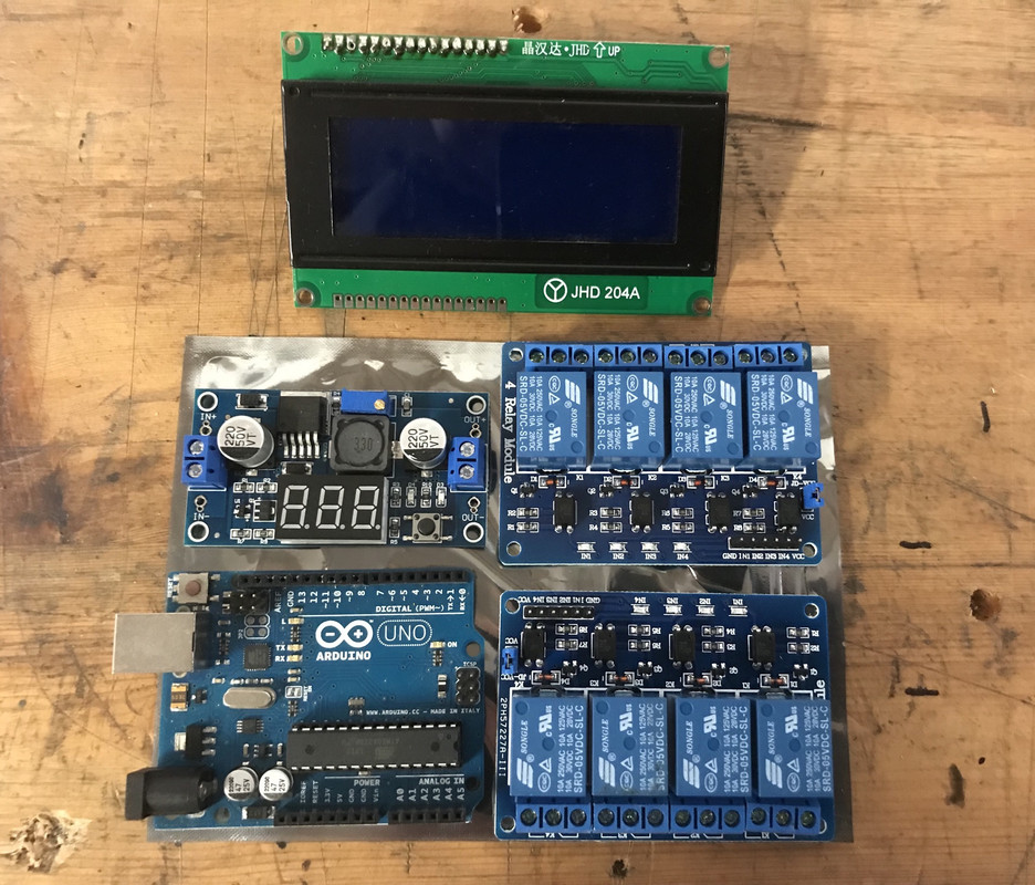
craigdiver - 21/10/18 at 02:12 PMAs a side note; I do not recommend complete microprocessor control of rear lights without some robust purpose built automotive system. I will be achieving fail-safe integrity by controling the lighting circuits through banks of n/c relay contacts. When the microprocessor wants to take control of the lights it will switch the relays and use high speed mosfet switching to perform the desired effects.
craigdiver - 25/10/18 at 01:54 PMAbout to start on the bonnet. Going to make 2 supports same shape as nose cone and scuttle from 4mm aluminium. I’ll join these using 4mm aluminium flat bar. This should give me a frame that I can use rollers to roll the bonnet to shape over the frame then weld* onto the frame (*have welded by a welder - wouldn’t attempt to weld aluminium myself)
craigdiver - 25/10/18 at 08:40 PMBonnet support ribs fabricated for scuttle and nose cone. Surprisingly easy to cut 4mm aluminium with jigsaw.
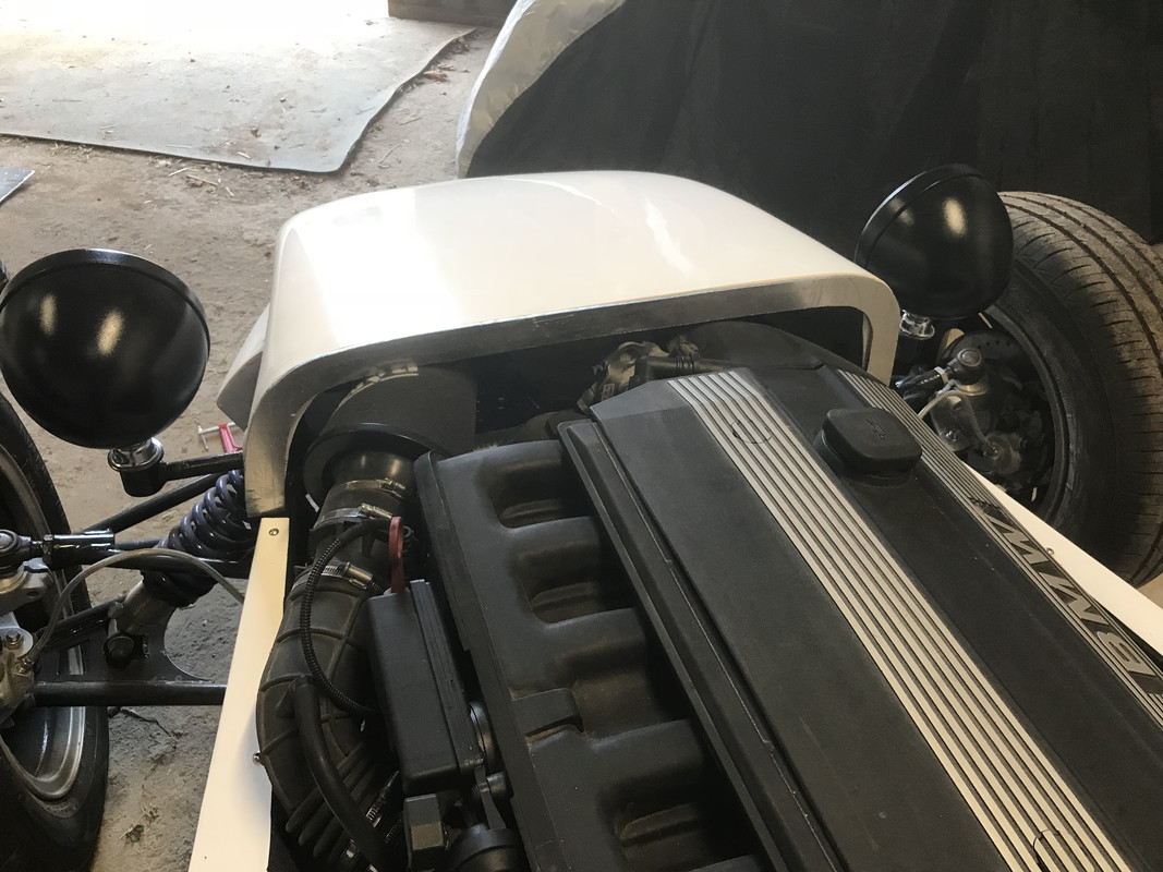
craigdiver - 27/10/18 at 04:51 PMMy son Matthew who is learning to drive couldn’t resist having a drive round the yard.
Angel Acevedo - 27/10/18 at 06:05 PMquote:
Originally posted by craigdiver
My son Matthew who is learning to drive couldn’t resist having a drive round the yard.
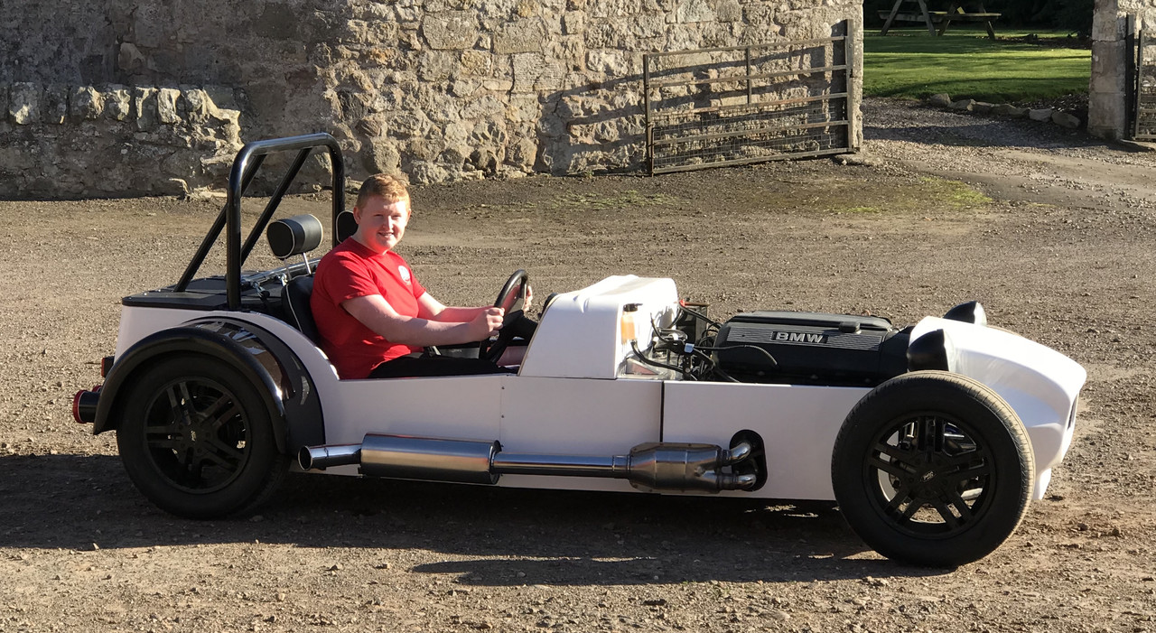
From this picture I think you´ll have problems to comply with Harness anchor points requirements.
Or do you have a plan already?
craigdiver - 27/10/18 at 06:58 PMquote:
Originally posted by Angel Acevedo
quote:
Originally posted by craigdiver
My son Matthew who is learning to drive couldn’t resist having a drive round the yard.
From this picture I think you´ll have problems to comply with Harness anchor points requirements.
Or do you have a plan already?
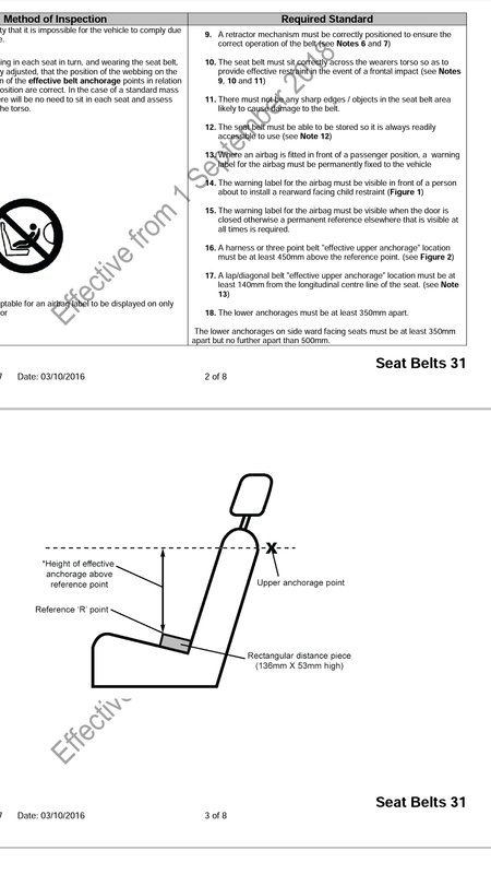
[Edited on 28/10/18 by craigdiver]
Angel Acevedo - 27/10/18 at 08:40 PMI´ve done some search and now I think that what I wrote it´s just hearsay.
Some manufacturers state Mininmum amd maximum "recommended" angles, but even then the angles beyond that are not listed as non acceptable.
Regards.
AA
craigdiver - 27/10/18 at 09:01 PMquote:
Originally posted by Angel Acevedo
I´ve done some search and now I think that what I wrote it´s just hearsay.
Some manufacturers state Mininmum amd maximum "recommended" angles, but even then the angles beyond that are not listed as non acceptable.
Regards.
AA
thanks Angel, I appreciate your advice
craigdiver - 28/10/18 at 11:25 AMAngel, you were right, my upper anchorages are only 400mm above the reference point (as per IVA manual), needs to be at least 450mm. Will need to rework the roll hoop and pay to have powder coated again :-(
Angel Acevedo - 28/10/18 at 02:21 PMquote:
Originally posted by craigdiver
Angel, you were right, my upper anchorages are only 400mm above the reference point (as per IVA manual), needs to be at least 450mm. Will need to rework the roll hoop and pay to have powder coated again :-(
Sad, but I think that´ll be cheaper than a re-test anyway isn´t it?
craigdiver - 29/10/18 at 05:32 PMI am guilty of not reading then re-reading the IVA manual and understanding it very well. I made the mistake where I never realises there are two sections relating to seatbelts and their anchorages. Fortunately, my mistake had a relatively straight forward fix. I had never planned my build so I could measure a reference minimum dimensions between seat base and upper anchorages. To rectify this I am removing the very thick seat squab and replacing it with something much thinner. This has an added bonus in making the seat back taller which may have been an issue.
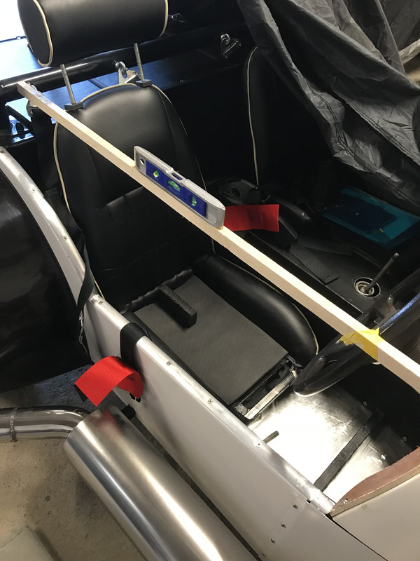
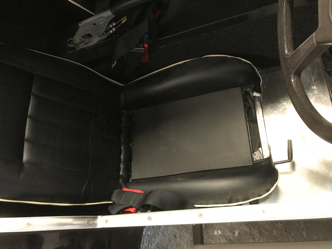
craigdiver - 24/11/18 at 10:45 AMWhen I originally assembled the coolant system I wasn’t entirely confident it wouldn’t leak so only filled it with water. Suffice to say - it never leaked! It was playing on my mind that it was getting cooler up here so decided was time to drain the water and fill with some decent quality (BMW approved) anti-freeze and summer coolant. Was happy to see the drained water completely clear and not a rusty colour (don’t know why as it is an alloy block, I just like worrying about things!). Now filled and engine run up to temperature :-)
craigdiver - 5/3/19 at 06:33 PMHi all, been busy over winter with my other hobbies, foreign travel and small Fiats, but now ready to get stuck back in about the car and get it ready for its IVA as the weather is warming up. Took it out for a blast round the yard at the weekend - still fun and very tail happy! Just ordered wing and rear view mirrors along with micro indicator repeaters for the front cycle wings.
First job is to get wiring finished off. Still no easy solution for a bonnet but have some aluminium I can form and see how it looks / fits.
I’ll update with pics soon.
craigdiver - 9/3/19 at 06:47 PMlong shift on the car today. Job today was to connect up all the wiring looms for lighting, dashboard switched, fuse and relay box. Everything went very well (surprised my indicators / hazzard lights circuit worked). Last job was to hook up the neg. switched reverse gearbox switch to a relay to switch reverse lights. Due to quality chinese moulded relay box, the very last terminal refusing to go into its terminal position - getting frustrated at it so will tool down and attack it another day. Once wiring loomed ill take some pics.
craigdiver - 5/4/19 at 10:45 AMBeen putting this job off as not sure how to form the supports accurately or what clearances I should use. Any advice very welcome. (Will be painted black to match rear arches - white / black / orange colour scheme probably bit too much!)
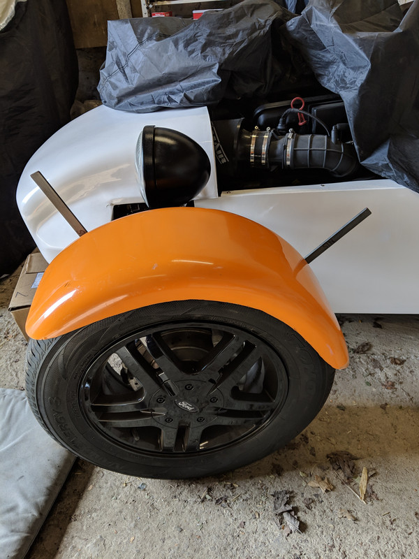
[Edited on 5/4/19 by craigdiver]
craigdiver - 5/4/19 at 02:07 PMWell that wasn't too bad, bracket off and on a dozen times but looking and sitting not too bad. Now the other side to do. Need to drill holes to mount side repeaters then remove them to paint brackets and wheel arches black.
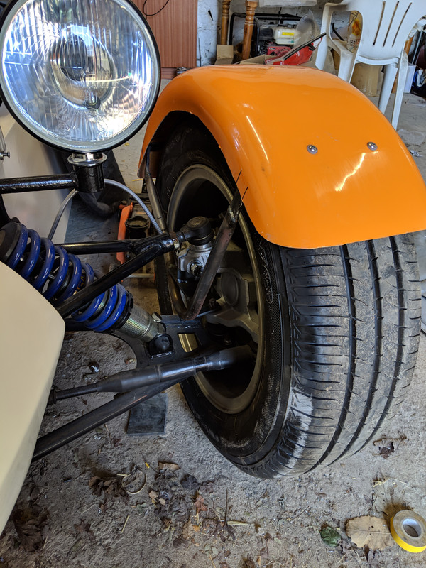
craigdiver - 6/4/19 at 02:12 PMWas nothing to worry about at all, relatively straightforward, however, don't think I should give up my day job to become a metal-worker! Going to remove them now and paint brackets and arches black.
craigdiver - 19/4/19 at 11:28 AMMaking the most of the warmer weather and getting my cycle wing stays and wings sanded and primed
craigdiver - 19/5/19 at 02:27 PMFinished the last wiring job today - wiring up O/S headlight unit and fitting and wiring both front indicators and side repeaters. Really pleased with the results and within dimensional spec. for IVA.
(Indicator extensions will most definitely fall off after IVA!)
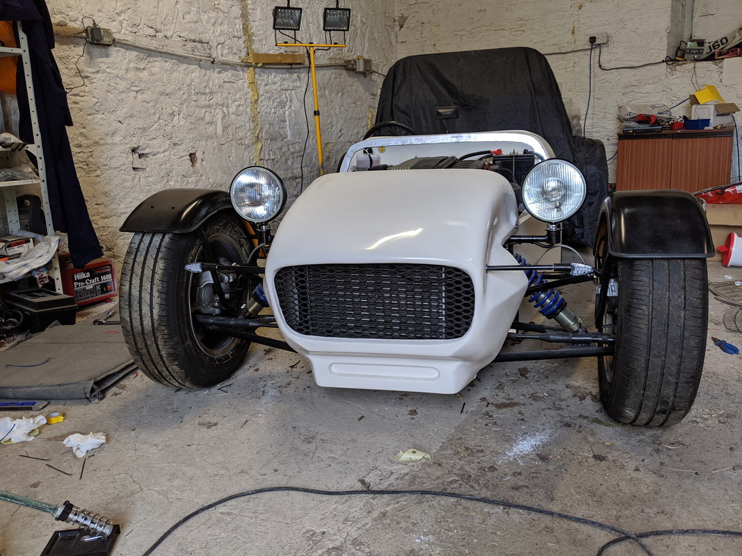
CTLeeds - 22/5/19 at 03:36 PMWell done Craig, it's really coming along.
How far away from IVA do you think you are? I only ask as if you're getting close it might be worth putting a call into the DVSA to see what the current lead time is at your nearest centre. In March at Beverley (my nearest test centre) the guys said after April lead times for appointments started creeping up to nearly 6 - 8 weeks!
Keep up the good work!
Regards
Chris
craigdiver - 27/5/19 at 10:57 AMHi Chris, sorry never seen your reply earlier. Great advice, I live in Fife, Scotland and have no idea yet where my nearest IVA centre is! I work away from home and have to do bits and pieces when I get the opportunity. In no real rush, would like to get it on the road but probably going to be later on in the year and having it ready to go for next summer.
Cheers
Craig
quote:
Originally posted by CTLeeds
Well done Craig, it's really coming along.
How far away from IVA do you think you are? I only ask as if you're getting close it might be worth putting a call into the DVSA to see what the current lead time is at your nearest centre. In March at Beverley (my nearest test centre) the guys said after April lead times for appointments started creeping up to nearly 6 - 8 weeks!
Keep up the good work!
Regards
Chris
craigdiver - 27/5/19 at 11:03 AMElectrics done and now onto bonnet. Roughly have an idea how this will go together but will definitely be making it up as I go along! Firstly as neither my nose cone or scuttle has and bonnet support lips I am having to fabricate something myself. I have cut aluminium supports slightly smaller than the profiles on the nose cone and scuttle. I then cut some rubber and sandwiched it. Nose cone done and pleased with the result. Scuttle next which will be trickier as the majority of my wiring is under there. Once that is done I'll make a bonnet template using polythene and cut out of sheet aluminium.
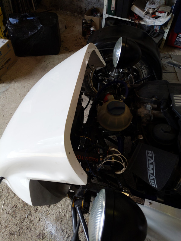

craigdiver - 27/6/19 at 05:56 PMBit more work this afternoon on sorting out a custom aluminium bonnet. Support made from aluminium and rubber and fixed onto scuttle.
Got polythene sheet to use to make a template for cutting the aluminium to size prior to bending it into shape.
Got a concern about the wiring for the side repeaters on my cycle wings. Run it through kopex trunking and cable tied onto wishbones. Not sure Mr IVA will like this but cannot see any other way to do it. Any suggestions? Or should that be ok?

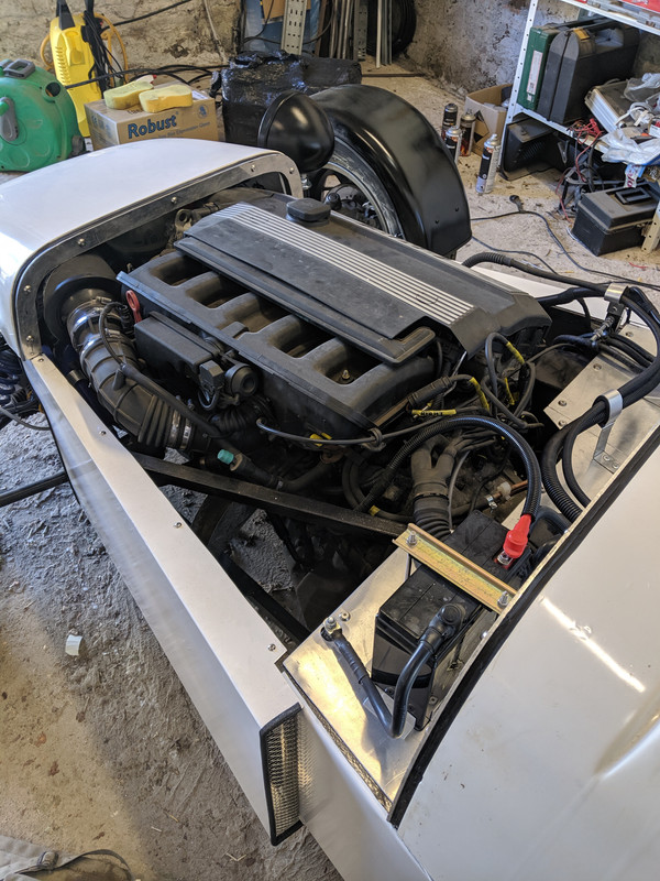
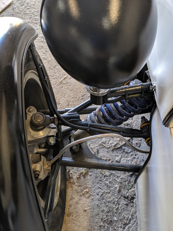
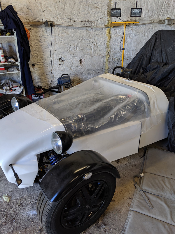
[Edited on 27/6/19 by craigdiver]
big_wasa - 27/6/19 at 06:34 PMHow did you go about bending the wing stays please ? I am looking at mine and they must be 20mm x 4mm+ thick
craigdiver - 28/6/19 at 11:58 AMNothing technical, vice and a heavy rubber mallet. Mine were quite tough too. (I bought them ready made, just needed slight alteration)
quote:
Originally posted by big_wasa
How did you go about bending the wing stays please ? I am looking at mine and they must be 20mm x 4mm+ thick
[Edited on 28/6/19 by craigdiver]
craigdiver - 28/6/19 at 03:19 PM
craigdiver - 29/6/19 at 10:35 AMBonnet taking shape but will need to leave it like this for the moment until I can get another pair of hands.
craigdiver - 6/7/19 at 06:03 PMGreat day, with the help of my son Matthew we managed to get the aluminium bonnet formed and IVA friendly rubber bonnet catches fitted. Involved a great deal of fettling but got there in the end and really pleased with the result. Just need to paint it now.
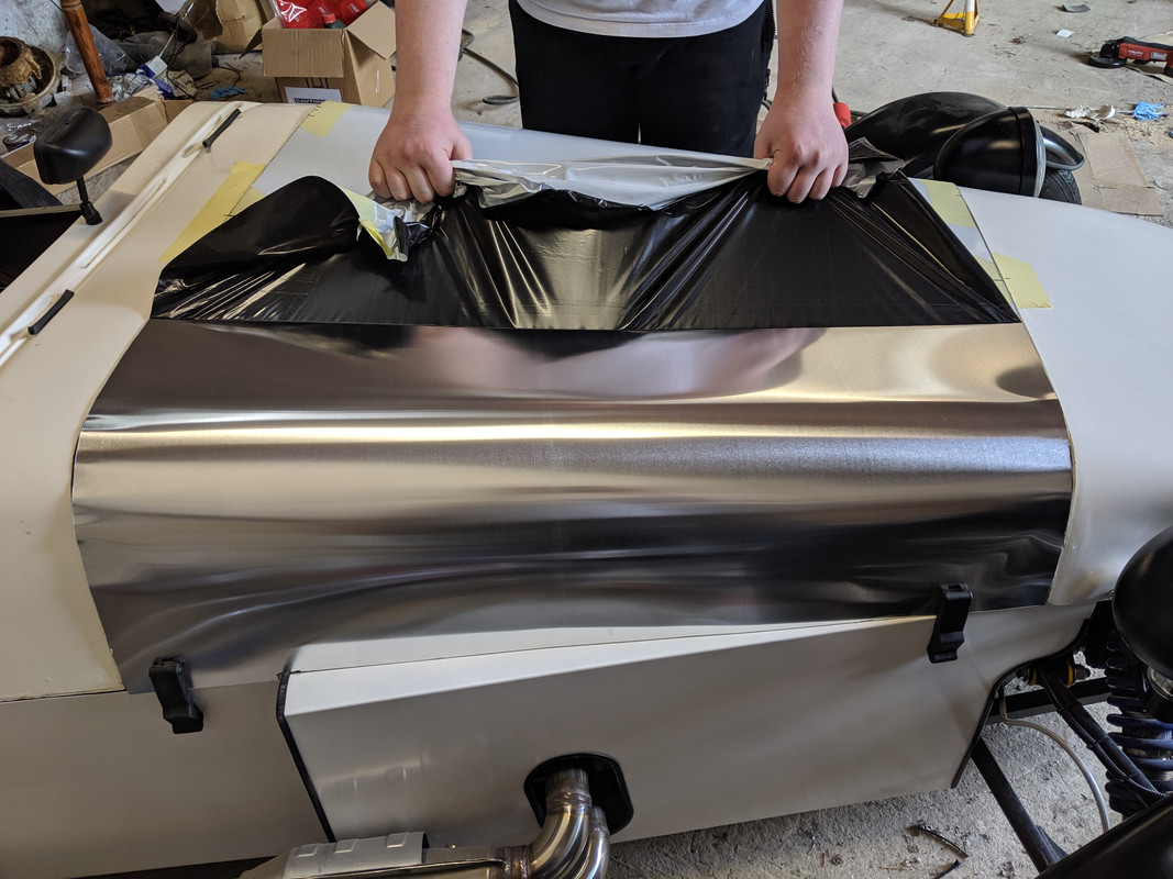
craigdiver - 10/8/19 at 03:22 PMJust moved house so this is the first opportunity to start painting my newly fabricated bonnet. Had to do some research as been ages since painting the body. Prepped bonnet by degreasing then roughing up with 800 grit, degreasing again then a thin coat of 1k etch primer. Went on ok.
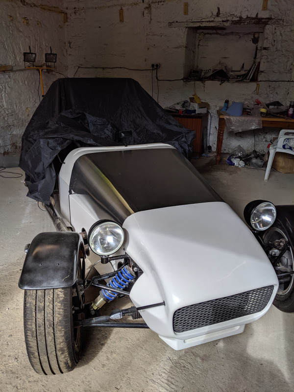
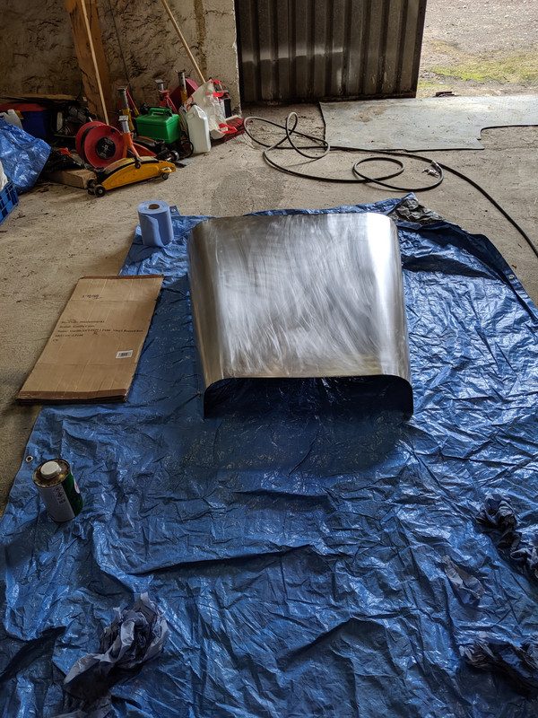
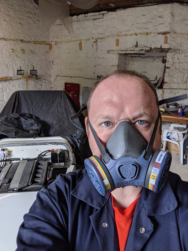
J666AYP - 10/8/19 at 03:33 PMBloody love that car!
starterman - 10/8/19 at 06:28 PMI might be wrong but I beleive that for IVA the edges of aluminium panels need to be rolled.
Cheers
Mike
craigdiver - 5/9/19 at 05:59 PMThank you.
quote:
Originally posted by J666AYP
Bloody love that car!
craigdiver - 5/9/19 at 06:03 PMThanks for the advice Mike, promise you it's much appreciated. Its not finished yet, I've got rubber profile to bond on which will bridge between the bonnet and nose cone / scuttle which will protect from sharp edges. Also got safe-edge profile to go on the rest.
quote:
Originally posted by starterman
I might be wrong but I beleive that for IVA the edges of aluminium panels need to be rolled.
Cheers
Mike
starterman - 9/9/19 at 06:25 PMquote:
Originally posted by J666AYP
Bloody love that car!
Gets my vote as well. Need more pictures though lol.
Cheers
Mike
craigdiver - 2/11/19 at 06:58 PMFinally got rubber seals bonded onto my bonnet and safe-edge on sides. Looking good (don't look too closely at the paint job!).
My son, Matthew, gave me a hand today to start the dashboard. Went very well. Fabricated aluminium pieces to cover tapered front section of transmission tunnel, centre dashboard panel and passenger side dashboard piece.
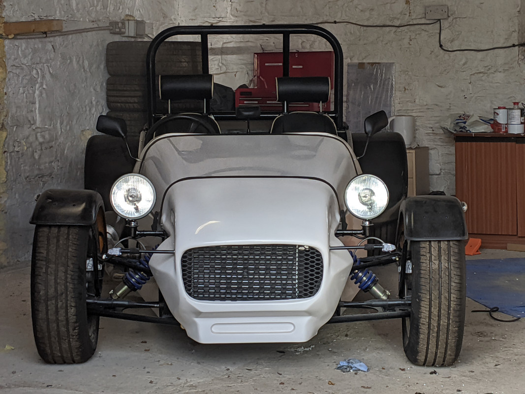
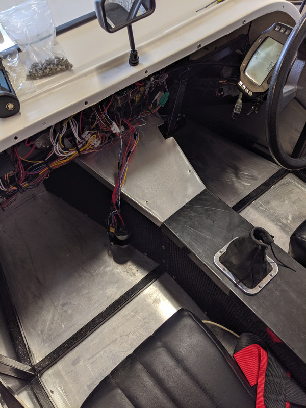
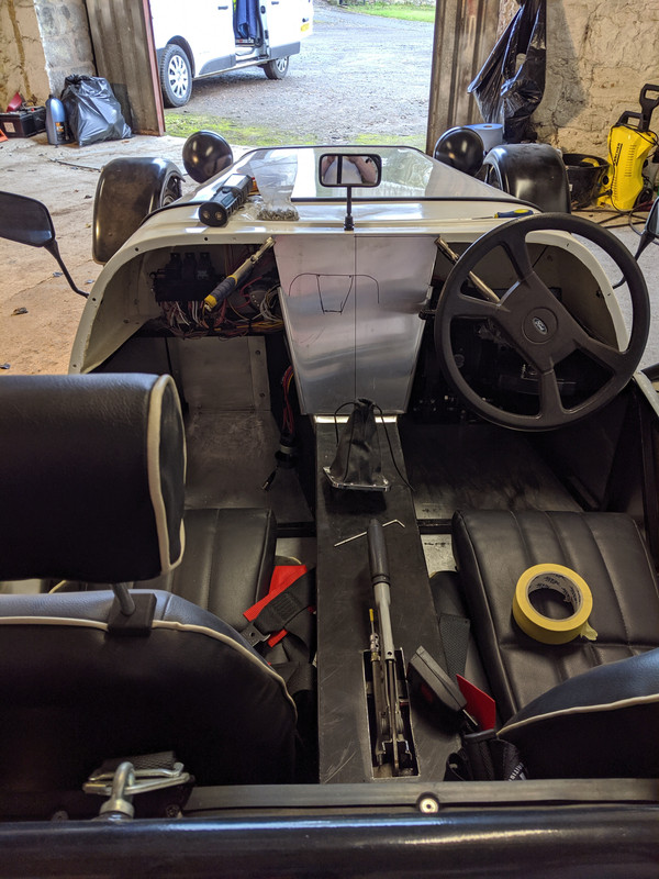
big_wasa - 2/11/19 at 08:17 PMI do like the nose on that.
craigdiver - 5/1/20 at 10:28 AMHi all, had problems with photos so have created a shared Google album that should stay put!
I do apologise for duplicate photos / lots of photos of what appears to be the same thing. The whole build has been a huge learning curve and I like to take photos so I know where things should be before dismantling!
Link to album.....
https://photos.app.goo.gl/inp5ryguhkBUpbpe6
Craig's Haynes Roadster build
big_wasa - 5/1/20 at 10:51 AMPhotobucket screwed a lot of people over
I’ve since deleted them all on there.
craigdiver - 5/1/20 at 11:14 AMquote:
Originally posted by big_wasa
Photobucket screwed a lot of people overI’ve since deleted them all on there.
That's who I started with them went to postimg who now appear to have gone the same way! I would have been happy for photobucket / postimg to use the links to advertise and gain revenue through that channel.
Just a shame anyone scrolling through our build diaries cannot see the associated photos.
craigdiver - 23/2/20 at 04:38 PMHad a busy weekend. Dashboard and interior. While dashboard was out fitted OBD socket to bulkhead. Also fabricated base for handbrake gaitor and got it undercoated. Found out my nearest IVA centre is Livingston. Will aim to book it in October time so if it needs retest I will have until March next year to fix.

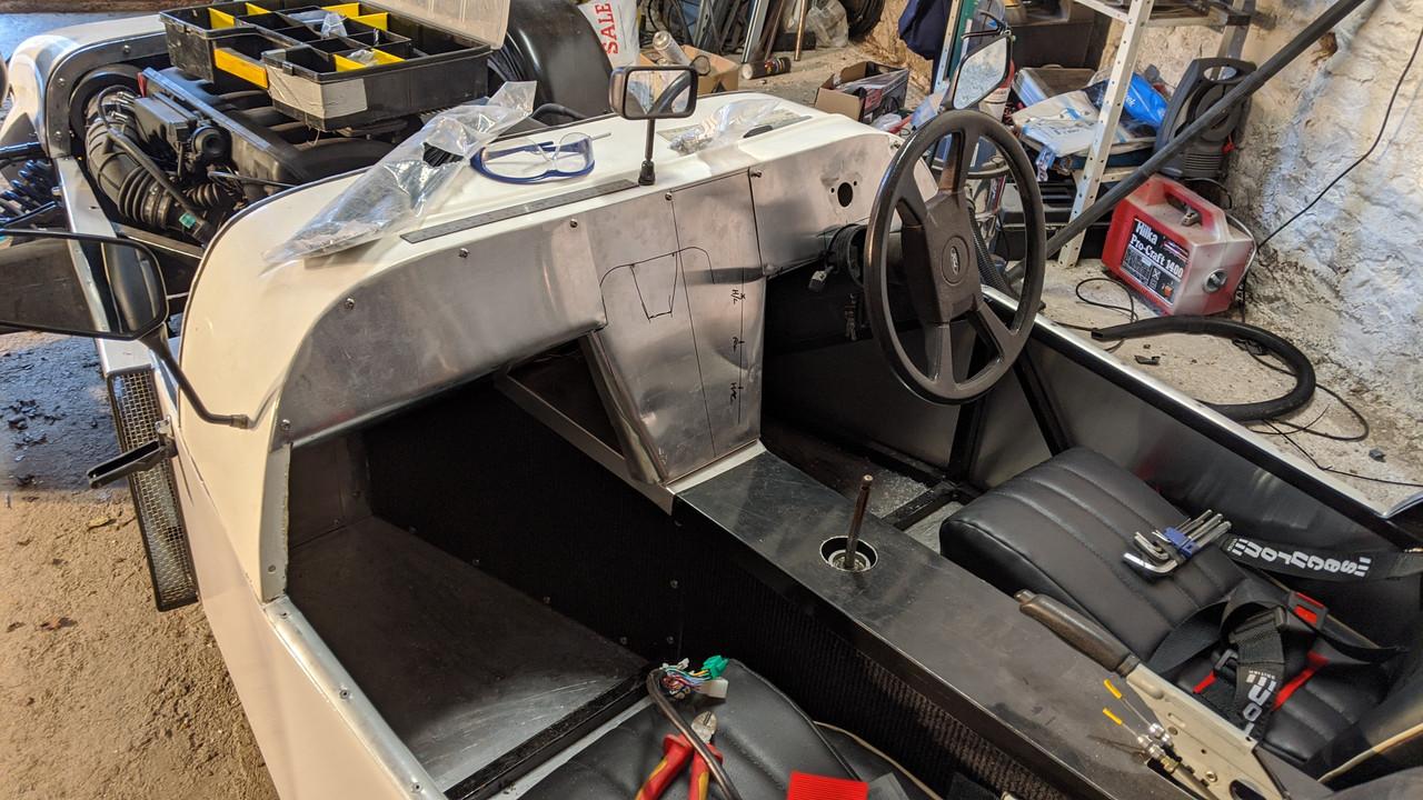

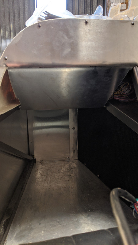
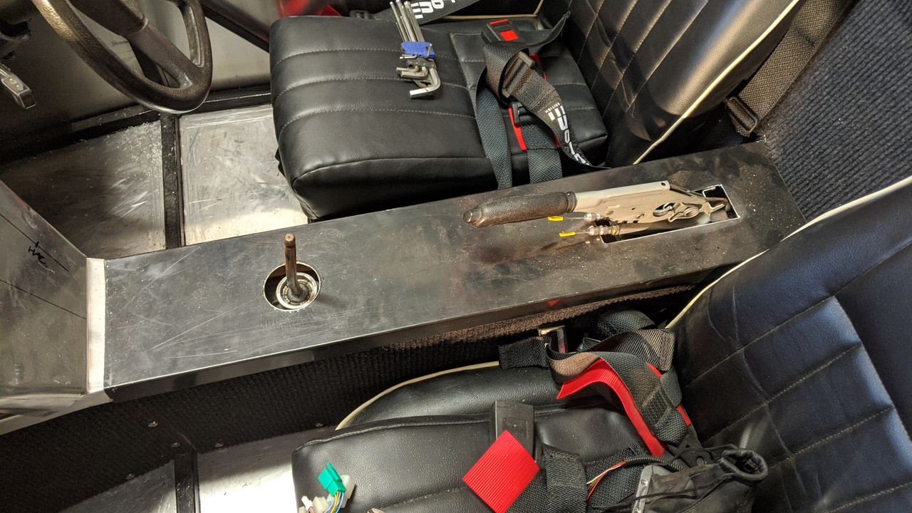
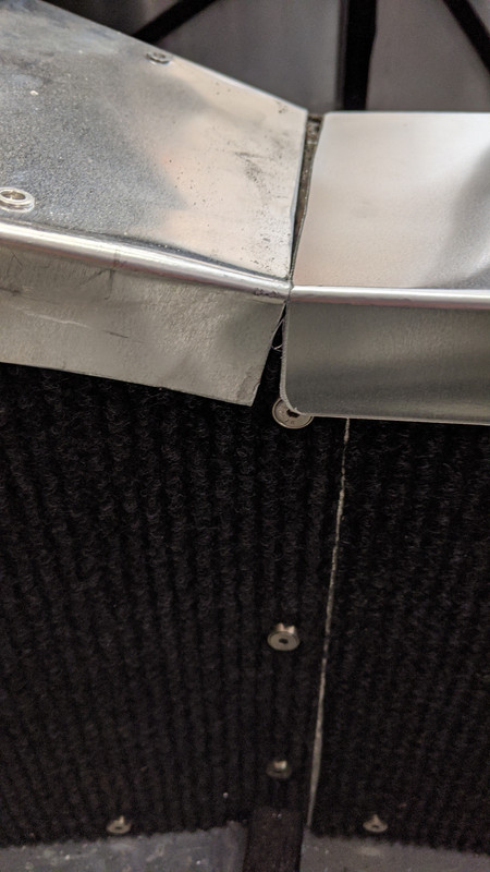


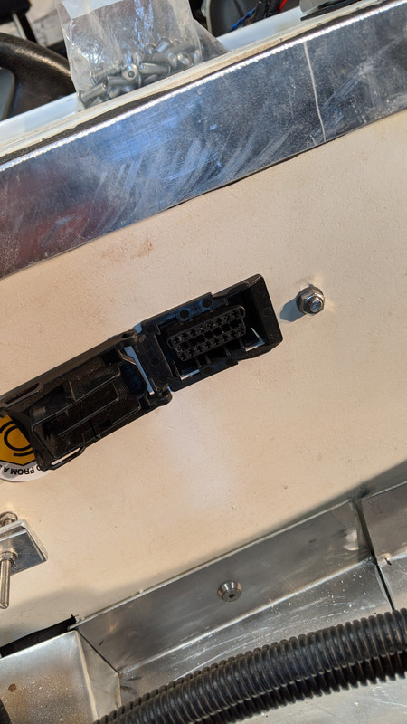
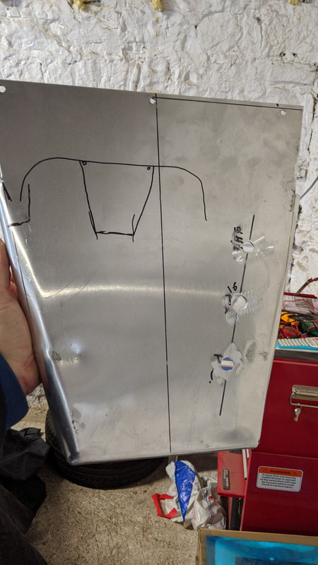
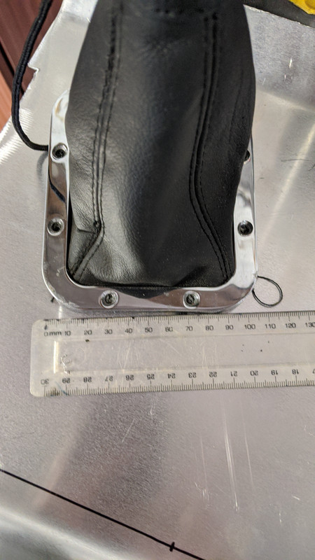
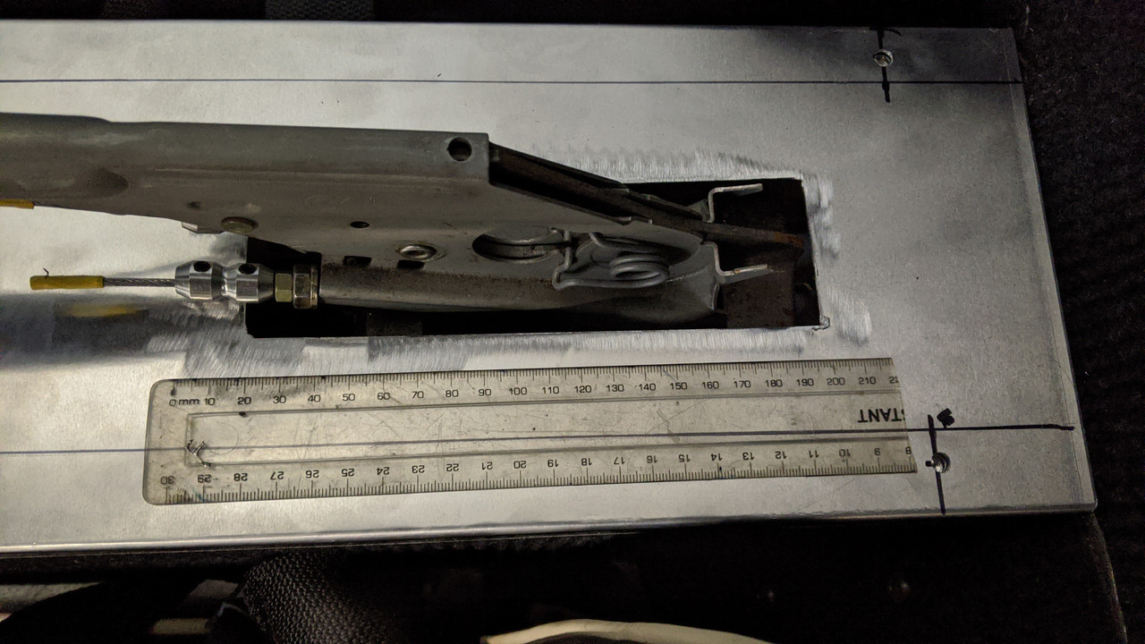
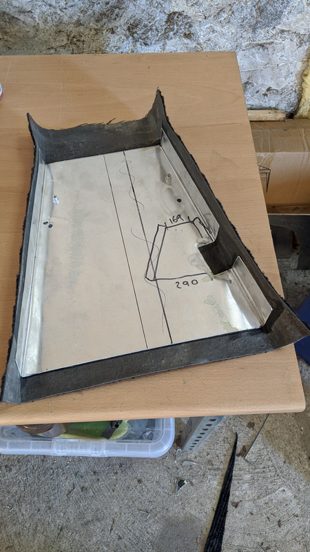
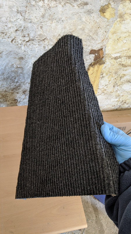
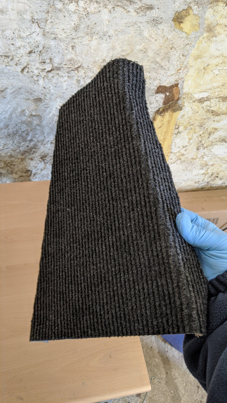
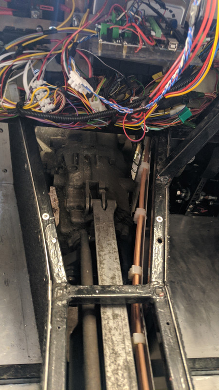
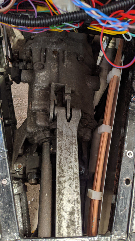
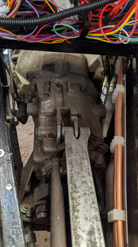


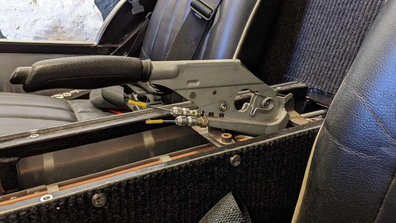
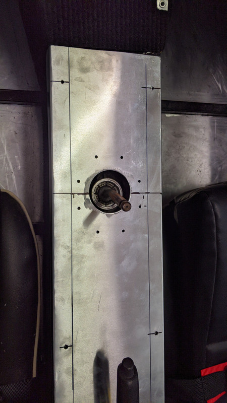
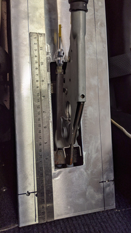
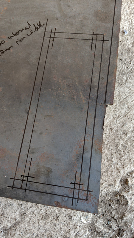
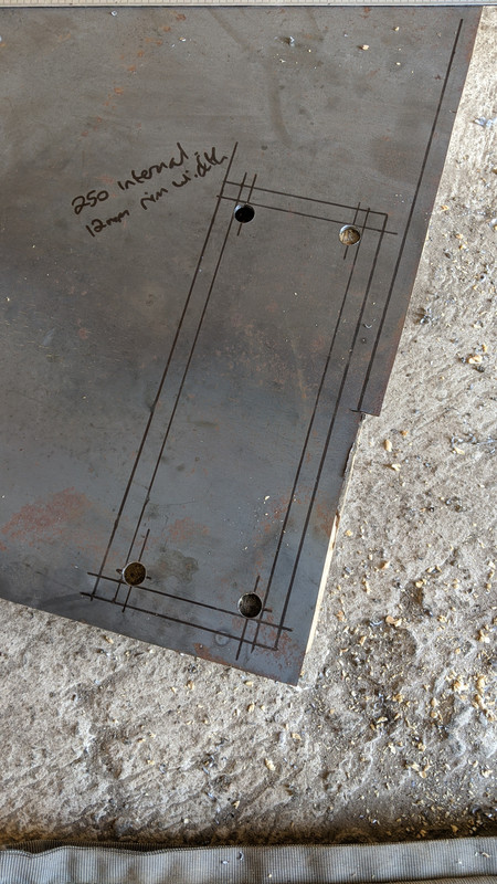

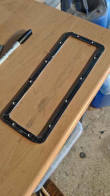


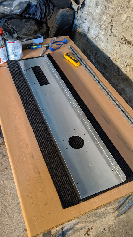
craigdiver - 2/3/20 at 05:39 PMSpent last couple of weekends working on dash panels and other interior stuff. Most of it came together this afternoon leaving me with what looks like a finished dashboard. Got a couple of bits of trim to add to the lower edges of the scuttle then that can be ticked off the list.
craigdiver - 20/3/20 at 08:22 PMThank you to my lovely Wife Karen for sewing up a custom handbrake gaitor for me.
craigdiver - 22/5/21 at 03:00 PMWell it has been a long but fun journey. I have decided to sell the car. New owner will decide whether to use as a track car or IVA for road use.
Advert on facebook marketplace (follow link below)
http://www.facebook.com/marketplace/item/817002339240136/