907
|
| posted on 2/8/07 at 05:31 PM |

|
|
Wiring LED Lights
Hi All,
I bought these LED rear light units from the SVC stand at Newark show and now wish to wire them up.
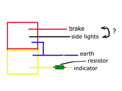
I'm a complete numpty when it comes to electrics but I've had a stab at what I think the way to wire them is. (see pic)
Because the white wire goes to both sides I assume that's the earth????
The red and the black I may have the wrong way round. Brake and rear light????
Yellow goes in the indicator side but it comes with a resistor (??) which I assume I should join to the yellow,
and the other end of the gold thingy should go to the flasher stalk???
Can the resistor be wired the wrong way? i.e. does it have an in and out?
Sorry if this is obvious to everyone else but it's all Greek to me. 
Many thanks
Paul G
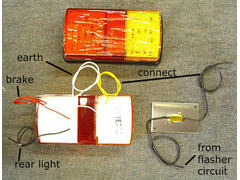 
Rescued attachment rear-light-wires-s.jpg
|
|
|
|
|
ironside
|
| posted on 2/8/07 at 05:39 PM |
|
|
Hi,
The resistor is to protect the LEDs, so I would've thought that it would have to go on the ground lead to protect all the sets of LEDs in the
cluster. Didn't it come with any instructions? 
It doesn't matter which way round you have the resistor though.
|
|
|
SeaBass
|
| posted on 2/8/07 at 05:53 PM |
|
|
Personally I thought the resistor was just to give enough load on the indicator circuit... this will make the indicators flash at the correct speed.
Most vehicle LED units have resistors built in to limit current.
Cheers
|
|
|
907
|
| posted on 2/8/07 at 05:58 PM |
|
|
I have assumed that it is to fool the flasher unit into thinking it's a 21w bulb???
No distructions, I mean instructions.
Hang on, I might have been right the first time. 
Paul G
|
|
|
ironside
|
| posted on 2/8/07 at 06:07 PM |
|
|
quote:
Originally posted by SeaBass
Personally I thought the resistor was just to give enough load on the indicator circuit... this will make the indicators flash at the correct speed.
Most vehicle LED units have resistors built in to limit current.
That makes sense resistor on flasher circuit only then.
|
|
|
David Jenkins
|
| posted on 2/8/07 at 06:09 PM |
|
|
I would suggest a conversation with SVC - Steve himself posts here, so should be able to give guidance.
|
|
|
owelly
|
| posted on 2/8/07 at 06:16 PM |
|
|
I would also say that all the LEDs will be 12v ones and the resistors are just for the indicator LEDs tomake them flash at the correct speed.
http://www.ppcmag.co.uk
|
|
|
BenB
|
| posted on 2/8/07 at 06:51 PM |
|
|
The resistor is VERY unlikely to be designed to be in the negative for both LEDs. If so the voltage to the LEDs would depend upon whether one or both
lights were on. IE if you had the brake light on the indicator would effect the brake light brightness which is possibly an MOT fail...
The resistor is much more likely to be to get the flasher unit wattage up to normal speed.
Check with SVC though. If you hook them on wrong (Eg if they're supposed to have series resistors) and blow them I doubt SVC will give you some
new ones...
...though not giving instructions sucks a bit!
|
|
|
907
|
| posted on 2/8/07 at 07:10 PM |
|
|
I phoned SVC at 1.45
Got an answer phone, left a message.
No answer, so I posted on here at 6.30.
Will try again tomorrow.
Thanks for the replies.
Paul G
They gave me the resistors when I bought the lights, so they are the right ones.
[Edited on 2/8/07 by 907]
|
|
|
Jon Ison
|
| posted on 2/8/07 at 07:18 PM |
|
|
you could do away with the resistor altogether and get a flasher suitable for leds, just takes the resistor out of the equation and one less thing to
keep dry or go wrong, that's the route I took ?
|
|
|
rusty
|
| posted on 2/8/07 at 07:22 PM |
|
|
I would think the resistor would go in parallel with the indicator, to, as said fool the flasher unit.
|
|
|
907
|
| posted on 2/8/07 at 08:33 PM |
|
|
quote:
Originally posted by Jon Ison
you could do away with the resistor altogether and get a flasher suitable for leds, just takes the resistor out of the equation and one less thing to
keep dry or go wrong, that's the route I took ?
Are all your indicators LED's Jon?
I have bulbs in the fronts and in the side repeaters.
Paul G
|
|
|
jkarran
|
| posted on 2/8/07 at 09:34 PM |
|
|
The white will be GND (0V) the three colours will be your +ve feeds to your three lights. The resistor (based on it's size) looks like an extra
load to keep mechanical flasher units in time, wire it between yellow and white.
jk
|
|
|
designer
|
| posted on 3/8/07 at 01:53 PM |
|
|
The resistor is to fit in the live circuit. You can't just wire LED's like bulbs.
|
|
|
907
|
| posted on 3/8/07 at 05:31 PM |
|
|
Thanks for all the replies.
I've phoned again and emailed but haven't had a reply yet.
So does this look right?
(blue = the white wire)
Cheers
Paul G
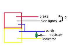 
Rescued attachment wire-diagram.jpg
|
|
|
rusty nuts
|
| posted on 3/8/07 at 06:22 PM |
|
|
Paul I think the resistor should go in the yellow feed to the L.E.D. , not one side to earth .
|
|
|
omega 24 v6
|
| posted on 3/8/07 at 06:40 PM |
|
|
As a guy who fits Leds to trucks on a regular basis the resistor always goes in the indicator line in parrallel as has been said already. It is to
create a dummy load for the flasher unit as said by others and yes your diagram looks fine.
[Edited on 3/8/07 by omega 24 v6]
If it looks wrong it probably is wrong.
|
|
|
907
|
| posted on 3/8/07 at 06:48 PM |
|
|
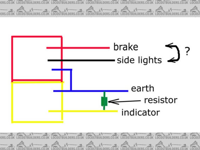
jk seems to think between feed & earth if I understand him correctly.
NOT like this ???? (see below)
I wish I had a brain
Paul G
Rescued attachment wire-diagram-2.jpg
|
|
|
omega 24 v6
|
| posted on 3/8/07 at 07:06 PM |
|
|
If you think about it and it needed to be in series they'd have to supply you with 3 resistors per light.
If it looks wrong it probably is wrong.
|
|
|
907
|
| posted on 3/8/07 at 07:21 PM |
|
|
Omega, I think your right.
If you join unequal wattage bulbs in series only the lower wattage one lights.
(er, I think)
I'll go for it.
Thanks a lot.
Paul G
|
|
|
907
|
| posted on 5/8/07 at 08:08 PM |
|
|
I received an email from Steve at SVC today.
He confirms that the resistor is wired between the power feed to the indicator (yellow) and earth (white).
He suggests that it is fitted at the dash end of the wire, not near the light itself.
Seems good advice.
Many thanks to ALL who contributed to this thread.
Cheers chaps
Paul G
|
|
|
tks
|
| posted on 5/8/07 at 08:14 PM |
|
|
quote:
Originally posted by 907
I received an email from Steve at SVC today.
He confirms that the resistor is wired between the power feed to the indicator (yellow) and earth (white).
He suggests that it is fitted at the dash end of the wire, not near the light itself.
Seems good advice.
Many thanks to ALL who contributed to this thread.
Cheers chaps
Paul G
he suggest that because in that way the "power" circuit is as close possible to the battery.
in series won't make anydifference because the resistance is that low that the leds will lit up normally (they have a higher resistance)
Tks
The above comments are always meant to be from the above persons perspective.
|
|
|


.jpg)