stuleah
|
| posted on 7/3/08 at 08:13 PM |

|
|
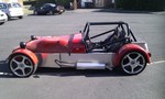
advice/opinions of chassis
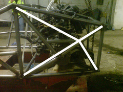
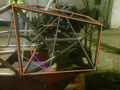
here is a picture of the rear left hand side of the car i am building, do you think that it would be strong enough like this or would you recommend
more bracing. i am not concerned with looks as it will be covered, but i dont want to go OTT and make it heavy. the diagonal bar lower right couldnt
be in line due to the drive shaft.

|
|
|
|
|
JC
|
| posted on 7/3/08 at 09:20 PM |
|
|
The only advice I would offer comes from one of Alan Staniforths books, High Speed Low Cost I think. He says never have a tube braced into the middle
of another -think of the load paths - all that will happen is that that tube will bend. You have 2 of these such joins as far as I can see. Have a
look at the rear of my car to see how I did it! Not that I am guaranteeing I have it right, it might just give you some other ideas! Hope this helps!
JC
|
|
|
stuleah
|
| posted on 7/3/08 at 09:28 PM |
|
|
i also read that somewhere and have been trying to stick to that rule hence the post, do you think if i carried on both tubes one to the top and the
other to the bottom it would be better?
|
|
|
JC
|
| posted on 7/3/08 at 09:59 PM |
|
|
You would then be transferring the 'bend' into the top and bottom rails, unless you could somehow get them to the corners. Try looking
for pictures of Terrapin single seaters, there is a forum out there somewhere, they will also give you ideas. I'll have a think overnight and
see if I can offer and constructive help!! Could you highlight where the driveshafts come through, I think I can see on the picture but it might
help!
|
|
|
Simon
|
| posted on 7/3/08 at 10:09 PM |
|
|
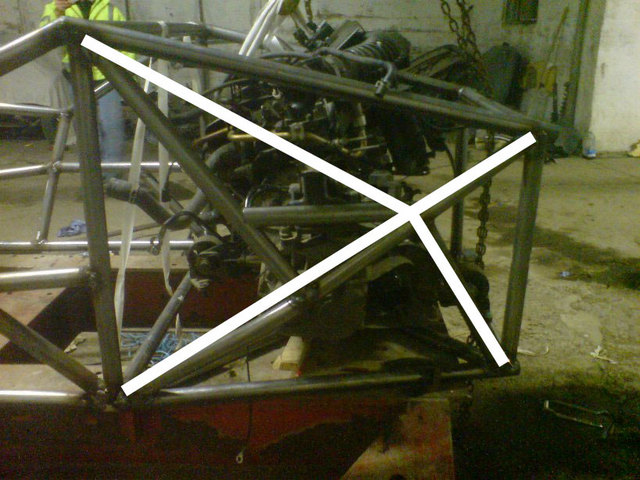
Triangulation is the key, so the quadroid(? ) we are looking at needs an X for strength. Rather than the way you have done it, which I suspect is so
mounting might be in the right place. ) we are looking at needs an X for strength. Rather than the way you have done it, which I suspect is so
mounting might be in the right place.
Get the triangulation right, then worry about mountings, they could double as reinforcement.
Imho of course
ATB
Simon
|
|
|
JC
|
| posted on 7/3/08 at 10:19 PM |
|
|
OK, I think I can help. I'll describe here then provide a picture tomorrow when I can get to photoshop! In place of the existing bracing, you
need to have a 'V' coming from the top left and top right, with its tip about where the join between the top and bottom right diagonals
is, although if possible, further to the left. Then have an inverted 'V' from bottom left/right, meeting in the same place so that
together, the tubes form a sort of distorted X. As I say, I'll try to illustrate tomorrow!!!! Hope this helps you, JC
|
|
|
stuleah
|
| posted on 7/3/08 at 10:48 PM |
|
|
cheers for your help simon and jc. just been doodling myself. do you think either of these would be better.


one point that cannot be seen on the picture is the angle from top right to bottom left is bent out slightly and then back in to go round the engine
|
|
|
indykid
|
| posted on 7/3/08 at 11:17 PM |
|
|
feeding loads into the middle of tubes is only terminal if the tube cannot withstand the bending moment.
nodes are ideal, but look where your wishbone brackets or engine mounts are on a 7. not 'ideal' but it works.
that looks like pretty hefty tube you're using there. where are your wishbone brackets going?
maybe that'll change things
tom
|
|
|
MikeR
|
| posted on 8/3/08 at 12:21 AM |
|
|
as previous said, move the centre of the X about a bit.
Eg, if you did it now the centre of hte X would be in the middle of hte open shape.
Move the centre of hte X to above the drive shaft. This should give clearance and mean nothing goes into the middle of a tube.
|
|
|
stuleah
|
| posted on 8/3/08 at 09:05 AM |
|
|
quote:
Originally posted by indykid
feeding loads into the middle of tubes is only terminal if the tube cannot withstand the bending moment.
nodes are ideal, but look where your wishbone brackets or engine mounts are on a 7. not 'ideal' but it works.
that looks like pretty hefty tube you're using there. where are your wishbone brackets going
the lower wishbone will be mounted just above the lower chassis rail where the bottom white line joins and at the back where the upright mounts, there
wont be an upper wishbone as it will be using a conventional layout. 9dont know what you call it). the tube is 38mm 2.5mm erw.
|
|
|
britishtrident
|
| posted on 8/3/08 at 09:41 AM |
|
|
quote:
Originally posted by indykid
feeding loads into the middle of tubes is only terminal if the tube cannot withstand the bending moment.
nodes are ideal, but look where your wishbone brackets or engine mounts are on a 7. not 'ideal' but it works.
that looks like pretty hefty tube you're using there. where are your wishbone brackets going?
maybe that'll change things
tom
Indeed yes --- in other words you have to draw a line somewhere to how much triangulation you can add.
Also agree we need to no more about where the suspension mounting points are.
[I] What use our work, Bennet, if we cannot care for those we love? .
― From BBC TV/Amazon's Ripper Street.
[/I]
|
|
|
JC
|
| posted on 8/3/08 at 10:20 AM |
|
|
How about something along these lines as a starter?
Rescued attachment smallrr2.jpg
|
|
|
stuleah
|
| posted on 8/3/08 at 06:22 PM |
|
|
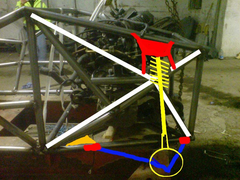
that looks good jc, i have added the one at the front mainly for piece of mind. here is a proper technical drawing(LOL) of what i have in mind for the
rear shock setup.
yellow is shock and hub , blue is wishbone, red are mounting points.
have a look at the rear of any car like mondeo, 406 etc and its a similar setup.
obviously i will have to brace the top mount somehow not quite got my head round that bit yet.

[Edited on 9/3/08 by stuleah]
|
|
|
indykid
|
| posted on 9/3/08 at 01:21 PM |
|
|
what does the horizontal tube do? is that engine mount attached to it?
if so, i guess it needs to be there.
what you've got to now looks well over engineered, bordering on fugly.
dependent on what actually needs to be there, i'd possibly consider cutting it all out and starting again. JC's last post looks
reasonable.
also, most of the forces on your lower wishbone will be trying to bend the lower tube inward and outward on braking/acceleration. most of the bump
load will be taken by the top mount. could you run the front leg of the wishbone further forward, more like a compression strut, to the node on the
rear bulkhead?
for the top mount, bring it wider rather than the triangular shape you have and brace it down onto the X structure.
tom
|
|
|
indykid
|
| posted on 9/3/08 at 01:37 PM |
|
|
here's a quick squiggle i did to try illustrate it.
orange bit's a gusset to a tube i assume runs under the engine bay btw
tom
[Edited on 9/3/08 by indykid]
Rescued attachment stuleah chassis.jpg
|
|
|
stuleah
|
| posted on 9/3/08 at 02:06 PM |
|
|
that looks easier and a lot neater, thanx guys. i think thats the way i will go.
what thickness steel should i use for the brace?
[Edited on 9/3/08 by stuleah]
|
|
|
britishtrident
|
| posted on 9/3/08 at 06:30 PM |
|
|
Think in 3 dimensions not 2.
Don't start adding members just because they make triangles is side elevation, consider the direction of the resultant forces at the suspension
mounting points.
|
|
|
britishtrident
|
| posted on 9/3/08 at 07:21 PM |
|
|
From the structural point of view this is what is required -- nb a few of the existing members are redundant --- but a pleasing appearance is more
important in this type of chassis.
Rescued attachment smallrraw.JPG
[I] What use our work, Bennet, if we cannot care for those we love? .
― From BBC TV/Amazon's Ripper Street.
[/I]
|
|
|
stuleah
|
| posted on 10/3/08 at 08:13 AM |
|
|
yeah i can see what you mean, this is a brilliant forum for learning on. thanks alot everyone.
|
|
|
stuleah
|
| posted on 10/3/08 at 08:44 AM |
|
|
ok, what do you think would be the best layout for the floor, bear in mind the seat will be positioned so you elbows are roughly where the V shape
is.


|
|
|
britishtrident
|
| posted on 10/3/08 at 05:18 PM |
|
|
If you weld a steel floor in will brace the structure, but use stiffeners welded on to the panel.
[I] What use our work, Bennet, if we cannot care for those we love? .
― From BBC TV/Amazon's Ripper Street.
[/I]
|
|
|
stuleah
|
| posted on 10/3/08 at 07:26 PM |
|
|
wouldnt that make it really heavy?
|
|
|
Benonymous
|
| posted on 11/3/08 at 11:58 AM |
|
|
Steel floor.
A steel floor would brace the chassis well, as would the tubular structure you suggest. However, with the tubes, you're going to have to put
some sort of sheeting on the floor to keep the mud,rain,snow,wind and debris out. Maybe an appropriate gauge steel floor would do the job nicely.
BTW. It looks like you're designing this thing in full scale. I'd anticipate scrapping at least two chassis in the process if this is
the method you are following. My suggestion would be to halt work on this chassis and draw up a design, followed by a balsa model as is often
suggested on this site.
To my way of thinking a home built design is an exercise in "reverse engineering". If you are using donor parts, they need to be factored
into the design at an early stage. This goes for wheels and tyres as well.
You may well have taken these steps but from your posts I'm thinking it's all being done "on the fly".
I'm not criticizing, I havn't even started my project yet., just food for thought.
|
|
|
stuleah
|
| posted on 11/3/08 at 06:43 PM |
|
|
hi
thanks for the advice, i have designed it on paper so i have a reasonably good idea of where i am going, but after joining the site and reading what
other people have done i thought i would get some opinions from people with experience before i make a pigs ear of it, so far what i have designed
hasnt been far from peoples ideas. the query on the floor is for 2 reasons 1 i am putting a complete floor under the chassis when its done using
sandwich type panel, so it would keep the weather out, and 2 i thought the overall weight and rigidity would be quite a bit different. i have read a
few posts on here where people have said they are for one way and others are for the other way so i think (no expert here) that its down to personal
preference.
by all means correct me if i am wrong, im here to learn.
|
|
|
Fred W B
|
| posted on 11/3/08 at 07:02 PM |
|
|
Ive been meaning to ask this question of the forum, and it has come up now so here goes.
IF a 3 mm ally floor was fitted with structural rivets, would you need any cross or diagonal bracing at the floor plane at all?
Cheers
Fred W B
You can do it quickly. You can do it cheap. You can do it right. Pick any two.
|
|
|