
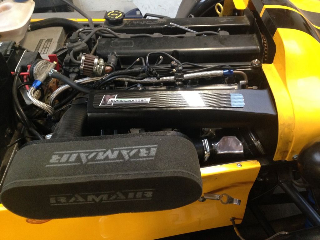
Blacktop supercharge project avon
Sierra - 23/12/14 at 09:25 PM
Good evening fellow kit car builders.
I currently have a tiger avon with a blacktop engine and m45 supercharger.
Over the next few months I want to take on an exciting project to upgrade a few bits including adding a larger m62 supercharger and front mount
intercooler.
Although I'm willing to give most things a go, I have never welded before and this is where I require some assistance.
It's a bit of a long shot but wanted to ask if there's anyone that does some private work, evening/weekends or can weld and is willing to
help me in this project. Or can recommend a garage that can do the work.
The areas where I will need help are
-cutting, extending and welding an inlet plenum that I bought to a different angle, roughly 45 degrees so it allows the charger to sit below.
-make and weld brackets to hold the charger in place
-inlet and outlet for charger, I currently have blank plates that cover the inlet and outlet.
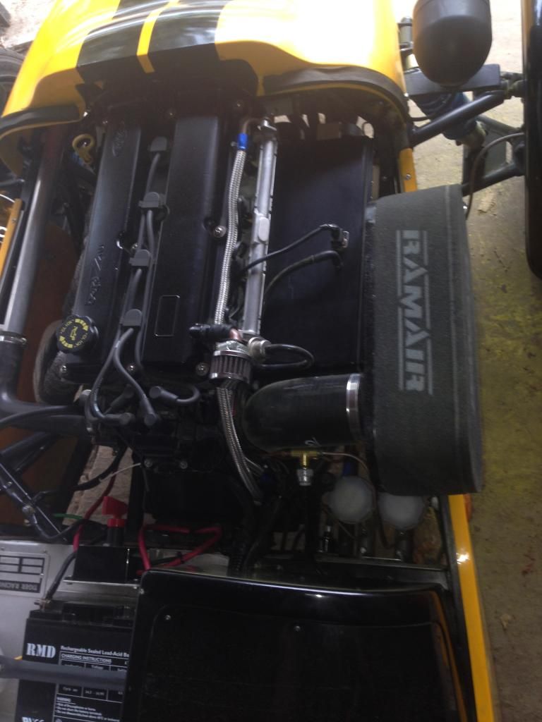
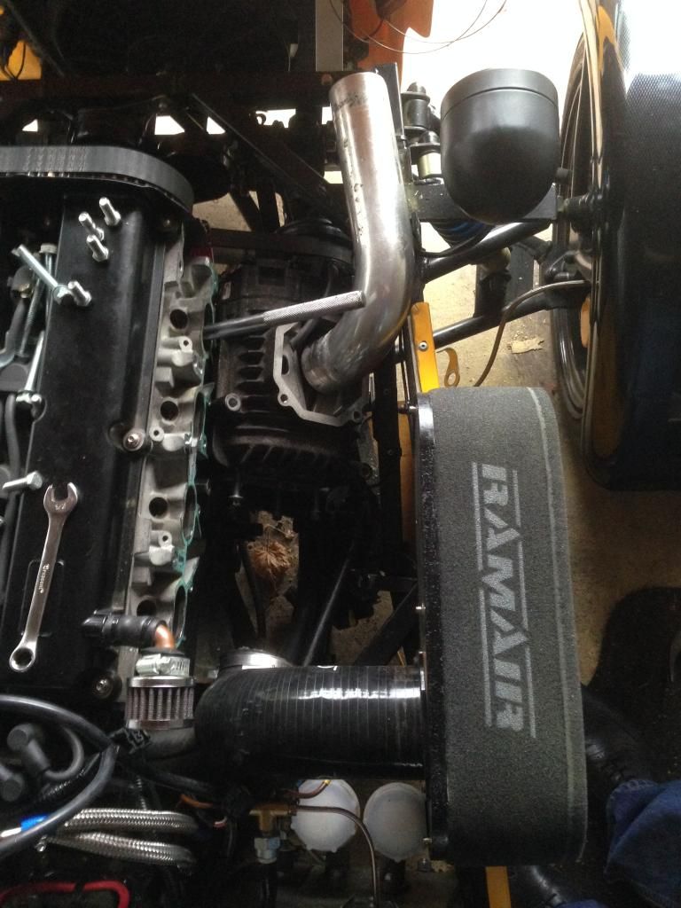
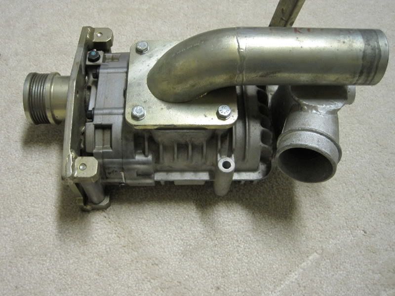
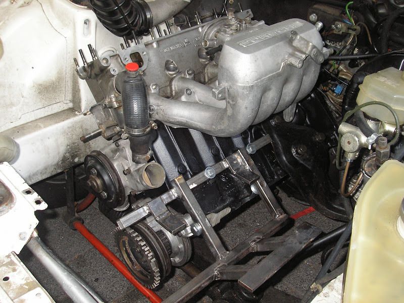
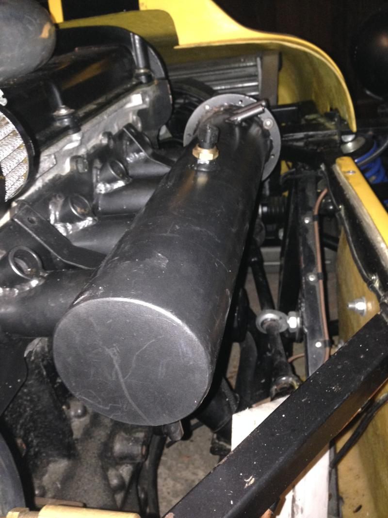
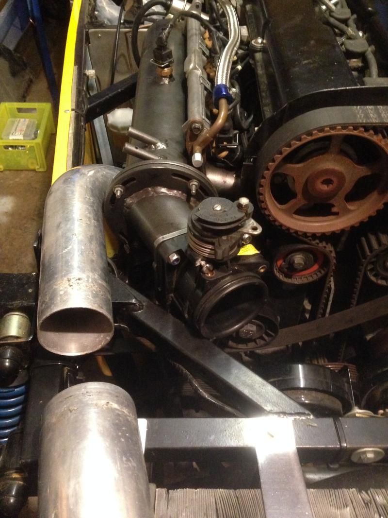
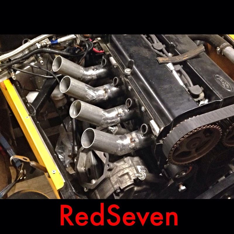
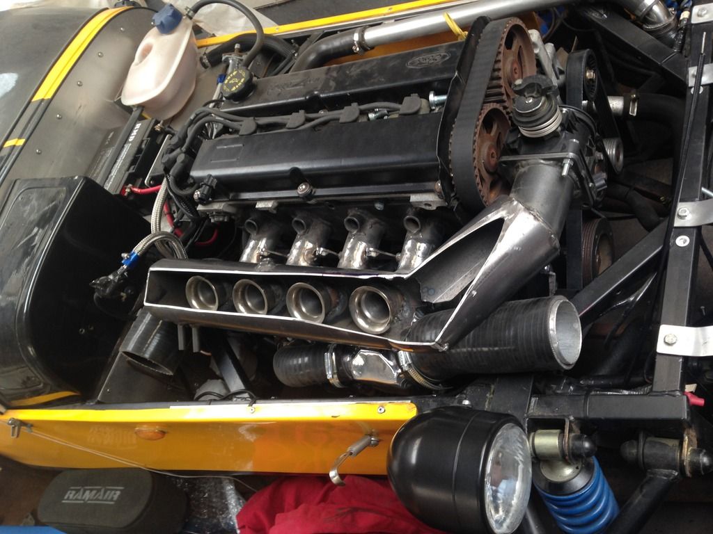
Old setup with m45 bolted straight to custom inlet.
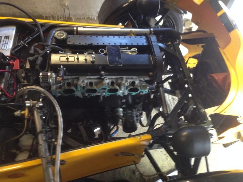
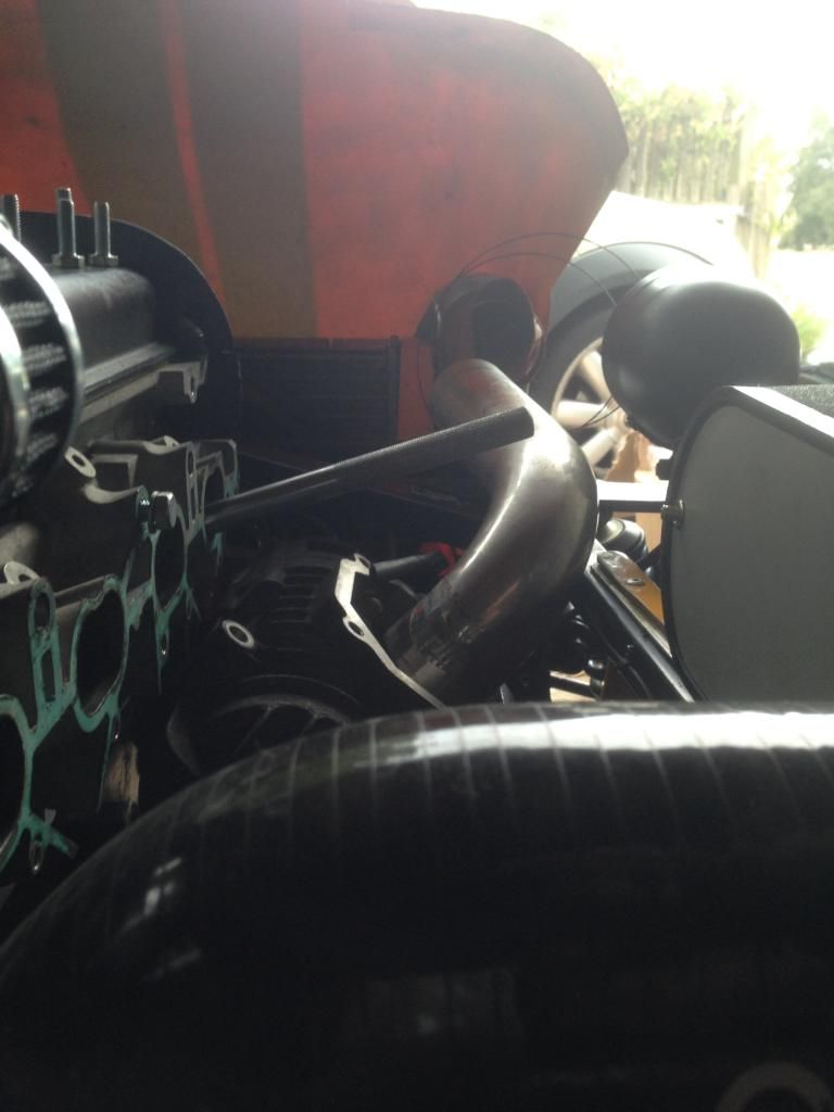
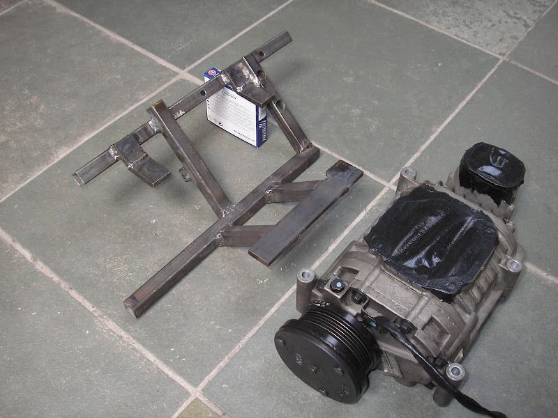
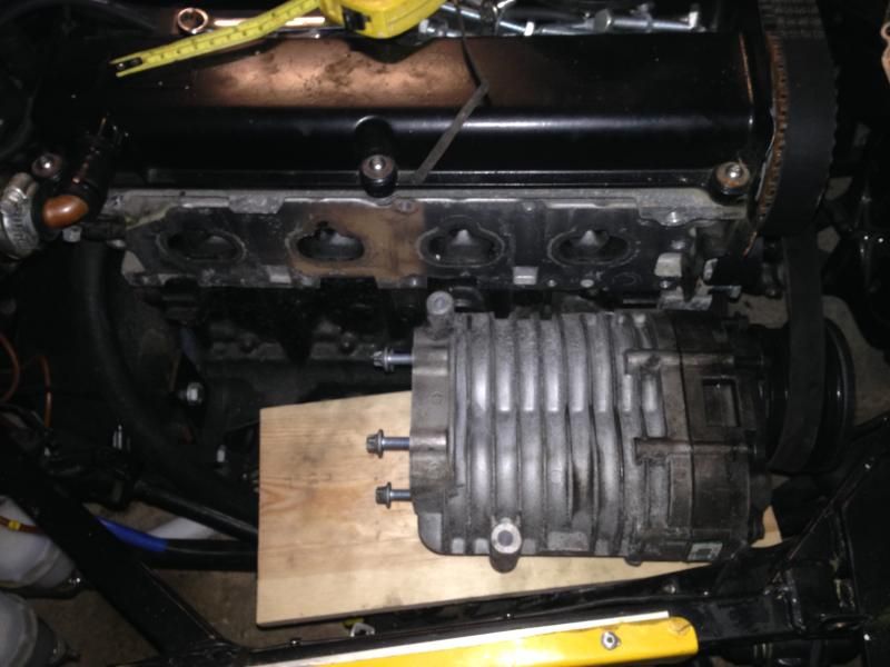
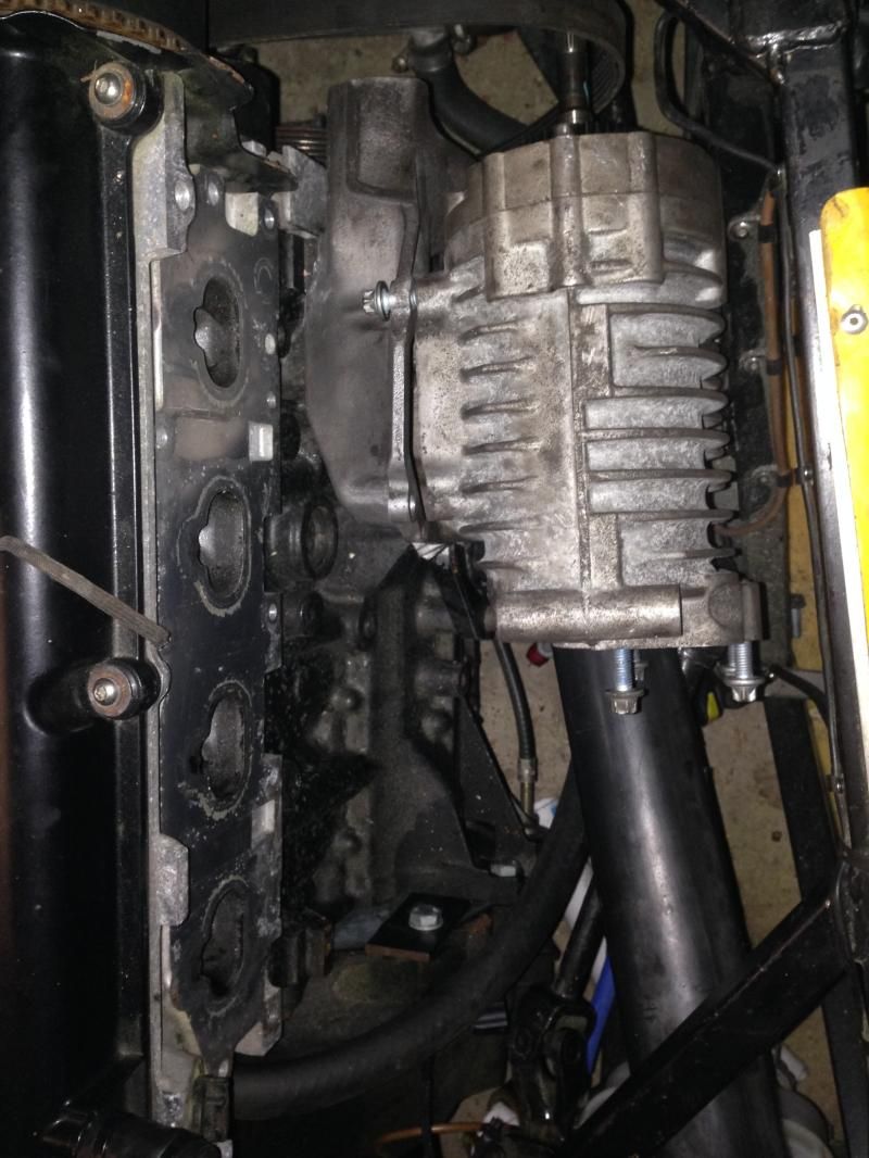
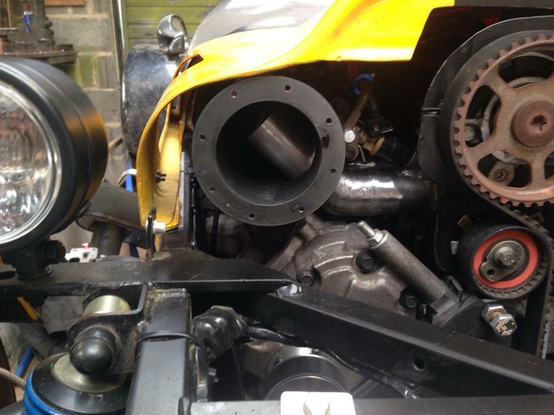
All stripped out
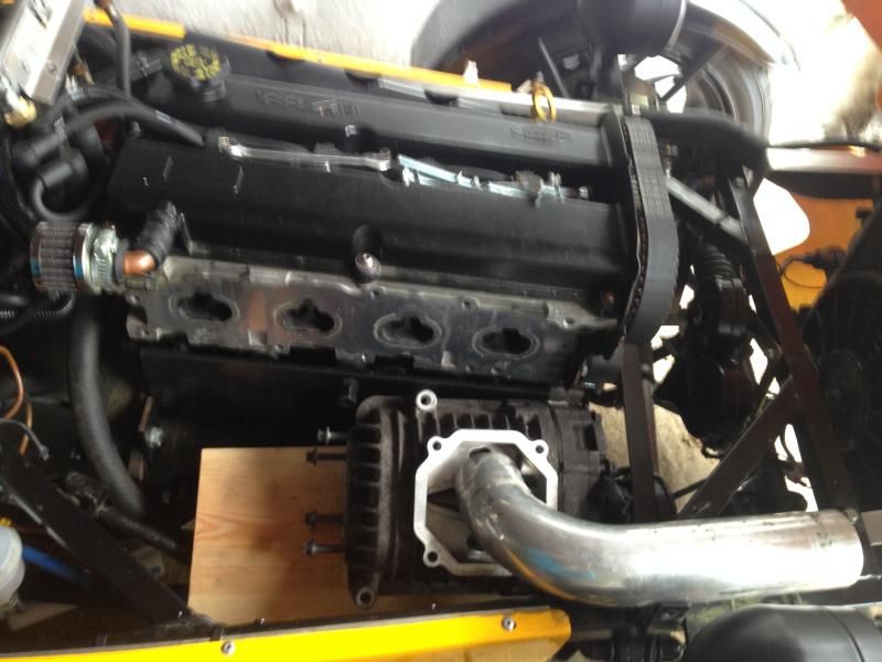
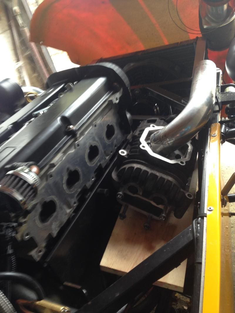
Where I want the m62 to sit (brackets need making)
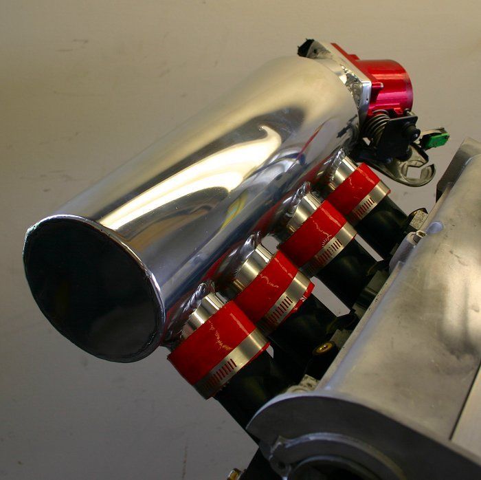
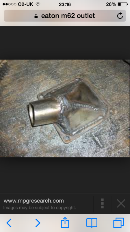
Examples of inlet/outlet that I need
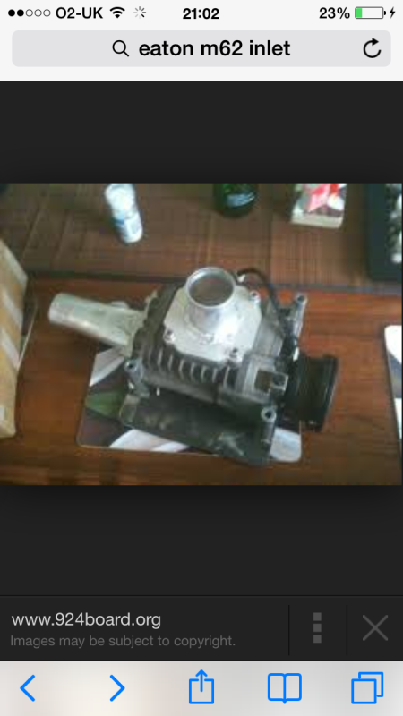
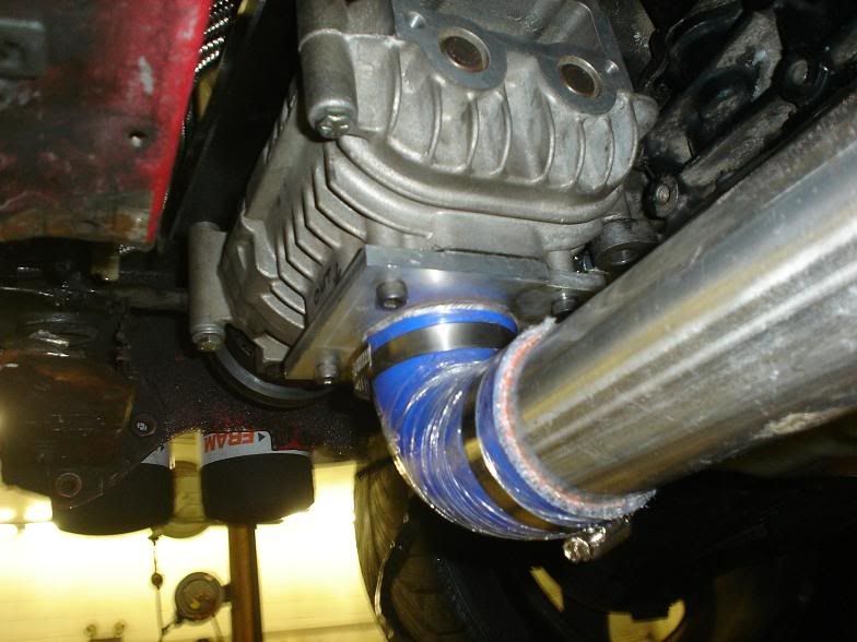
Example of a bracket made to hd the charger
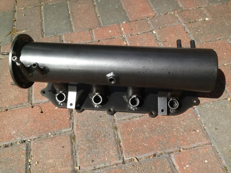
Inlet that I have purchased. (Needs cutting, 4 tubes extended and angled at roughly 45 degrees)
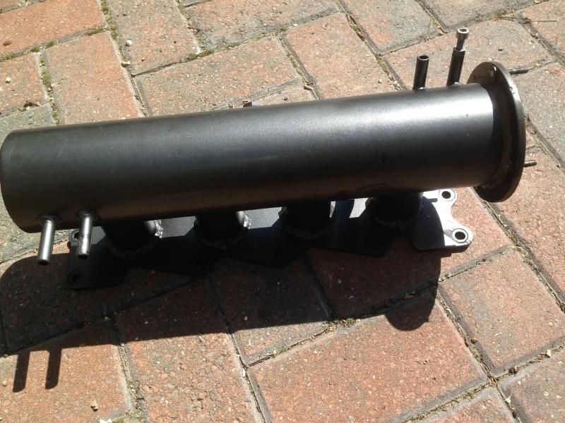
Rough idea of how the inlet should be angled
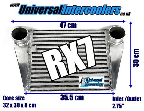
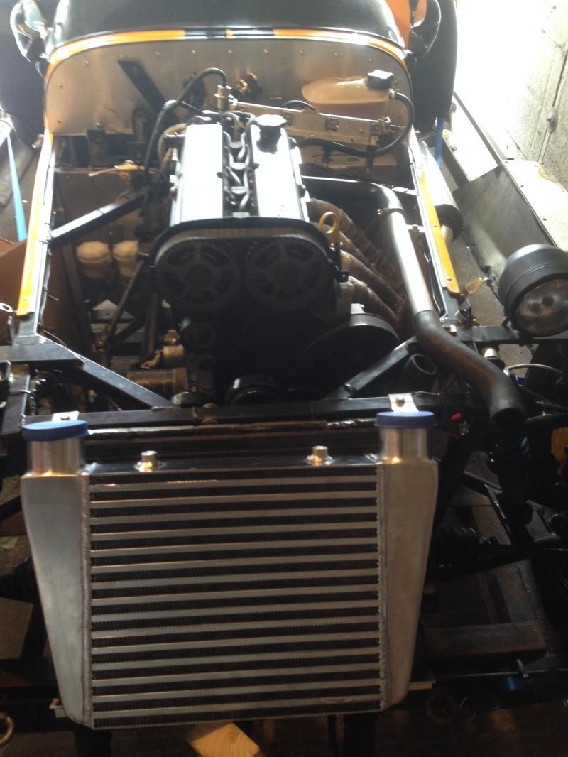
Intercooler that I will purchase
The only other question would be, do I fit the tb to the plenum after the charger and use a recirculating dump valve which is connected back to before
the charger
Or
Fit the tb before the charger like they do on the mx5's. Why do they have the inlet connected to the outlet like that though?
mark chandler - 23/12/14 at 10:20 PM
Putting a tube like that on the outlet of the charger will kill power, you need to make up a curved cone leading into the pipe towards the
intercooler, also the charger throws air towards the wide end of the V, so whoever manufactured the earlier photos that would have done better by
putting the tube towards the nose, the last one looks pretty good.
That aside if you fit up all the parts I can have a go at welding it together for you, I am about 1 hour away down the M4.
Regards Mark
[Edited on 23/12/14 by mark chandler]
Sierra - 23/12/14 at 11:18 PM
Many thanks for your advice and offer. I'll see if I can get bits together but I'm very new to this so might need help
So something like this would be better?
mark chandler - 23/12/14 at 11:50 PM
That's ugly but better than the flat plate/tube affairs, imagine how the air would flow so if you provided a nice curve from vertical to
horizontal then you are onto a winner so turn the air not bounce it off a 45 degree plate, use the side profile of the mandrel bend sculptured into
the 3" pipe.
Also remember the V is the exhaust port, not the square plate which is designed for mounting stuff easily.
Regards Mark
flak monkey - 24/12/14 at 09:15 PM
Shouldn't be that difficult to make a fabricated outlet for the blower. Maybe take half a day to do something to suit.
A log type inlet would be easy too.
Ref your question about the inlet connected to the outlet, see that black valve in the pipe? It's a BOV that prevents boost spikes when the
throttle plate is closed. You only need that if the throttle plates are AFTER the blower. If the throttle body is BEFORE the blower you don't
need one.
[Edited on 24/12/14 by flak monkey]
coozer - 24/12/14 at 09:19 PM
I have one of them intercooler with the little angle bracket cut off. Apart from that brand new never used with the pipes and clips.
Want it?
Sierra - 24/12/14 at 09:25 PM
I thought it was for that reason but got a bit confused as I could see the tb before the blower. Turns out they are running 2 tbs which is why they
have the dv. Although I was told that the vdw should go after the intercooler and before the tb which it seems isint the case with that one.
Are these things that you can fabricate then or know of someone that can?
quote:
Originally posted by flak monkey
Shouldn't be that difficult to make a fabricated outlet for the blower. Maybe take half a day to do something to suit.
A log type inlet would be easy too.
Ref your question about the inlet connected to the outlet, see that black valve in the pipe? It's a BOV that prevents boost spikes when the
throttle plate is closed. You only need that if the throttle plates are AFTER the blower. If the throttle body is BEFORE the blower you don't
need one.
[Edited on 24/12/14 by flak monkey]
flak monkey - 24/12/14 at 09:31 PM
If you can give me reasonable sketches of what you need I can look at the fabrication work for you if you need someone to do it for you.
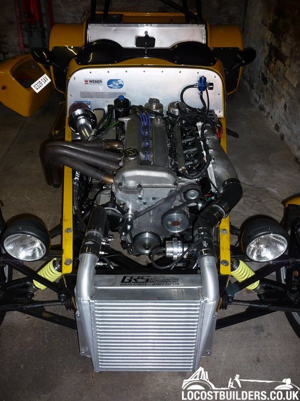
Good practice puts the BOV as close to the throttle plates as possible, so yes, normally after the intercooler. This was my set up.
Sierra - 24/12/14 at 09:39 PM
Wow that looks very nice, what setup is that and figures produced
flak monkey - 24/12/14 at 09:48 PM
2 litre Duratec - the build of it is in the stickies at the top of this section
Rotrex blower, 290bhp/240lbft @ 9psi - engine was built to take more. Simple change of pulley would allow peak boost of over 15psi.

[Edited on 24/12/14 by flak monkey]
jeffw - 24/12/14 at 09:51 PM
There was probable another 100-150BHP in Flak's engine. If you think mine is running 1.2 Bar or nigh on twice the boost as Flak's setup
using the same supercharger.
[Edited on 24/12/14 by jeffw]
Sierra - 24/12/14 at 10:10 PM
Very impressive setups, both of yours.
I would love a rotrex but really don't have the money for one. I'm trying to re build mine at the best price possible, plus it'll be a
bit of fun 
Sierra - 24/12/14 at 10:43 PM
I'll try and get some rough sketches together with measurements. I take it your DVD wasn't recirculating or is it just not visible in the
pic?
quote:
Originally posted by flak monkey
2 litre Duratec - the build of it is in the stickies at the top of this section
Rotrex blower, 290bhp/240lbft @ 9psi - engine was built to take more. Simple change of pulley would allow peak boost of over 15psi.
[Edited on 24/12/14 by flak monkey]
mark chandler - 24/12/14 at 10:50 PM
The eaton will not match those figures, it's a displacement charger so not as efficient, even with the same boost level it will be dragging HP
off the front pulley to spin it.
Saying that my DB7 has a M90, I like it 3.2 litre pushing 385bhp with over 300lb/ft above 2000rpm peaking to 370 lb/ft, not great figures per cc
but older technology running around 12 psi.
power run
Makes a great noise
http://youtu.be/v4OfO40D72w
[Edited on 24/12/14 by mark chandler]
Sierra - 24/12/14 at 11:04 PM
Oh yes definitely not expecting figures anywhere near that. Just want to upgrade so I'm not pushing the charger to its limits like I would be
with the m45 and this time have cooling with the intercooler.
Don't have a clue what the figures will be but that's part of the fun
jeffw - 25/12/14 at 08:16 AM
quote:
Originally posted by Sierra
I'll try and get some rough sketches together with measurements. I take it your DVD wasn't recirculating or is it just not visible in the
pic?
The DV is between the intercooler and the inlet (the shiny thing in front of the engine). Mine is off the plenum itself. You can do this with recirc
valves but it is probable better to have a 'To Air' DV as it will keep the inlet temps down a bit more than a recirc one.
mark chandler - 25/12/14 at 10:19 AM
You do not have a DV with an eaton, just the bypass valve as during low throttle openings it does not pressure the system.
Sierra - 2/1/15 at 10:48 PM
I had a spare but of time today so I test fitted the inlet that I bought a whole ago, just to see how it fits.
As you can see it is horizontal from the block so sits very low down. For me to be able to fit the charger underneath I need the plenum to sit much
higher up.
Do you guys think it would be best to cut the 4 ports straight just after the injector holes, then get someone to weld extended tubes at a 45 degree
angle. Or. Buy a new different inlet or have one made?
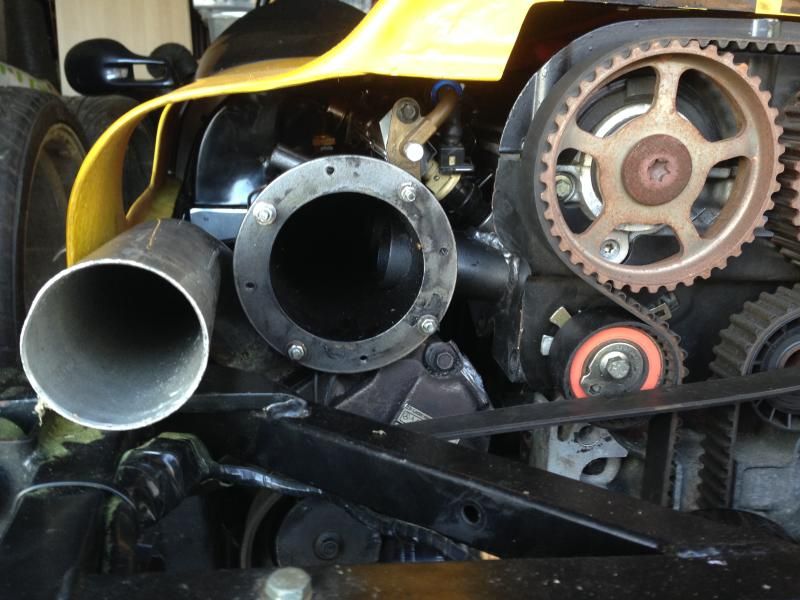
I also played with different positions for the charger again.
Outlet facing down
Charger side on
jwhatley - 2/1/15 at 11:16 PM
Good to see you are still fighting on with this project.
In my experience with these chargers as mentioned before, they are a pretty good heat pump, so keeping them and the charge air cool is a must.
I wouldn't use a BOV on this type of charger, dumping the boost to atmosphere sounds cool to some people, but the problem with doing this with
these chargers is the risk of belt slippage. I found that when using a BOV as a trial when the throttle was re opened and the BOV closed the boost
spike cause the belt to slip due to compressor stall. Not an issue on the likes of rotrex or vortec chargers as the puppy diameter is approx 25-30mm
larger.
I would suggest using a diverter/recirc valve and the TB's post charger. Have ithe diverter connected from the plenum back to the inlet of the
charger. I say this purely for cooling of the charger and the charge air. With the TB's closed or at partial throttle when driving you want to
keep the air flow running through the charger to cool it internally, using the intercooler also to cool the air and then port it back to the charger
inlet to be re used. If you have an efficient I/C this will work really well.
John
Sierra - 2/1/15 at 11:33 PM
Thanks for the info. I'm a bit confused when you say the diverter/ recirc at the plenum, do you mean after the tb.
I was going to fit the tb to the plenum so after charger and fit the recirc after the intercooler but before the tb. Recirc connected back to charger
inlet (between air filter and charger)
jwhatley - 3/1/15 at 06:48 AM
Hi,
Yes that's what I meant. I don't know why but I seemed to think you were going to use ITB's.
Sierra - 7/1/15 at 11:05 PM
Just a quick question guys.
What way does the crank pulley turn?
Just came to me if I will be turning the charger the correct way. The m62 needs to turn anti clockwise.
flak monkey - 8/1/15 at 07:12 AM
All engines, with a few exceptions of Hondas and early Citroens, all turn clockwise viewed on the front of the crank shaft (i.e. looking at the front
of the engine). Or CCW viewed from the flywheel end.
Sierra - 8/1/15 at 09:58 AM
Many thanks. Sorry I was having a bit of a blonde moment, when putting the rotors back in the casing I put them the wrong way making the charger ccw.
Now it's all correct it's cw like the engine
Sierra - 8/1/15 at 12:51 PM
Does anyone know what metal the griffin inlet plenum is made of? And where I could get inlet ports to extend the standard ones?
flak monkey - 8/1/15 at 12:54 PM
From the welds, looks like it might be steel - is it magnetic? Are the inlet tubes round?
Sierra - 8/1/15 at 03:18 PM
I don't have a magnet unfortunately but thinking how much it weighs it must be steel. Would they make it out of mild steel or stainless? Only
asking as when I buy the pipe work I can choose either of them.
Oh yes the ports are round, 45mm.
flak monkey - 8/1/15 at 06:31 PM
I expect it will be mild steel.
Sierra - 9/1/15 at 02:19 PM
Just a thought about post or pre charger tb placement. Which would you guys say is better?
On a post charger tb placement when you shut of the throttle the recirculating valve which is pre tb releases the extra pressure back to pre charger,
while at all times the charger is spinning getting fresh air from the air filter.
Now with pre charger tb placement when you shut of the throttle the bypass valve will again release any extra pressure from post blower to pre blower
only this time the charger continues to spin but without any air from outside. Question is wouldn't the charger now produce a lot of heat?
rdodger - 9/1/15 at 04:58 PM
If you use a pre charger TB then it will run quieter and cooler. If you then have long pipe runs/ intercooler to the inlet you may have trouble with
lag, unthrottled air, idle droop, stalling etc as there is quite a large volume there.
If you put the TB on the inlet you will probably want to run a dump valve along with the bypass. Back pressure when the throttle snaps shut can damage
the charger. Ask me how I know! The supercharger will also be very loud on part throttle.
A lot of MX5 M45 supercharged owners run dual TB's These are linked together. The idea is to get good throttle response and idle. The draw back
is lots of heat at part throttle plus balancing the 2 is problematic.
I would use the TB on the inlet and have the inlet to the supercharger going through a couple of easy bends and put the filter in a box. That should
help with the noise. Short inlet to the charger with a cone filter works like a megaphone. At WOT both set ups are equally loud.
The JRSC kits for MX5's put the TB on the charger and a dummy TB containing the idle air valve on the inlet. They just used a link pipe not an
I/C and these worked ok. Add an intercooler and it starts to become a problem again.
Sierra - 9/1/15 at 05:12 PM
Can I ask why the post charger tb setup creates more heat then the pre charger tb setup?
My supercharger m62 does not have a bypass so I would simply be running 1 recirculating valve. Recirculating from pre tb post intercooler to pre
charger post air filter.
I believe the recirculating valves are closed until you lift off throttle then recirculates back to pre charger.
Is it worth using a recirc valve instead of a blow of valve
[Edited on 9/1/15 by Sierra]
bi22le - 9/1/15 at 05:23 PM
Can i ask another question to the pros?
Do ITB make things any easier or different?
I am assuming that the currently discussed MX5 had direct injection and seperate singularTB.
rdodger - 9/1/15 at 06:14 PM
It's generally thought that ITB's offer little benefit and certainly not money well spent with FI,
With FI you are ramming as much air in as you require anyway. If you fit a charger that supplies the right amount of air to the engine to produce the
required amount of boost..........
If you were using a Rotrex or other centrifugal charger then it might be better as I would imagine throttle response would be better. Marginal though
I bet.
With the MX5 the injectors stay in the inlet manifold and people generally use the standard TB. I did use a larger (70mm)TB but again the increases
are minimal.
bi22le - 9/1/15 at 06:50 PM
Thanks for the insight.
I am planning on doing my 4age at some point with an m62. Bigger charger spun slower.
I was hoping to just keep the ITBs, no other TB added, and just have a recirc valve fitted between the plenum and the SC inlet. Boost control via a
set sping in the recirc.
rdodger - 9/1/15 at 07:03 PM
quote:
Originally posted by bi22le
Thanks for the insight.
I am planning on doing my 4age at some point with an m62. Bigger charger spun slower.
I was hoping to just keep the ITBs, no other TB added, and just have a recirc valve fitted between the plenum and the SC inlet. Boost control via a
set sping in the recirc.
No reason not to use ITB's if you have them, though I might sell them to fund the sc?
With a supercharger boost is controlled by the pulley ratio. An M62 would normally be run at a ratio of 1:2 crank:SC that should keep it within
it's rev range for efficiency and life. The recirc valve is there to dump boost when you close the throttle or cruising it stays open to bypass
the charger.
To give you an idea. On my 1.8 mx5 running an intercooled MP62 on 1:2 ratio I got 240 bhp 220 ftlb which was about as far as I wanted to take the
standard engine. That was about 10psi.
Sierra - 9/1/15 at 07:10 PM
The m62 do not have a bypass like the m45, well mine doesn't anyway.
What reason does the bypass stay open and bypass the charger on low throttle, will it cause issues if it just went through the charger all the time?
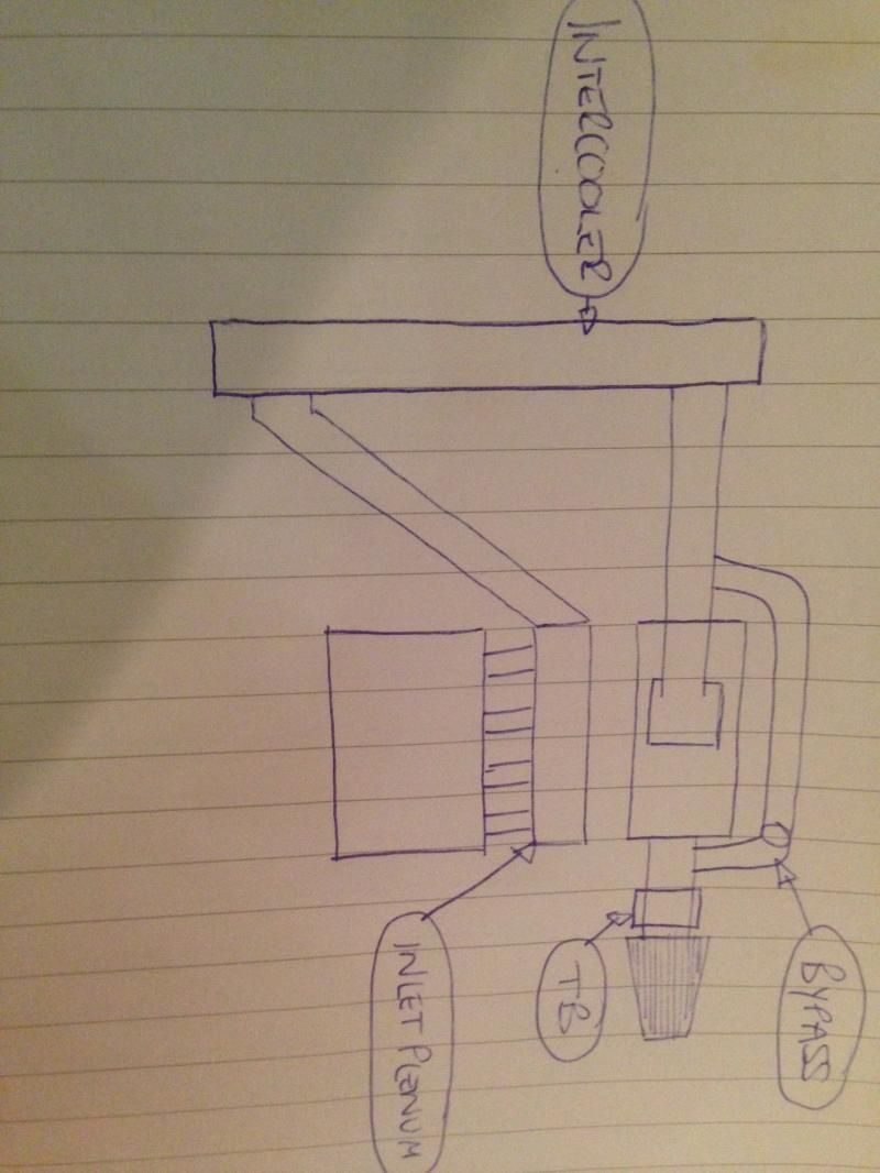
Sierra - 9/1/15 at 07:47 PM
Here's a rough sketch of my setup.
As you can see there's no bypass valve but there is a recirc after the cooler

rdodger - 9/1/15 at 08:09 PM
That's fine.
That will work in a similar way. When manifold pressure is in vacuum the recirc valve will be dumping boost.
Sierra - 9/1/15 at 08:14 PM
Thanks. Is there any advantage of recirculating the air back to the charger as oppose to just dumping it atmospheric.
rdodger - 9/1/15 at 08:22 PM
Depends really on whether you are using MAF or MAP and if you like the chavtastic Psssssst.
If MAF then the ECU can get confused if you dump to atmosphere.
bi22le - 9/1/15 at 10:23 PM
Thats the same setup as i was going to do. I under stand that max boost is achieved at max RPM.
I was unsure how the boost will change when the CC is so reduced compared to what the M62 is used to. I like the idea of running the SC as much as
possible then bleeding off the rest using a recirc with a dictated pressure spring. These types of recirc are freely available.
I am hoping to to govern and gaurentee my max boost this way and get more of a turbo boost curve.
As the eaton chargers are basically pumps this will also hopefully do other things. It may reduce inlet temps and reduce parasitic power losses.
I dont know if this Is going to work. I dont anything with this set up and just dreamt it up, but i like it!!
rdodger - 9/1/15 at 10:41 PM
My experience with the MP62 was it gave about 9psi as soon as it came in then climbed to about 10psi at max rpm.
Unlike a turbo the boost stays pretty constant. The faster the SC pumps the air, the more air the engine is using due to the crank driving the SC on a
constant ratio.
The idea is to match the size of the SC to the engine and run a pulley ratio to keep the SC in it's most efficient window. Bleeding boost is a
waste.
This of course is different with a centrifugal SC.
Sierra - 9/1/15 at 11:43 PM
I've currently got a couple of pulleys for the charger, one is 60mm and the other 62mm. So as the crank pulley is 130mm that will give me a
ration of 2.16 on the 60mm and 2.09 on the 62mm. Does anyone know how to work out what level of boost this would produce?
I've been doing some research on the m62 chargers and apparently
Safe continuous rpm is 14,000rpm
14,500rpm ported
Safe Max rpm limit 15,500rpm
Look at gearing car max rpm (7,000rpm) to max charger rpm 15,500rpm
jeffw - 10/1/15 at 07:37 AM
quote:
Originally posted by rdodger
It's generally thought that ITB's offer little benefit and certainly not money well spent with FI,
With FI you are ramming as much air in as you require anyway. If you fit a charger that supplies the right amount of air to the engine to produce the
required amount of boost..........
If you were using a Rotrex or other centrifugal charger then it might be better as I would imagine throttle response would be better. Marginal though
I bet.
With the MX5 the injectors stay in the inlet manifold and people generally use the standard TB. I did use a larger (70mm)TB but again the increases
are minimal.
The case for ITBs over single TB is the same regardless of NA or FI. ITBs give a much better throttle response, it has been described as the
difference between being directly connected to the engine (ITBs) or being connected via a bowl of porridge (TB). The ultimate power will be the same
(assuming a TB of sensible proportions) but the finesse on part throttle or throttle pickup is much better with ITB.
jeffw - 10/1/15 at 07:43 AM
quote:
Originally posted by Sierra
I've currently got a couple of pulleys for the charger, one is 60mm and the other 62mm. So as the crank pulley is 130mm that will give me a
ration of 2.16 on the 60mm and 2.09 on the 62mm. Does anyone know how to work out what level of boost this would produce?
I've been doing some research on the m62 chargers and apparently
Safe continuous rpm is 14,000rpm
14,500rpm ported
Safe Max rpm limit 15,500rpm
Look at gearing car max rpm (7,000rpm) to max charger rpm 15,500rpm
(7K x 130)/60 = 15167
(7K x 130)/62 = 14677
To get 15500 rpm at 7000 you need a pulley of 58.7mm
Are your diameter measurements at the bottom of the V grooves or the top?
Sierra - 10/1/15 at 09:35 AM
The measurements are at the top of the v groove.
I'm not sure if going any smaller will be pushing it and create belt slip
mark chandler - 10/1/15 at 09:37 AM
The level of boost will depend upon your engines ability to breath, a poor breathing engine will result in more boost and heat as you are effectively
feeding air into a funnel.
A good analogy is pumping air into your push bikes tyre, pump like mad and it's hard work and the Schrader valve gets hot so just go for a
maximum speed matched pulley and pay attention to the head, inlet tract and exhaust.
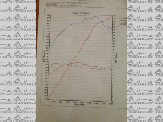
You will also find that a rootes charger ability to push air goes off as the rotors spin at high speed so there is no point overspeeding, if you look
at the chart I posted earlier for my DB7 you can see the boost dropping off which clearly demonstrates this as the engine is struggling to breath at
high revs so the boost should increase but the charger has lost efficiency, at low revs the boost is low as the engine can easily pass the air.
I,ll be pulling the head off this car maybe this year, port matching and cleaning up the head, this will result in less boost shown but more power as
the power dragged off the nose of the crank reduces along with inlet charge heat so a win win.
Regards Mark
bi22le - 10/1/15 at 10:12 AM
quote:
Originally posted by rdodger
My experience with the MP62 was it gave about 9psi as soon as it came in then climbed to about 10psi at max rpm.
Unlike a turbo the boost stays pretty constant. The faster the SC pumps the air, the more air the engine is using due to the crank driving the SC on a
constant ratio.
The idea is to match the size of the SC to the engine and run a pulley ratio to keep the SC in it's most efficient window. Bleeding boost is a
waste.
This of course is different with a centrifugal SC.
I agree with almost all of this as i am using a larger SC. The M62 is used on engines twice my size so expect it to be able to over boost my car
beyond the efficency of the SC which is why it needs to be controlled. I will try and get the ratio of pulley correct but want a fail safe.
Bleeding boost on the face of it seems silly but let's think about the pump idea. If a pump spins faster than the work required the waste will
allow the pump to spin with relative ease as long as the recirc can flow the volume of air that needs to be wasted.
Another way of looking at it is the torque on the SC pulley would be greatly reduced if you just removed the outlet completely, it would greatly
increase if you just blocked it off 100%.
This meeting in the middle could reduce parasitic losses once the prescribed boost has been achieved. In fact i expect this excess of air to help cool
the charger because the air is being passed through the charger and bleed straight off requiring little effort. I also wonder if the wasted and now
cooled (post IC) decompressed air released into a chamber in front of the charger would reduce inlet temp to the charger, using the refrigeration
principle.
Sierra - 10/1/15 at 10:41 AM
But is the air being recirculated from post intercooler really going to be much cooler than the air coming in pre blower?
Cause if it's not then you'll just be recirculating warm air which wouldn't help the charger
[Edited on 10/1/15 by Sierra]
jeffw - 10/1/15 at 11:21 AM
Recirculating is a great way to raise the inlet temp. I originally did this and found if I dumped to atmosphere it dropped average inlet temp by 10
deg C.
I had it as a recirc to cut out the annoying noise but given the temp issue I'm prepared to live with the Max Power wooosh.
rdodger - 10/1/15 at 11:27 AM
I would say you really don't want to over spin the charger.
It leads to a large increase in inlet temps and much reduces the life of the charger.
130-62 will be about perfect.
If you will have a requirement to bleed boost then you have started with a charger that is too large. M45 may be better for your application.
Sierra - 10/1/15 at 12:26 PM
The dump valve will not be because I'm running too much boost but to stop the back pressure on the charger when throttle is snapped shut. Just as
you described it won't be good for the charger as you've experienced.
The reason for the m62 is because it's more or less the same size but requires less spinning for the same air
bi22le - 10/1/15 at 12:29 PM
Thanks for your sharing your experiences.
The idea of using the refrigeration theory (I am sure it has a more relevant term, condensing?) in this case could be floored as the pressure drop is
so small. 10-14psi is not a huge amount. 30psi would probably be enough. Either way, Jeffw has proven it does not work!
I still like the idea of using a larger SC (and I already have a M62 to use!) so I have the luxury of spinning it slower and keeping it more
efficient. I want to be running 10psi+ and looking at the mini cooper s boys, and MX5 they are seeing only half that with the M45. Not considering
head efficiency as correctly pointed out by Mark.
As with all of our systems, they are different and have a variety of set ups. I am aiming for north of 230. Seeing that the previously stated lower
powered (stock) and less efficient MX5 achieved 220 I think I am realistic. 280 would be nice though. . . . .
rdodger - 10/1/15 at 02:24 PM
quote:
Originally posted by Sierra
The dump valve will not be because I'm running too much boost but to stop the back pressure on the charger when throttle is snapped shut. Just as
you described it won't be good for the charger as you've experienced.
The reason for the m62 is because it's more or less the same size but requires less spinning for the same air
Sorry sierra yes that's correct. We seem to be having 2 conversations now.
In terms of having a recirc as Jeff says it can lead to higher inlet temps as the air you are recirculating has already been through the charger.
I'm not sure the effect of the air expanding into a chamber before the charger would be enough to cool the inlet as bi22le proposes. I kind of
doubt it or it would already have been done.
My mad idea a few years ago was to use the aircon on my mx5 as a kind of charge cooler. It sounded good until I was reminded that the AC compressor
shuts down at WOT.
jeffw - 10/1/15 at 02:36 PM
I do think we are confusing wastegate (to bleed boost off at a certain pressure and controlled by the ECU with a spring failsafe) and a dump or
BOV/recirc valve which opens to atmosphere when you lift off the throttle, this is done to stop compressor stall.
Sierra - 10/1/15 at 02:43 PM
Yes sorry that might have been confusing the conversation haha.
I won't be running a wastegate on my setup only a dump valve. As already said it's the pulley size that will control the amount of boost the
charger can produce so no real need for a wastegate
mark chandler - 10/1/15 at 03:28 PM
And no need for a dump valve on a rootes charger as its displacing air, not pressuring it so the recirculating valve is all you need.
With a spiral wound charger like a Whipple or compressor wheel like rotex it is pressuring the air inside the charger so a dump valve is required as
you have a stored volume of compressed air to lose.
Sierra - 10/1/15 at 04:02 PM
From my sketch where would you put the recirc valve?
jeffw - 10/1/15 at 05:03 PM
quote:
Originally posted by mark chandler
And no need for a dump valve on a rootes charger as its displacing air, not pressuring it so the recirculating valve is all you need.
With a spiral wound charger like a Whipple or compressor wheel like rotex it is pressuring the air inside the charger so a dump valve is required as
you have a stored volume of compressed air to lose.
This....
Sierra - 10/1/15 at 05:30 PM
Wow I'm just bashing my hard against the wall with confusion, stupidity.
So eatons just push air not pressurise it, therefore there's never pressured air before my tb so no need to get rid of any air or worry about
back pressure going back into the charger when off the throttle.
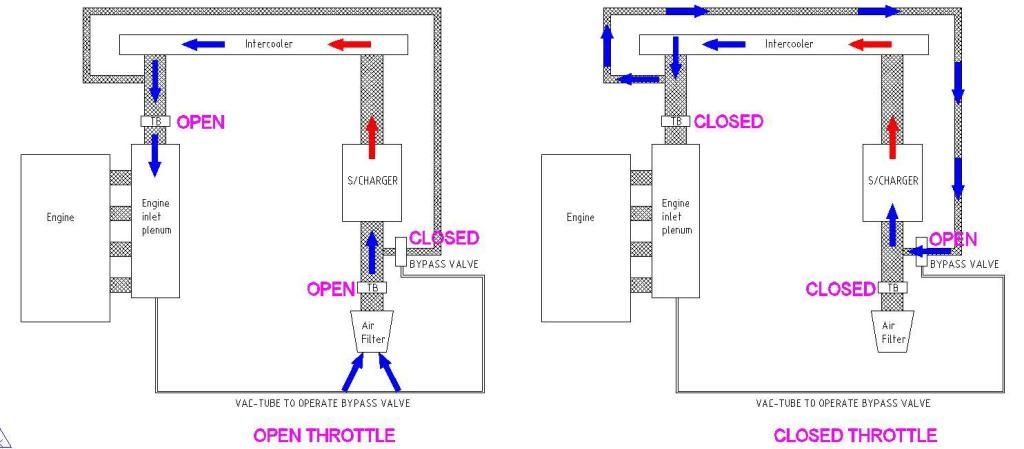
Is the below picture what you mean by recirc valve
If so the valve is open on light or no throttle and shut when WOT. The charger would still be spinning and pushing air even at light/no throttle so
what benefit has it?
Also if there's no air to dump pre tb how come loads of people that have installed these chargers fitted dump valves that do dump air?
https://m.youtube.com/watch?v=Ghjc_I1wQ-g
Sorry if it's all stupid questions. I'm just trying to get my head around it and just when I think I've got it, it's gone haha
rdodger - 10/1/15 at 06:12 PM
That's a bypass from a MINI.
A recirc valve and dump valve are basically the same thing.
Whatever you are using to pump the air, Rotrex, Eaton or Turbo, when the throttle closes you need to get rid of the air between your pump and the TB.
Why? Because the back pressure will at best stall the pump at worst damage the pump.
A recirc valve as the diagram is a quiet way of doing it, but can increase inlet air temp.
A dump valve will give the whoosh and confuse a MAF sensor if you have one.
The MINI bypass lets air past the SC when the inlet manifold pressure is 0 or in vacuum, so no need for a dump vale/recirc as the bypass does the same
job. These set ups tend to be used when the TB is pre charger.
The dump or recirc valve will also connect to the inlet and of course be open when manifold pressure is 0 or in vacuum.
So any of the three does the job.
I hope that helps 
Sierra - 10/1/15 at 07:35 PM
Many thanks that's how I saw it. So with my tb being post blower and recirculating already being proved to create heat my only real option is a
dump valve between intercooler and tb.
Just out of interest how does it work on idle when the charger is still spinning and pushing air towards closed tb, will the dump valve open to dump
the air? Or will it never get to the point where there's to much air to dump?
Also with the above m45 bypass which I've also seen on many charger setups when closing the throttle how does it get rid of the air post blower?
Does it just circulate it back to pre blower, if so then isint all that air still there in the system and not eliminating the problem of too much air
rdodger - 10/1/15 at 07:40 PM
There won't be too much air to dump as by the time you get to that point you will into boost.
As for the M45 question................ er mmm............ yes I guess so
mark chandler - 10/1/15 at 09:56 PM
In the picture above the throttle body goes on the end of the 90 degree mandral bend.
If you run an air to water intercooler and keep the inlet tract short you will not need a secondary throttle body, if you duct to the nosecone and
back with an air to air then you will want one, They just need synchronising and may cost a little power as another restriction for the air to go
through.
mark chandler - 10/1/15 at 11:35 PM
They work on vacumn drawn just after the throttle body, so throttle plate shut you get a high vacumn and the bypass valve is open, medium to heavy
throttle and you have low vacumn so it shuts.
When open the charger is circulating air outlet to inlet, dip your hand in a bowl of water and swirl the water around, it takes a lot of energy to get
up to speed but not much to keep it going, the same applies with the charger so at light throttle valve open it is only drawing a few HP to spin. Open
the throttle and the valve closes, air is now backed up in the inlet (boost) so the charger is now drawing a lot more HP off the crank as it works
against the resistance pushing air into the engine.
HP pinched off the front of the engine is HP you cannot get out the back, I believe my M90 may be pulling as much as 50hp at full throttle which is
why you need a good quality mounting.
You could remove the bypass valve, the car would now consume lots of fuel as it try's to drag air in as well as force it into the engine at light
loads.
Just get one off a mini you should be fine
[Edited on 11/1/15 by mark chandler]
Sierra - 10/1/15 at 11:53 PM
Again many thanks. You've been very patient with my lack of knowledge and explained it very well. Definitely owe you a beer 
I understand that it benefits from recirculating already spun air but I wonder if this benefits as it hot from the charger, instead of the charger
just spinning fresh cool air. I imagine there's probably no way of ever establishing which is best.
Also with just a recirc as above with no dump valve when closing throttle the air will surely just be forced back so some hitting the charger and I
imagine some escaping out the air filter (seeing as my tb is at the plenum)
mark chandler - 11/1/15 at 09:20 AM
With a rootes it displaces air, when you close the throttle it just gets consumed by the engine as there is no excess air to lose.
At low throttle openings the air will be a little hotter as it is being circulated, remember only a few HP is being pulled off the crank so this heat
is minimal once it's been passed by the intercooler, also you are not after making max HP, a few degrees extra heat does not matter.
When you are going full throttle with a rootes charger it consumes a lot of power which is turned into heat, screw or turbine type chargers draw may
30%-50% less power for the same level of boost so are far more efficient and should ultimately produce more power as less being drawn off the crank
and it's cooler.
Sierra - 19/2/15 at 01:32 PM
Small update.
I'm still going a head with the upgrade of the m62 charger. I've found an intercooler that I think I can work with by angling both the
radiator and intercooler, tb wise I've got 2 from standard fords one with a slightly smaller tb plate but larger diameter hose section. The other
has a larger tb plate but smaller hose section, which one would be best?
Also I imagine I'll have to get new injectors as my current ones are the beige 250cc. I'd rather get some and take them with me when the
mapping is done so not to waste time and have to go back.
Thing is I'm not sure which ones to go for as I don't know what power I will get, will getting ones that are too large not work as well?
The power could range from 200bhp to max 300bhp (one day)
theduck - 19/2/15 at 01:51 PM
Too small will result in not enough fuel, too large will mean that the injector is never working efficiently.
beaver34 - 19/2/15 at 02:04 PM
i use astra vxr blue ones, around 440cc i run 3.5 bar static 1-1 raising rate fuel pressure they are good for for 300bhp with no issues
they are also cheap �100 new for a set
scimjim - 19/2/15 at 02:13 PM
injector calculator here
Sierra - 19/2/15 at 09:30 PM
Thanks for the info, according to that site for 250bhp I'll need 450cc and for 300bhp 540cc. If I went for the 540cc then this should cover me
but will they still be too big if I only went with say 250bhp.
Also when searching it's got ohm impedance, which would/wouldn't work on a blacktop?
beaver34 - 20/2/15 at 08:21 AM
quote:
Originally posted by Sierra
Thanks for the info, according to that site for 250bhp I'll need 450cc and for 300bhp 540cc. If I went for the 540cc then this should cover me
but will they still be too big if I only went with say 250bhp.
Also when searching it's got ohm impedance, which would/wouldn't work on a blacktop?
thats not true, 440cc are fine for 300bhp
injectors are rated at say 3.5bar at 440cc but as you increase fuel pressure with boost pressure you get more flow
thats how i understand it anyway
Oddified - 20/2/15 at 10:29 AM
quote:
Originally posted by beaver34
quote:
Originally posted by Sierra
Thanks for the info, according to that site for 250bhp I'll need 450cc and for 300bhp 540cc. If I went for the 540cc then this should cover me
but will they still be too big if I only went with say 250bhp.
Also when searching it's got ohm impedance, which would/wouldn't work on a blacktop?
thats not true, 440cc are fine for 300bhp
injectors are rated at say 3.5bar at 440cc but as you increase fuel pressure with boost pressure you get more flow
thats how i understand it anyway
Not quite, the extra fuel pressure only compensates for the pressure in the manifold (which is working against the injector flow) so the flow stays
the same, ie, balances out.
440cc would be marginal for 300bhp even with a duty cycle of 100% which isn't recomended.
Ian
beaver34 - 20/2/15 at 11:01 AM
quote:
Originally posted by Oddified
quote:
Originally posted by beaver34
quote:
Originally posted by Sierra
Thanks for the info, according to that site for 250bhp I'll need 450cc and for 300bhp 540cc. If I went for the 540cc then this should cover me
but will they still be too big if I only went with say 250bhp.
Also when searching it's got ohm impedance, which would/wouldn't work on a blacktop?
thats not true, 440cc are fine for 300bhp
injectors are rated at say 3.5bar at 440cc but as you increase fuel pressure with boost pressure you get more flow
thats how i understand it anyway
Not quite, the extra fuel pressure only compensates for the pressure in the manifold (which is working against the injector flow) so the flow stays
the same, ie, balances out.
440cc would be marginal for 300bhp even with a duty cycle of 100% which isn't recomended.
Ian
odd as i run 340bhp and i am not maxed out, must be near though
[Edited on 20/2/15 by beaver34]
Sierra - 25/2/15 at 06:55 PM
Small update. I've move the radiator back and tilted it, mounted the intercooler just in front with a couple of top brackets.
I'm a bit concerned about the pipe work going to the top of the radiator now, because of the tilt I've had to fit a tight bend hose that
will then have a 90' bend to original level. Will this still flow ok and allow water to get to the radiator?


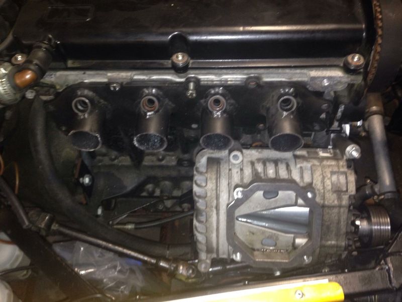
You can see in the below pictures how the inlet ports will need extending and angled to give room for the supercharger underneath.
bi22le - 25/2/15 at 07:20 PM
Any pics of your belt route and how you have tensioned it?
Just thought it would be good as reference ( for me when i start mine!)
Sierra - 25/2/15 at 07:40 PM
Unfortunately no, the supercharger hasn't been mounted yet.
Sierra - 2/3/15 at 10:09 PM
So after a lot more reading it seems that what I originally planned to do with using a bov just won't be the best way.
From the research it seems there are only 2 options that can be used with my setup, both have there advantages but was wondering if anyone can give
anymore negatives as to why one shouldn't be used.
Option1
Or
jeffw - 2/3/15 at 10:46 PM
Just FYI I'm running 660cc injectors at 3.5bar to make 400BHP.
Sierra - 3/3/15 at 08:38 AM
Thanks jeff, yours is a whole different beast lol
Did you have to get a new upgraded fpr
jeffw - 3/3/15 at 11:14 AM
Bosch 3.5Bar fixed FPR. We found the adjustable ones moved around over time which messed the map up.
Sierra - 6/3/15 at 10:54 AM
Right with regards to the above diagrams I've decided to go with a slightly different setup lol
It's now going to be
Air filter > dummy tb > bypass > charger > intercooler > ford tb > inlet
Now I'm using dual tb's because of the large volume of air if only using 1 pre charger. Thing is would I be better having other end of the
bypass valve to charger outlet or pipe after intercooler?
richardm6994 - 6/3/15 at 02:30 PM
Hi Steven,
I've emailed you this diagram which is pretty much what you're saying and what we've been discussing over our emails.......
Sierra - 6/3/15 at 03:40 PM
That's the one thanks Richard.
Be interested to see what people think to this instead of bypass directly into charger outlet.
Sierra - 12/3/15 at 11:46 AM
Any opinions anyone?
old_timbo - 16/3/15 at 12:08 AM
I have a supercharged Pinto. I�m using the standard injection manifold and throttle body, an Eaton M62 blower, BMW mini bypass valve, turbo dump
valve, Megasquirt. The bypass is from the outlet of the blower back to the inlet via the bypass valve. The bypass valve is vacuum actuated from the
inlet manifold. I have a second bypass which uses a turbo dump valve set up as a pressure relief valve which also dumps back to the inlet. Max. Boost
is about 12 psi and the pressure relief valve is set at about 14 psi.
I found that the bypass valve sometimes didn�t open sufficiently to deal with the flow from the blower. This typically happened at 70 mph (3000rpm) on
small throttle openings when cruising. There would be insufficient vacuum to open the bypass. This often resulted in a loud pop as a pipe blew-off.
The pressure relief valve set at slightly above max boost dealt with this. This set-up has given me a good, responsive, linear, throttle.
Incidentally the Eaton is a blower. A blower just moves air from a to b. A supercharger compresses air internally. So in theory when using an Eaton,
other than a small increase due to friction heat soak etc., most of the temperature rise takes place in the system downstream of it where compression
takes place. Therefore taking the bypass- off straight after the charger is not a problem. My inlet air temp. doesn�t increase until I start using the
boost, and it quickly cools down again afterwards.
Sierra - 16/3/15 at 11:00 AM
Thanks for the info. Have you got any pictures of your setup? Also what figures did you get from your setup?
old_timbo - 16/3/15 at 11:29 PM
Just before I took it to get properly mapped the std Pinto pistons died (collapsed ring land). I'd done about 2000 miles blown which was enough
to prove the concept and work up in steps from an initial 3 psi boost. I was hoping for 190 - 200 bhp; certainly went real quick and no need to rev
with all the torque. I've just about finished rebuilding the engine with stronger lower comp pistons (8.3 instead of about 9.7). I'll take
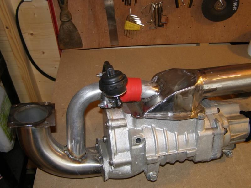
some pictures with it all assembled before I stick it back in. In the mean time I've uploaded a picture of the blower on the bench and what it
looks like in the car (RH 2B). The blower is under the inlet alongside the engine where the dizzy, fuel pump and oil filter usually are, so not easy
to see.
sandwich - 17/3/15 at 11:22 AM
Would the above setup in the picture by richardm6994 work with ITBs like Jenveys or AT?
Sierra - 23/3/15 at 05:22 PM
Can anyone tell me if I'd have to buy arp conrod bolts and also a decompression plate?
Sierra - 16/4/15 at 09:59 AM
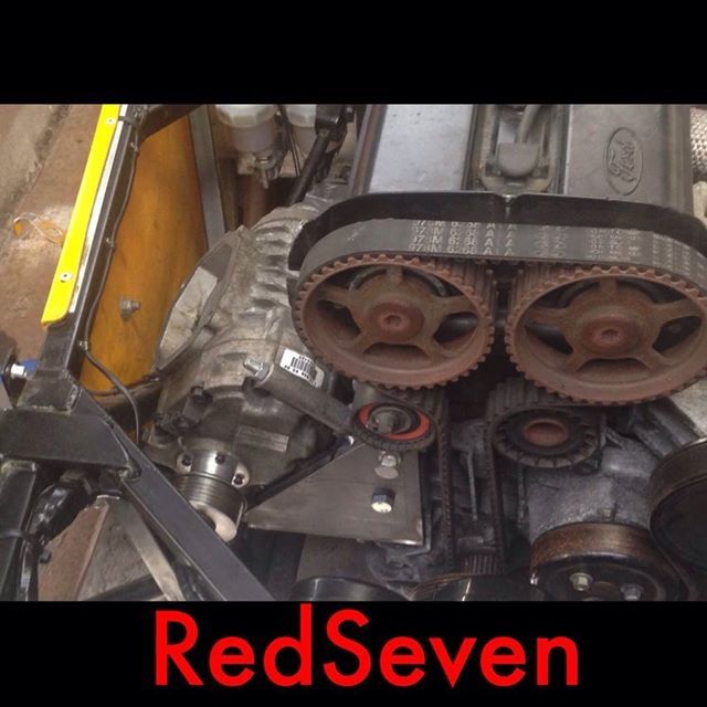
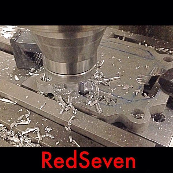
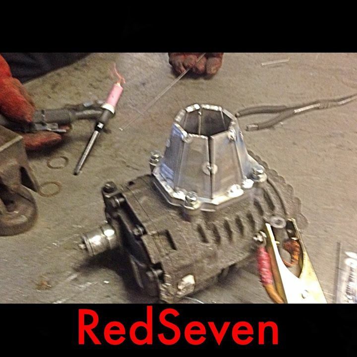
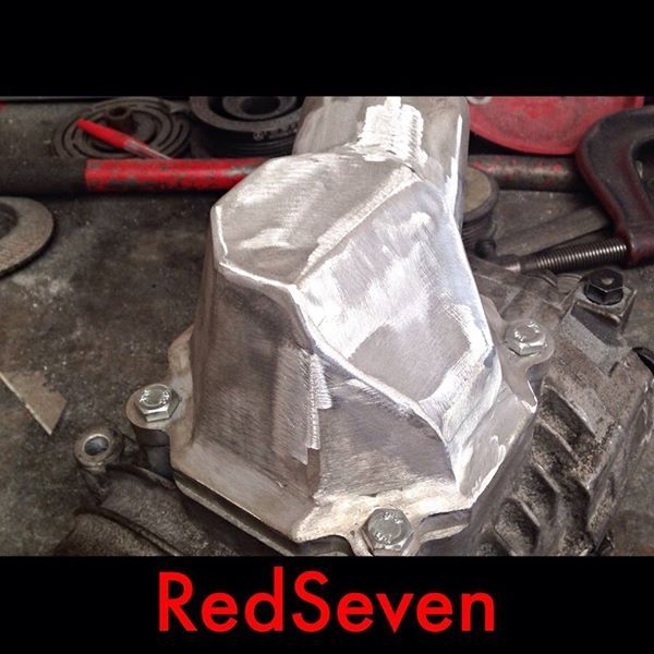
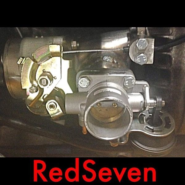
Well the project has now begun and the fun and games of getting the m62 charger mounted.
The car is with Richard at redseven engineering who is currently doing an amazing job and showing how skill full he really is.
Front bracket being made for m62

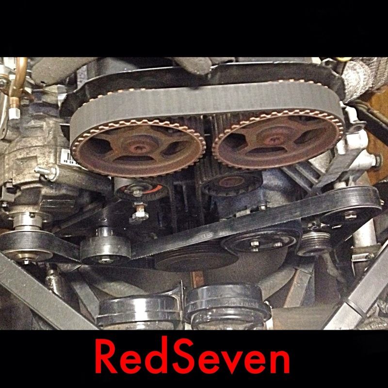
Finished front bracket

Test mounted to the engine
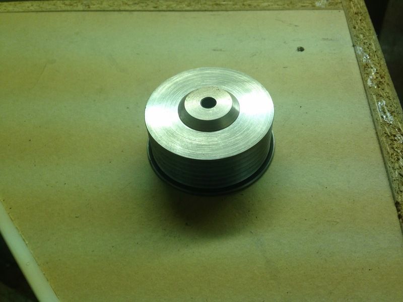
60mm pulley made
[Edited on 16/4/15 by Sierra]
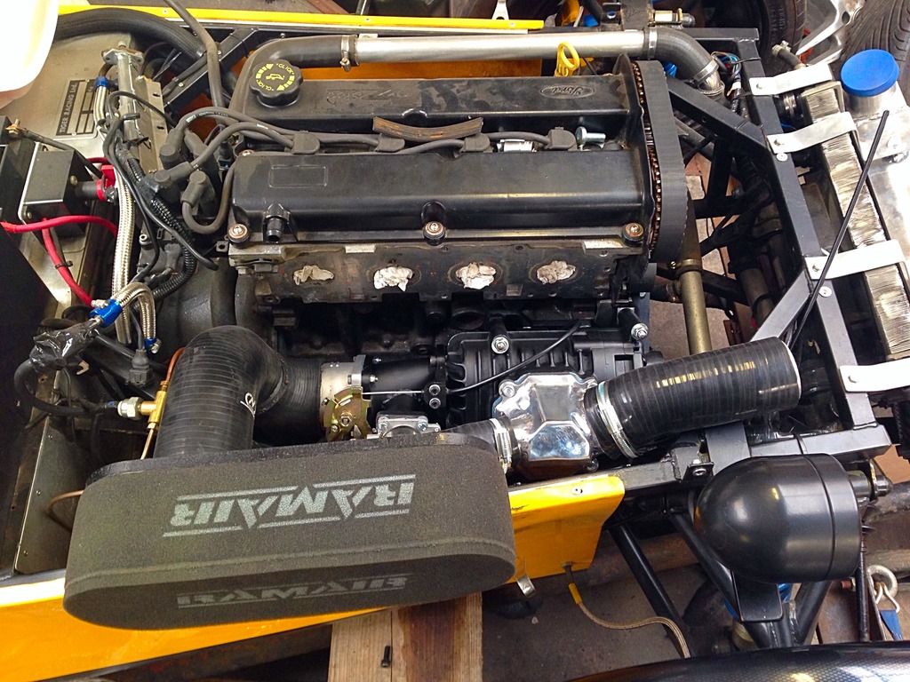
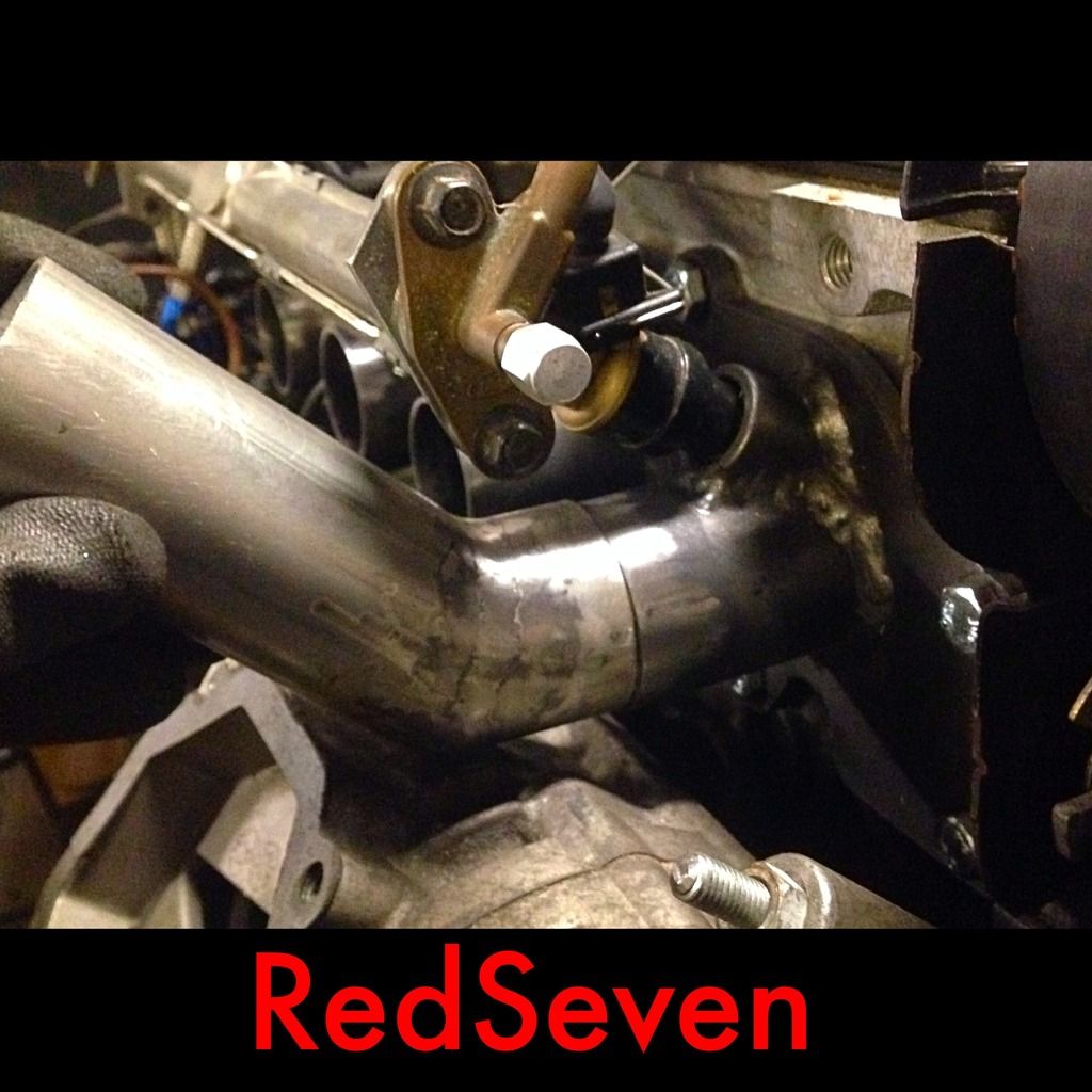
Sierra - 20/5/15 at 09:23 AM
A bit more of an update on the build
Charger fully mounted
All pulleys aligned
Inlet tubes extended at an angle
You can see here that there's some clearance issues for the charger outlet
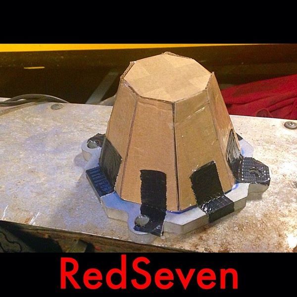
Outlet being made
Mock up and build of outlet
Tube added for recirc valve
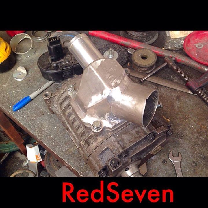
Inlet being made with pre charger tb

With recirc
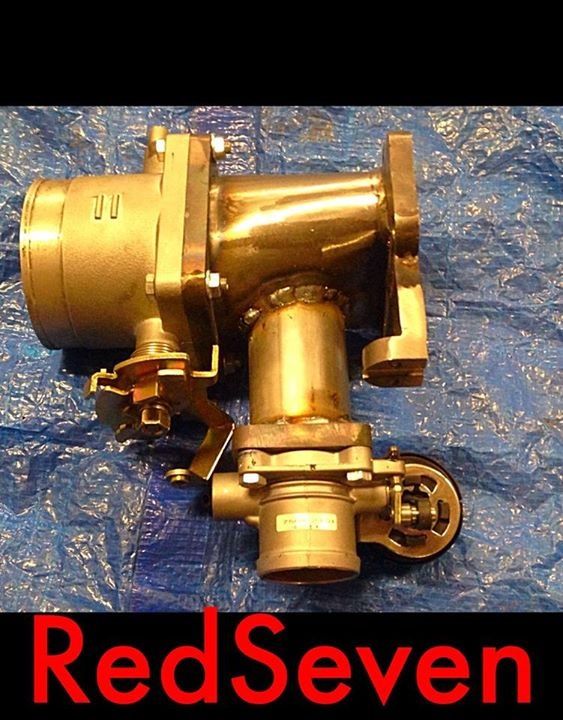
With throttle cable
All in place

Oddified - 20/5/15 at 09:39 AM
Looking good
What is the recirc valve off??.
Ian
rdodger - 20/5/15 at 09:48 AM
quote:
Originally posted by Oddified
Looking good
What is the recirc valve off??.
Ian
BMW MINI
Sierra - 20/5/15 at 08:28 PM
Yes it's from a bmw mini, hopefully that will be all I need.
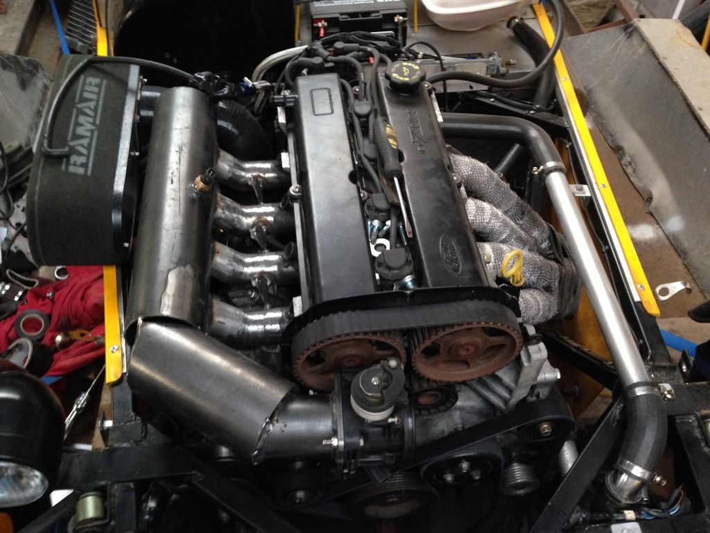
richardm6994 - 30/5/15 at 05:55 PM
Just a couple of photos before the supercharger gets hidden by the engine intake plenum.


jeffw - 30/5/15 at 09:42 PM
Looking good....
richardm6994 - 11/6/15 at 11:07 AM
finally got the engine started yesterday.....I'm going to spend tonight tidying everything up and touching up some paintwork but here's a
short video from last night.......
https://www.youtube.com/watch?v=tpCT09RnM_0
Fcck2000 - 11/6/15 at 11:42 AM
quote:
Originally posted by richardm6994
finally got the engine started yesterday.....I'm going to spend tonight tidying everything up and touching up some paintwork but here's a
short video from last night.......
https://www.youtube.com/watch?v=tpCT09RnM_0
Crikey watch your bloody fingers in that cam belt, made me wince watching your fingers going so close to an open running belt. Get the cam cover back
on ;-)
Looks a really neat installation from what I can see.
Paul
big_wasa - 11/6/15 at 01:41 PM
Any more pictures off the plenum please ?
richardm6994 - 11/6/15 at 01:46 PM
I'll put a few on tomorrow........at the moment, a small petrol spillage ruined it's paintwork and so I've not taken any photos
yet.....repainting tonight so will upload the photos as soon as it's done.
big_wasa - 11/6/15 at 02:32 PM
Thanks. Looks like you have done a lot of work to it.
garyt - 11/6/15 at 06:43 PM
really neat installation , looking and sounding good.
What have you done re your ignition timing and how much boost are you pushing?
Gary
richardm6994 - 11/6/15 at 06:49 PM
Thanks Gary.
The car isnt mine, I've just fitted the charger and made the engine intake plenum. When Steven get's the car home, he'll have the
pleasure of plumbing it all in properly and getting the engine tuned.
richardm6994 - 11/6/15 at 08:41 PM
Ok, here are a few photos of the intake plenum (you can just about see the trumpets I've welded inside.....

big_wasa - 11/6/15 at 09:20 PM
Thanks for the pics. One more question if I can ? Did you make or buy the velocity stacks as its somthing I am looking at for a griffin style manifold
?
Cheers
richardm6994 - 11/6/15 at 09:25 PM
The stacks were bought but I machined down the straight end slightly so that the pushed inside the plenum runners and then a few small welds to secure
them in place.....not that they needed welding as they were a tight fit but better safe as there's no going back once it was all sealed up!!
big_wasa - 11/6/15 at 09:47 PM
Any chance you can tell me what there from ? I was thinking dcoe 40.
Thanks again
Sierra - 12/6/15 at 07:22 AM
Hi I got the trumpets from here
http://www.rallydesign.co.uk/product_info.php?products_id=3336&osCsid=s2llsmsppdu4jujbim5bmsn514
Hope that helps


