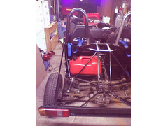
well, heres some piccoes of the car. my favourite first.


bugger it, just deleted the entire thread... what an arse.
well, heres some piccoes of the car. my favourite first.

bollokx...small.jpg)
and the dodgy back end. comments welcome!small.jpg)
Ummmmmm - well, the shock doesn't look like it's got enough travel. Hard to tell much else from that pic.
i think its quite compressed due to the angle its at, so i might well end up bottoming out. Hopefully i'll find out legally one day!
The back end picture is so 'close' you can't really get any proper perspective!
Go on, show us a zoomed out version! 
What does the square rail that goes to the bottom right of the picture do?
Cheers,
James
[Edited on 7/9/04 by James]
Yes could well bottom out like Jasper says , and that top damper bracket has got some serious work to do, generally the damper brackets connect up
under a tube so all the strain is not taken by the welds........
P.S - Do not wish to be annoying or negative , just friendly observations..
is that a standard nose or +4 or something. looks wide in the pic or is it just the angle?
Ned.
The axle subframe tube looks extremely close to the ground, is that it's final position?
Defiately need a wide angle view.
More pics please (can't see how the subframe is attached to chassis or how it's braced).
The Sierra bits don't look very heavy at all, and should be quite spiffy with a coat of paint. Isn't there a kit car that uses the Sierra
rear end intact?
Maybe you'll need a heavier spring; it looks rather compressed considering there's a lot of weight to be added yet. The bracket looks a bit
fragile, too. Is it 1/8"?
Pete
Pete,
some of the tigers use te sierra rear end complete, and believe me, it is very heavy!!
Ned.
pete, it's heavy as a really heavy thing! lol
robin hood uses the full sierra rear doesn't it?
car looks really wide from a front angle joel! deffinalty need more pics though 
Well, if Joel's building the car as a fun kind of runabout, cheap and easy to build (sort of, still a ton of work IMO), then he's spot on.
I see the car as more of a hot rod, and less of a Seven (with all the racing pedigree stuff that implies). Sort of like a RH.
We kibitzers can hold him to a higher standard for the next one. 


Hello all, thanks for the comments.
James - that tube you mentioned is a 19mm square tube that has no greast role than holding in place a simple frame upon which is the plate and lights.
thats the lateral support bit, or one half of...
Dave and pete - the damper bracket is indeed inadequate. I couldnt place it under that bar due to the greater angle and the extra height - but then
the spring compressed so that the height wasnt to high anyway! might fix it. the two supports (circular, going up) are atleast in line with the spring
direction.
Ned - its a wide nose, not sure of the exact dimensions but it is about +4. i got it second hand off a list member. its a bit far forward due to the
very wide car.
im off out for some scran soon, but i'll quickly dig out some photos to clarify the details.
Bear in mind there was no designing involved in this back end, i chopped and welded it many times to get it together. that is the reason why i have a
nearly finished car (i have, honestly!) whilst some other scratch builders are scratching their heads looking at plans - i cut corners. The plan is to
have fun, not to build a record breaking car. anyway, gimme two mins, cos i gotta shrink them all too...
sorry to give you all a crick in the neck...! cant seen to rotate it!small.jpg)
heres the cockpit.small.jpg)
the frontsmall.jpg)
quote:
Originally posted by JoelP
that is the reason why i have a nearly finished car (i have, honestly!) whilst some other scratch builders are scratching their heads looking at plans


oops, i do apologuise pete! that honestly wasnt aimed at anyone except maybe members who have been here for years with no progress!
[Edited on 7/9/04 by Surrey Dave]


Rescued attachment back.jpg
quote:
Originally posted by JoelP
oops, i do apologuise pete! that honestly wasnt aimed at anyoneexcept maybe members who have been here for years with no progress!


quote:
Originally posted by pbura
Things should go swimmingly when I get rid of 5 or 6 family members
 That's a LOT of family members, or are you including the wife and the mother-in-law in the head
count! J/K
 quote:
Originally posted by sgraber
5-6! What!? Are you Mormon or Catholic Pete!?That's a LOT of family members, or are you including the wife and the mother-in-law in the head count! J/K

Will you be concreting the yard soon Pete? In the words of Fred West, " I'm just measuring the wife up for a new
patio"small.jpg)
quote:
Originally posted by Peteff
Will you be concreting the yard soon Pete? In the words of Fred West, " I'm just measuring the wife up for a new patio"


quote:
Originally posted by Peteff
Will you be concreting the yard soon Pete? In the words of Fred West, " I'm just measuring the wife up for a new patio"
 I was a Consultant for the the murder inquiry.

In what field did you consult? Thought you did Telelcomms?
Cheers,
James
Quite a pair the Wests were:
http://www.thisisgloucestershire.co.uk/displayNode.jsp?nodeId=147046&command=newPage
Old Fred was a real DIY type. Potential Locost builder?????
Could this thread have traveled any further OT?
Back to Joel's pics, it's hard to see how the rear subframe is attached to the chassis and how loads are directed. About all that's
visible is the rear diff attachment, which IMO doesn't look very strong if that's the only mounting point.
My frame of reference is the Tiger style IRS, in which the diff sits in a box that is fairly well tied to the rear bulkhead and the shock towers.
Not pretending for an instant to know anything about structures, btw. Just can't see how you did it, Joel. Mind highlighting the pertinent
tubes with Paint or something? If you can't be arsed that's fine 


why should he have to paint his chassis and take more pictures just so you can see how its done?

quote:
Originally posted by liam.mccaffrey
why should he have to paint his chassis and take more pictures just so you can see how its done?


will do pete, gimme a few hours and i'll pull something out of the hat...
pete
this was a very famous set of murders in the UK a wile back. you will find much about it on the internet. Fred West to the UK is like Bundy in the
USA.
cept we didnt fry the f&*ker, he killed himself. Which is just as well, cos with our system, hed be in his own cell watching tv right now. Just
like all the poor young girls he killed are not.
Some were raped as they suffocated with a plastic bag over their head. Nasty little bit of work.
atb
steve
quote:
Originally posted by pbura
Quite a pair the Wests were:
http://www.thisisgloucestershire.co.uk/displayNode.jsp?nodeId=147046&command=newPage
Old Fred was a real DIY type. Potential Locost builder?????
Could this thread have traveled any further OT?
Back to Joel's pics, it's hard to see how the rear subframe is attached to the chassis and how loads are directed. About all that's visible is the rear diff attachment, which IMO doesn't look very strong if that's the only mounting point.
My frame of reference is the Tiger style IRS, in which the diff sits in a box that is fairly well tied to the rear bulkhead and the shock towers.
Not pretending for an instant to know anything about structures, btw. Just can't see how you did it, Joel. Mind highlighting the pertinent tubes with Paint or something? If you can't be arsed that's fine
his own daughter too...
anyway, back on topic!
heres a close up of the shocker mount. maybe needs modifying.small.jpg)
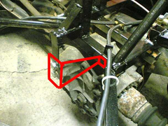
heres the diff back mount. pretty much the same as in the donor, minus the rubber
bit.small.jpg)
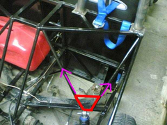
heres the subframe mount, showing the force during acceleration. remember its only a 1.6 pinto! not triangulated but the panel is welded and its only
2 inches above the fully welded floor, and each side is attached to two
uprights.small.jpg)
and finally, the force that matter. the weight of the car and the reaction of the shocker. not perfect but adequate i think.
damn, attachments and beer dont mix...small.jpg)
joel
the acelleration forces will be applied at the diff mounts, not at the front of the subframe.....
thats if im seeing your pictures correctly. If you think about it, the diff would like to rotate, instead of the drive shafts / wheels. The swinging
arm is just kinda hanging there keeping the wheel in place. However, when you apply brakes, the swinging arm will be subjected to a rearwards and
downwards force, as applying the brakes will tend to try and take the swing arem with the hubs.....
atb
steve
Considering Mr. G's remarks about braking forces, I'd be concerned about the subframe trying to pull itself rearward during braking.
Suggestion: 3mm plates on top and bottom of your subframe mounts to spread the loads a bit more.
Also with regard to your diff wanting to rotate, all that's restraining it is a longish vertical tab that might be prone to fatigue. Suggest a
belt-and-suspenders approach, maybe 2mm steel?


Rescued attachment untitled.jpg
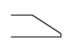
If you want to have longer shockers (or firmer springs on the ones you have), I see nothing wrong with putting the mounting bracket on a gusset
between yiour support tubes:


Rescued attachment untitled2.jpg
could be an idea!
a couple of points though. the diff is attached the the full subframe remember! the little bar only holds it in place vertically, same as the donor.
there will be no twisting force on it beyond what is allowed by the two rubber mounts for the subframe.
also, though i hate to disagree, the acceleration is from the wheel, the wheel pushes the swinging arm, which pushes the subframe, which pushes the
car! if you removed the swing arm the wheel would roll forward without the car.
i like the idea of the gusset though, so i will look into it.
ps, the rubber bit has a 3mm plate for the bottom, similar to donor part but flat. thats getting added as soon as i take the back end off!
[Edited on 11/9/04 by JoelP]
quote:
Originally posted by JoelP
remember! the little bar only holds it in place vertically, same as the donor. there will be no twisting force on it beyond what is allowed by the two rubber mounts for the subframe.


quote:
Originally posted by stephen_gusterson
joel
the acelleration forces will be applied at the diff mounts, not at the front of the subframe.....
Looking at the back end more closely, a lot of the forces are being fed into the rectangular structure at the top/middle of the picture. However,
there is nothing present to direct these forces into the main structure except the welds where the rectangular section is joined to the top tube of
the bulkhead. Some triangulation here is essential I'd have thought, something like the following:

Joel, you've built a beast! 
a monster graham!
longer answers in 10 mins, im off for a pizza! thanks for the input guys.
ok guys, here we go!
pete. the bit that the subframe mounts to is actually stronger than it looks. in short, it is three inch square tubes side by side, fully welded. the
middle one is shorter,and in the end there is a small vertical piece of inch square. across the top at this point is a 3inch x 25mm x 3mm strip, with
a bolt hole thru the middle. this is what the frame bolts to. on the bottom, a large 3mm plate holds the other end of the bolt.
i think triangulating it is a good idea, not because i think there is any chance of an instant failure, but to reduce stress fatigue due to constant
flexing.
mike, there is 4 inches under this point, same as the rest of the car. i might raise the entire car, but 4 inches isnt too far off ok IMO.
Syd, you are entirely correct. this actually occured to me the other day. gonna have to work out how to include the rubber bit on the back. dont worry
about me taking offence, your opinions are always worth hearing even if you are a funny bugger with some people!
 (joking, of course.)
 :p
:p
pete, as for the shape of the back end, i am considering just glueing ply onto it to get it thru the test, then making some fibreglass to do it
properly. the shape will be much as you suggest, just following the bars.
oh yeah, mike, the extra bar you suggest is both needed and exactly what i want to do - but on the n/s it would collide with the fuel tank. i've
thought long and hard about how to do it, but to no avail. the price of not planning i guess. also, i need to work out the braces for the roll bar,
without buggering the rear bodywork. (good photoshopping, BTW!)
still, not too much left now. and at least i can drive it around the yard!
[Edited on 11/9/04 by JoelP]
Joel, just a thought, but if you move the shock upper brackets underneath the attached rail, and connect your fwd subframe mounts to the new shock
mounts and continue this rearward to the rear subframe mounts, you will create a perfect triangle with the shock transmittiong the load to the right
place. The subframe will make the bottom of the triangle.
Are you going to hook up the inner fwd subframe mounts?
Mark
by forward subframe mount, do you mean this? on the donor it doesnt attach to anything.
Rescued attachment untitled.JPG
It was obviously used on something, or it wouldn't be there, Ford cost accountants would have stripped it off unless it was needed.
As it is there and free why not use it to refine your design?
quote:
Originally posted by JoelP
could be an idea!
also, though i hate to disagree, the acceleration is from the wheel, the wheel pushes the swinging arm, which pushes the subframe, which pushes the car! if you removed the swing arm the wheel would roll forward without the car.
[Edited on 11/9/04 by JoelP]
quote:
Originally posted by stephen_gusterson
Imagine this situation - your hand and arm are the swing arm. grease your hand, and hold on to the drive shaft during acelleration (your hand simulates a bearing). No torque forces would go through your hand or arm, the grease/bearing wont allow it.


I agree that there will be a tendancy for the wheel to want to move in an arc, and so the swing arm keeps it in place. However I think thats more of a
load keeping the wheel in position - the main 'equal and opposite' forces will go back into the diff.
My swing arms are actually 40mm (not 50 as i may have said) cos thats what i could get free at the time AND cos I felt that there would be a tendency
for the weight of the car to try and twist the hub inwards, (negative camber).
I also flet at that time that loads did go into the arms - but im not convinced thats a primary load path now.
atb
steve
quote:
Originally posted by JoelP
quote:
Originally posted by stephen_gusterson
Imagine this situation - your hand and arm are the swing arm. grease your hand, and hold on to the drive shaft during acelleration (your hand simulates a bearing). No torque forces would go through your hand or arm, the grease/bearing wont allow it.
quite right, there will be no torque reaction at my hand cos my hand isnt making the driveshaft turn. However, the wheel wants to go forward and all that prevents it going forward is the swing arm. Remember the cv joint would let it roll forward by itself. whilst the diff feels the torque reaction, the swing arm feels the effect of the wheel pushing on the road.
if not, why have you used 50mm swing arms?!
quote:
Originally posted by stephen_gusterson
I agree that there will be a tendancy for the wheel to want to move in an arc, and so the swing arm keeps it in place. However I think thats more of a load keeping the wheel in position - the main 'equal and opposite' forces will go back into the diff.
people keep using this word torque.
its torque that does the work isnt it? where the actual 'push' originates.
If it wasnt for the swing arm, the wheel would like to travel in a circle. SO I can see Joels argument that some forces are transmitted thro the swing
arm to the car. But the actual power originates from the diff, and surely the same twisting forces on the wheel apply at the diff.
The reallt tricky bit to answer, which I doubt can be on here, is what proportion of the engine power is transmitted as a load into the diff, or a
load into the swing arm?
atb
steve
quote:
Originally posted by stephen_gusterson
people keep using this word torque.
its torque that does the work isnt it? where the actual 'push' originates.
If it wasnt for the swing arm, the wheel would like to travel in a circle. SO I can see Joels argument that some forces are transmitted thro the swing arm to the car. But the actual power originates from the diff, and surely the same twisting forces on the wheel apply at the diff.
The reallt tricky bit to answer, which I doubt can be on here, is what proportion of the engine power is transmitted as a load into the diff, or a load into the swing arm?
the "twist" originates at the diff. the "push" originates at the contact patch between the tyre and the road, resisting the "twist". that creates forward force on the wheel, which is resisted by the swing arm (accelerating the car)
so, mike, as I understand you, you are saying that under constant speed in a straight line, the diff is under no loads at all?
we have been talking just in terms of torque - the power is also going down the shaft into the diff. Do you really think that there are no loads on
the diff at all?
ford went well over the top with 8 bolts and that thick diff casing.
atb
steve
Rotational forces and linear forces must always be considered separately. As we all know, every force must be balanced by an equal an opposite one -
the torque at the wheel is balanced by the torque in the diff, hence the need for strong diff casing/mountings. The linear force exerted on the tyre
by the road must be balanced by an equal and opposite linear force somewhere else - in this case from the swing arm via the hub carrier and
bearing.
Cheers
Matt.
Diagram:
Rescued attachment untitled.GIF
matt has it in a nutshell.
quote:
Originally posted by stephen_gusterson
so, mike, as I understand you, you are saying that under constant speed in a straight line, the diff is under no loads at all?
All this science is going over my head a bit, just put a sierra on a rolling road and look at the diff on full accelleration and full braking. its like a wild animal trying to escape, just beef up the brackets a bit.
quote:
Originally posted by James

In what field did you consult? Thought you did Telelcomms?
Cheers,
James


I also agree with matt.
cept no one knows what proportion of the load is exerted at the diff, or the swing arms.
However, both of mine are pretty beefy.
atb
steve
so, not only was fred a murderer, but a cowboy builder too!!!
atb
steve
I know!
the diff feels all the torque, and the swing arms feel all the longitudinal (correct word? non-rotational, anyway) forces
and, expressed in a
'im trying to rip this bit off the car' force, how does that translate?
Sure sounds like the diff wants to do the same thing as the tyres.
atb
steve
quote:
Originally posted by Syd Bridge Also, if you look at how the chassis weight is put to the road, you'll see that the diff has a part to play.
quote:
Originally posted by pbura
2. Freezing them and giving the wood chipper a workout.............


someone had great fun doing a donut at the end of his road last night... allegedly!
my cap pissed of down the road big time. but all in all, lots of fun and nothing broke or bent. if i had a trailer, i would give it some abuse on a
field.
anyway, im getting a 2 litre cos the 1.6 isnt enough, and i may as well change it before registering it...
cheers for the input folk. so far the mods on the cards are sorting the back diff mount, and the top shocker mount. might change the fuel tank too so
that extra bracing will fit. i suspect the boat tank would be difficult to get thru the test, due to removability and the fact that the vent leaks
when upside down.