Airhead
|
| posted on 12/7/10 at 10:59 PM |

|
|
Rear suspension.
So the fun starts; I have decided to replicate the MX5 geometry as closely as I can as the chaps at Mazda designed it to work with my spindles,
driveshafts etc. I measured the mounting points and thankfully they fit within the bounds of the book dimensions so my rear tub will still fit.

These are the mesurements to the mounting points.
I will post up the CAD drawings with measurements soon but for the moment I have output the 3D model I used to check the validity of what I was trying
to do..

The two thin spindles are the "bolts" for the differential - I need to ascertain the hight that it'll sit befor committing but it
looks like it'll sit about 10mm higher than the bottom of the frame. There is a slight offset on the input flange - it sits towards the driver
by about 25mm (guestamate) but it is small enough that it doesn't interfere with the frame.
I've got a little black book with my poems in!
My build diary: http://www.mx5-locost.co.uk
|
|
|
|
|
Airhead
|
| posted on 15/7/10 at 10:41 PM |
|
|
OK a quick update - some mods to the overal design of the rear frame and a set of drawings with dimensions.


I've got a little black book with my poems in!
My build diary: http://www.mx5-locost.co.uk
|
|
|
l0rd
|
| posted on 18/7/10 at 08:13 PM |
|
|
Looking good.
Keep up the good work.
Exactly what i had in mind when i had started drawing mine when i intended to start my build.
|
|
|
Airhead
|
| posted on 30/7/10 at 01:58 PM |
|
|
Things are moving on with the build. I have finished designing the wishbones etc and have drawn them both in my CAD package and 3D to prove that they
work - in my model the rears have a 1.5° negative camber which is exactly the same as the Mazda donor. I have built in some adjustment just in
case.
The 3D ssketches below give some idea of my thinking - the red blobs are placeholders representing the spidle assy.

In this image notice the dogleg in the drivers side SB4. This is necassary because the MX5 diff has the input offeset from the center, a fact taht I
didn't notice until the peice was welded in. It would probably have been better to move that stantion over by 25mm before welding but ce la
vie.


I've got a little black book with my poems in!
My build diary: http://www.mx5-locost.co.uk
|
|
|
Airhead
|
| posted on 22/9/10 at 09:05 AM |
|
|
It might seem that things have slowed down a bit on my build, that's because it has. Not through lack of interest though, I have a couple of
other money making projects on the go that need to be fulfilled in order to pay for parts for the seven.
Back to the build: I have been in communication with John at 3GE Components in Exeter http://www.3gecomponents.com who are making my rear
suspension wishbones to my design and the fronts to theirs - as that is as far as I am concerned in the advanced manual. I believe that subject to
successful testing John will be offering a complete kit for the MX5 donor so watch that space...
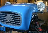
I haven't been totally idle though, I have the diff mount made and have test fitted the motor, to be honest I am over the moon! The only point
for consideration is that the diff is a real bugg.... sorry, pain to get into the chassis as it has great wings protruding from both sides, a bit of
jiggling and some lateral thought and it goes in but how much fun that's be with the car on wheels I don't know. It might be worth making
the cage slightly larger of even designing in removable members...


Appologies for the poor picture quality - Apple should have fitted a decent camera to the iPhone :roll:
|
|
|
boggle
|
| posted on 22/9/10 at 03:36 PM |
|
|
looking good matt
engine may be a bit high up thou?
im over the garage tonight fitting my hubs 
feel free to pop over and say hi as i burn down the house that my ex wife is in 
just because you are a character, doesnt mean you have character....
for all your bespoke parts, ali welding, waterjet, laser, folding, turning, milling, composite work, spraying, anodising and cad drawing....
u2u me for details
|
PLEASE NOTE: This user is a trader who has not signed up for the LocostBuilders registration scheme. If this post is advertising a commercial product or service, please report it by clicking here.
|
Airhead
|
| posted on 23/9/10 at 08:01 PM |
|
|
No checked it out there is 230mm of space under the bonnet and the motor just fits. The Yankee car has the sump 50mm below the rails the same as
mine. It's all good.
I've got a little black book with my poems in!
My build diary: http://www.mx5-locost.co.uk
|
|
|
Mark Allanson
|
| posted on 23/9/10 at 08:09 PM |
|
|
When are you making your bonnet? I have a bit of a track record!
If you can keep you head, whilst all others around you are losing theirs, you are not fully aware of the situation
|
|
|
Airhead
|
| posted on 24/9/10 at 03:23 PM |
|
|
Having seen the quality of your build I'd be stupid not get your help Mark.
I was planning on using Saturn body panels though as I love the way they look - that was my main reason for building to Haynes spec.
I've got a little black book with my poems in!
My build diary: http://www.mx5-locost.co.uk
|
|
|
Airhead
|
| posted on 7/10/10 at 11:44 PM |
|
|
Things are about to get a bit more exciting. I have had some communications from 3GE and it looks like the fronts are well on the way to being
designed and hopefully build soon! Combine that with finalising the rear design to accomodate the shock mount on the lower wishbone and reprofiling
the upper to allow clearance and we might get to see the thing up on wheels soon.. John has sent through the dimensions for the front mounting points
and I hope to get out in the garage and get the jigs made up asap.

The upper shock mount I am going to determine when I have the thing assembled but as you can see there is plenty of scope for it's location.

I have to redraw the CAD drawing showing the rear mounting point dimensions as they have been ammended with the reprofiling of the upper but I will
add them as soon as I have built the suspension and proved it works.
I've got a little black book with my poems in!
My build diary: http://www.mx5-locost.co.uk
|
|
|
Mark Allanson
|
| posted on 8/10/10 at 09:00 AM |
|
|
Matt - that is looking SERIOUSLY good
I have got to see this at some point
If you can keep you head, whilst all others around you are losing theirs, you are not fully aware of the situation
|
|
|
Airhead
|
| posted on 9/10/10 at 08:06 PM |
|
|
Thanks Mark
Pop up and see it anytime you like, she's still just a chassis at the moment but hoping that the wishbones will arrive soon - then I can really
crack on.
Matt
I've got a little black book with my poems in!
My build diary: http://www.mx5-locost.co.uk
|
|
|
AntonZdz
|
| posted on 19/10/10 at 08:45 AM |
|
|
Wow!
This looks like a really well thought out project. I too am working on a MX5 based Locost, my problem is the Donor car is my Daily at the moment . I
was wondering, if you arent too far away if you could talk me through some adjustments and measurements you have done for this over the standard over
a Beer or two (at my expense of course).
[Edited on 19/10/10 by AntonZdz]
|
|
|
Airhead
|
| posted on 19/10/10 at 12:02 PM |
|
|
Hi
I am only too happy to help out where possible, bearing in mind I am no expert...
There is a subtle difference in the track of the MK1 and MK2 MX5s IIRC - I don't know if this is in the wishbones or the mounting points.
May I ask, if you are driving this donor currently then it can't be that bad - would it make more sense to sell it and get a MK1 donor as there
is a fair bit of work already done getting the MK1 gear to fit and 3GE in Exeter are actually producing a wishbone kit to fit. I picked my V-Spec MK1
up for a couple of hundred pounds.
The other school of thought is that it is good to push the boundaries so go for it and develop a locost based on the MK2
BTW I am building based on the Haynes Roadster because I plan to use Saturn body panels, the dimensions of the rear mounts will still be the same for
the book chassis if you plan to go that way.
Forgot to ask where you are based BTW?
Matt
[Edited on 19/10/10 by Airhead]
I've got a little black book with my poems in!
My build diary: http://www.mx5-locost.co.uk
|
|
|
AntonZdz
|
| posted on 19/10/10 at 01:07 PM |
|
|
I am Hampshire based!
The MX5 isnt in a bad condition mechanically wise but the history and body work are pretty awful after the last owner, so I thought why the hell not
just go for it. My chassis is being built off the Haynes Roadster book. In terms of the wishbones and suspension setup this is something I am looking
into currently I was more looking for engine, gearbox and diff mountings. I have replied on the Haynes forum aswell so I am happy to chat with you on
which ever you prefer?
|
|
|
Airhead
|
| posted on 31/12/10 at 12:04 AM |
|
|
Wishbones
I finally have my wishbones! Big thanks to John at 3GE Components http://www.3gecomponents.com/templates1/index.php?site=63 the standard
of the workmanship is outstanding and really has to be seen in the flesh to appreciate it.


I still can't take the suspention build forward as I need to get a hold of the bushes but I have laid the components out and thankfully my
calculations and design for the rear seems to be sound. Phew.
I've got a little black book with my poems in!
My build diary: http://www.mx5-locost.co.uk
|
|
|
Airhead
|
| posted on 31/12/10 at 12:52 AM |
|
|
Whilst I wait to sort the bushes for the suspension I have decided to have a look at the mounting points for the engine and gearbox. Those Japanese
folks are pretty clever really and everything in the drivechain is mounted simply which has made the process quite simple so far. The rear-most
gearbox mount sits level with the top side of the lower tunnel rail which makes a good start, in this position the gearshift sits nicely in position.
The front gear box mount will be sorted once the engine is sitting level.
In a previous life I was in to Land Rovers, tinkering with 90's led me to the perfect solution for the engine mounts. The Mazda parts on my
donor were shot as the engine had been suspended from them when the car inverted and the rubber parts had ripped so they were ditched. A quick search
through the parts box found a pair of Defender TD5 gearbox mounts which are almost exactly the correct angle to convert from the Mazda OEM brackets to
the top side of the lower rail. As a bonus there is even a little pin on the Landrover part which locates into the hole in the Mazda bracket!

This image shows the OEM bracket attached to the TD5 gearbox mount, the engine is suspended in this shot. You can also see the additional rail which
has been welded in to bear the weight.


My 3d design sketches prove invaluable as I am able to save time and metal by making mistakes on the PC first.


These images show the finished brackets clamped in place with the engine supported on them, tomorrow I'll whip the engine back out and weld it
all together.
I've got a little black book with my poems in!
My build diary: http://www.mx5-locost.co.uk
|
|
|
RoyzMG
|
| posted on 3/1/11 at 03:33 AM |
|
|
Miata Build
Airhead-
I've been following your build diary at http://www.mx5-locost.co.uk/ but can't find any way to get a hold of you to ask questions or
make comments.
I'm also doing a Miata build but in the US.
I noticed your chassis status and have one question - How do you plan to install the Miata differential?
Thanks,
Roy (RoyzMG)
|
|
|
Airhead
|
| posted on 3/1/11 at 02:54 PM |
|
|
Hi Roy,
My inspiration came from looking at the US sites; so it goes full circle
The diff will be suspended from the two plates with good strong bolts, IIRC 12mm fits the holes in the dif nicely. I then intend to hold the front of
the diff firmly with a plate welded across the tranny tunnel and one higher up through which I'll put another two big strong bolts. From what I
understand the nose of the diff is the area to concentrate on as the torsional force is greatest there. on the MX5 there is an alloy spacer which I
hope to use on the front of the diff allowing the mounting plates to be a bit further apart which should ease fitting a bit.
I'll try to find some time to draw what I was planning on the 3d model later.
Matt
I've got a little black book with my poems in!
My build diary: http://www.mx5-locost.co.uk
|
|
|
RoyzMG
|
| posted on 3/1/11 at 03:56 PM |
|
|
Getting Diff. Into Place
Thanks Matt-
I think I understand how you plan to mount the differential but what I was really wondering is how do you plan to physically get the differential
piece into place. It looks like you have all the welding done at the back. The differential is a very ackward shape and heavy so how does it fit in
between the lower tubes and up into place? Reversely how do you remove the piece?
The odd shape is a problem. Some designs use removeable pieces to allow installation and removal for repair. Is this your thought?
Thanks,
Roy (RoyzMG)
|
|
|
atm92484
|
| posted on 3/1/11 at 04:28 PM |
|
|
Great looking build Matt.
What are your plans for mounting the diff snout? It seems to be the Achilles heel for many Mazda-based 7s.
[Edited on 3/1/11 by atm92484]
-Andrew
Build Log
|
|
|
Airhead
|
| posted on 4/1/11 at 10:33 AM |
|
|
Hey Guys
Roy - sorry mate, I totally misunderstood... There is enough room for me to roll the diff in from the bottom sideways with one arm through the top
then putting the lower arm in place rolling the diff back round to level. The downside is that I'll need to remove the fuel tank in order to do
this in the completed car. I had toyed with making the lower rails removable but bracing the tops as well so that there isn't too much
deformation in the rear frame. I'll post up the pics later when I'm back home.
Andrew - Absolutely right, the nose of the diff is the weak point. I was trying to explain my design in an earlier post but if you watch this space
I'll try to get a 3d sketch posted asap.
Matt
I've got a little black book with my poems in!
My build diary: http://www.mx5-locost.co.uk
|
|
|
Airhead
|
 posted on 19/3/11 at 12:04 AM posted on 19/3/11 at 12:04 AM |
|
|
Front Suspension
I have finally got all of the bits together along with some time so have made some progress. Using a combination of the dimensions from the book and
those relevant to the 3GE arms I made a jig akin to that in the book and attached the suspension brakets:
The jig is paramount to accuracy so I started by making a wooden jig to make the jig proper.


I modified the design just slightly by using nuts on the threaded bar in place of the spacer bar; this allowed me to dial in the position of the
brackets accurately 
With the brackets in place they were welded on shortly followed by the arms and spindles.


Tomorrow we get the rears on.
I've got a little black book with my poems in!
My build diary: http://www.mx5-locost.co.uk
|
|
|
loggyboy
|
| posted on 19/3/11 at 12:41 AM |
|
|
Looks like ur having lots of fun with this build. Almost makes me wish I was doing a 'scratch build'.
One query, how do you plan on paneling ur tunnel now you have added the kinks? would it not have been easier to straight line the tunnel rather than
adding the kink?
|
|
|
Airhead
|
| posted on 19/3/11 at 09:28 PM |
|
|
It would have been easier but the kinks are necassary to accomodate the gearbox and allow the seat to adjust.
Matt
I've got a little black book with my poems in!
My build diary: http://www.mx5-locost.co.uk
|
|
|