Rudy
|
| posted on 13/10/06 at 04:47 PM |

|
|
Bump steer optimized by cheap laser pointer
Hi friends,
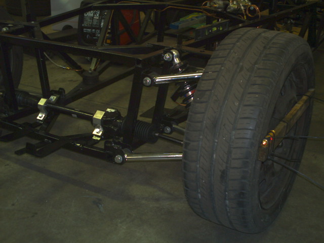
With your helps I have optimized ackermann angle. And then by using a laser pointer (cost 4,00 euro) I have optimized bump steer.
What do you think?
Laser point farward to a wall that is 550 cm far. By mooving car up an down I have a movement of 5 cm on the wall.
Isn't it excellent?
Thank you again all!
Sorry about my English
|
|
|
|
|
Rudy
|
| posted on 13/10/06 at 04:50 PM |

|
|
A foto
 
Rescued attachment IMAG0088.JPG
Sorry about my English
|
|
|
Rudy
|
| posted on 13/10/06 at 04:51 PM |

|
|
many sorry for the foto dimensions
Sorry about my English
|
|
|
kb58
|
| posted on 13/10/06 at 06:06 PM |

|
|
I thought about doing this myself... but don't think it'll work.
Both the upper and lower a-arms move through arcs, right? Moving together, attached to the upright, the wheel moves through an arc also, right?
Because of this you can't tell the difference beween the wheel moving sideways due to the arcs, and bumpsteer.
So even if you have zero bumpsteer, the laser will draw a curved line on the wall. I think a laser can be used to measure it in some way, I just
don't know how.
BTW you can open your picture in Microsoft Paint and reduce its size with Image/stretch/skew.
[Edited on 10/13/06 by kb58]
Mid-engine Locost - http://www.midlana.com
And the book - http://www.lulu.com/shop/kurt-bilinski/midlana/paperback/product-21330662.html
Kimini - a tube-frame, carbon shell, Honda Prelude VTEC mid-engine Mini: http://www.kimini.com
And its book -
http://www.lulu.com/shop/kurt-bilinski/kimini-how-to-design-and-build-a-mid-engine-sports-car-from-scratch/paperback/product-4858803.html
|
|
|
MikeRJ
|
| posted on 13/10/06 at 09:07 PM |

|
|
quote:
Originally posted by kb58
So even if you have zero bumpsteer, the laser will draw a curved line on the wall. I think a laser can be used to measure it in some way, I just
don't know how.
How about taking a baseline measurment with the track rod disconnected from the upright? Only thing is would the uprights stay pointing the same
direction as you move the suspension up and down...probably not, especialy with new (tight) balljoints. Could probably lash up some kind of bracket
to stop the upright moving though.
Alternatively you could be clever about it. Given the wishbone lengths and locations, the arc described with zero bump steer could be calculated and
plotted out.
|
|
|
Geoff011
|
| posted on 14/10/06 at 12:01 AM |

|
|
If you used 2 lasers it would work. One in the position shown, and one at the trailing edge of the tyre. Stagger the heights so that the front one
doesn't block the beam from the rear. Plot both curves and if there is a variance, you've got bump steer.
Not a real accurate way to measure it, but will show up any major issues.
|
|
|
Rudy
|
| posted on 14/10/06 at 06:30 AM |

|
|
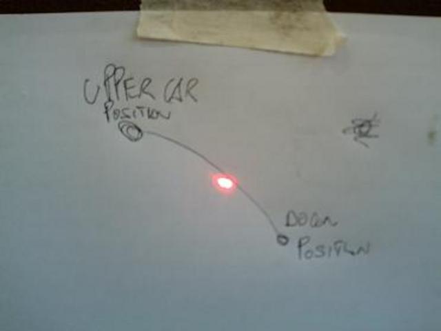
This is the drawing of laser.
"How about taking a baseline measurment with the track rod disconnected from the upright?" I try it but wheel moves a lot himself when I put
up and down the car.
BTW, MikeRJ, I read somebody use a laser pointer from an old post of yours. Did you remeber? So I use laser becouse YOU gave me this idea. I think it
is a good method to have an idea how much bumpsteer we have. In the beginning I put steering rack in a higher position and I had lot of bumpsteer.
Thanks
 
Rescued attachment IMAG0001.JPG
Sorry about my English
|
|
|
Rudy
|
| posted on 14/10/06 at 06:34 AM |

|
|
Geoff011, I do not understand very well how to do with 2 laser. (I do not understand english very well) May you tell me with other words?
Sorry about my English
|
|
|
907
|
| posted on 14/10/06 at 07:05 AM |

|
|
Hi
If the laser was mounted on the wheel rim facing sideways,
would this then draw a vertical line if there was no bump steer?
Paul G
 
Rescued attachment laser-s.jpg
|
|
|
Rudy
|
| posted on 14/10/06 at 09:06 AM |

|
|
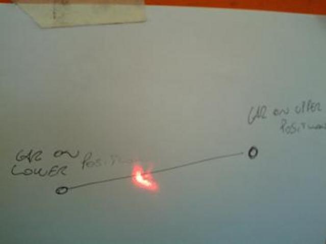
I put laser as Paul G explain.
Laser point a wall far about 700 cm from Wheel.
This is what laser draw on the wall.
P.S. This drawing is referred to left wheel the first drawing is about right wheel.
 
Rescued attachment IMAG0003.JPG
Sorry about my English
|
|
|
t.j.
|
| posted on 14/10/06 at 09:35 AM |

|
|
I would mount one on top of the bottom wishbone as far as possible to the upright.
Then use a second one at the outside of the tyre. And put this one at te same height above ground as the one on your wishbone.
The one inside is your reference.
Grtz Theo
[Edited on 14/10/06 by t.j.]
|
|
|
907
|
| posted on 14/10/06 at 09:57 AM |

|
|
When I positioned my rack I jacked up the chassis and put it on blocks, removed the shock,
and knocked a wooden wedge in the caliper / disc to stop the wheel rotating.
Then lift the wheel through it's full travel.
If you bounce a car on it's suspension the wheel tries to rotate and gives a false reading.
I'm no expert but it seemed to work for me.
Paul G
|
|
|
MikeRJ
|
| posted on 14/10/06 at 11:30 AM |

|
|
quote:
Originally posted by 907
Hi
If the laser was mounted on the wheel rim facing sideways,
would this then draw a vertical line if there was no bump steer?
Paul G
That would be the ideal method, but makes mounting the laser a little more awkward. You could probably use one of the tiny laser pointers and use
e.g. a jubilee clip to attach it to one of the wheel studs.
|
|
|
Rudy
|
| posted on 14/10/06 at 02:13 PM |

|
|
Of course dumpers are disconnect (bottom), in the foto seems damper are fix. In the foto you see only upper brackets
Sorry about my English
|
|
|
whittlebeast
|
| posted on 14/10/06 at 02:15 PM |

|
|
These work great.
http://cgi.ebay.com/Magnetic-Laser-Level-Screwdriver-Set-New-Christmas-Item_W0QQitemZ300037560227QQihZ020QQcategoryZ43588QQtcZphotoQQssPageNameZWDVWQQ
rdZ1QQcmdZViewItem
Just block up the chassis and remove the shock and wheel. Put a brick on the brake pedel to keep the disk from turning. Stick the laser on the disk
and move the tire up and down. Watch the dot on a wall 15 feet in front of the car compared to 2 feet in front of the car. Remember that the disk
will move in and out as the suspension moves up and down. It's the angle that is important.
|
|
|
t.j.
|
| posted on 14/10/06 at 08:24 PM |

|
|
quote:
Originally posted by whittlebeast
These work great.
http://cgi.ebay.com/Magnetic-Laser-Level-Screwdriver-Set-New-Christmas-Item_W0QQitemZ300037560227QQihZ020QQcategoryZ43588QQtcZphotoQQssPageNameZWDVWQQ
rdZ1QQcmdZViewItem
Just block up the chassis and remove the shock and wheel. Put a brick on the brake pedel to keep the disk from turning. Stick the laser on the disk
and move the tire up and down. Watch the dot on a wall 15 feet in front of the car compared to 2 feet in front of the car. Remember that the disk
will move in and out as the suspension moves up and down. It's the angle that is important.
You will measure in front of the car also the arc of camberchange. As your/my upper wishbone is shorter you will not get a vertical line!
So probable or an reference laser extra in front or as Paul and mike RJ mentioned 90 degr on wheel.
I think now the 90 degr option is the best one!
[Edited on 14/10/06 by t.j.]
|
|
|
kb58
|
| posted on 14/10/06 at 09:27 PM |

|
|
The trouble with the laser point laterally is it'll show caster, anti-dive, AND bump steer. I'm still not sure how to separate the other
two to only show bump steer. It keeps coming back to using the vertical board method riding on the wheel rims. I don't have a clever way around
that method yet...
Mid-engine Locost - http://www.midlana.com
And the book - http://www.lulu.com/shop/kurt-bilinski/midlana/paperback/product-21330662.html
Kimini - a tube-frame, carbon shell, Honda Prelude VTEC mid-engine Mini: http://www.kimini.com
And its book -
http://www.lulu.com/shop/kurt-bilinski/kimini-how-to-design-and-build-a-mid-engine-sports-car-from-scratch/paperback/product-4858803.html
|
|
|
MikeRJ
|
| posted on 14/10/06 at 10:52 PM |

|
|
quote:
Originally posted by kb58
The trouble with the laser point laterally is it'll show caster, anti-dive, AND bump steer.
Anti-dive, yes I agree it would be affected by this, though not a problem for 99.99% of locosts (I appreciate you don't have a locost though!).
I'm not convinced about it beng affected by castor though. If the upper and lower wishbone pivots are parallel with each other in both possible
planes, I can't see that any castor would impart a non-linear motion to the upright over the suspension travel. I could be wrong, but I'd
like to understand why if possible.
|
|
|
kb58
|
| posted on 15/10/06 at 01:45 AM |

|
|
Eh... you are correct... I think. I guess I have to think about it more myself.
Mid-engine Locost - http://www.midlana.com
And the book - http://www.lulu.com/shop/kurt-bilinski/midlana/paperback/product-21330662.html
Kimini - a tube-frame, carbon shell, Honda Prelude VTEC mid-engine Mini: http://www.kimini.com
And its book -
http://www.lulu.com/shop/kurt-bilinski/kimini-how-to-design-and-build-a-mid-engine-sports-car-from-scratch/paperback/product-4858803.html
|
|
|
gazza285
|
| posted on 15/10/06 at 02:41 AM |

|
|
quote:
Originally posted by t.j.
I would mount one on top of the bottom wishbone as far as possible to the upright.
Then use a second one at the outside of the tyre. And put this one at te same height above ground as the one on your wishbone.
The one inside is your reference.
Grtz Theo
[Edited on 14/10/06 by t.j.]
Doesn't work as the reference should be at the wheel centre not the bottom pivot.
The way is to have the distance between the points plotted by the lasers at the wheel centre and the dynamic track measurement. Trouble is the dynamic
track measurement is hard to measure because of the KPI, Ackermann angle and camber. And this is just to set it at zero steering angle, let alone at
any turn angle.
Caster does not change, camber does which makes the laser pointer irrelevant unless at the centre of the wheel, so fastening it to the disk or wheel
rim is no good unless dead central. Fastening it parallel to the stub axle would make more sense.
DO NOT PUT ON KNOB OR BOLLOCKS!
|
|
|


