Anyone fitted driveshafts to the Muffett TSR 300IL?
sucksqueezebangblow - 8/6/08 at 03:29 PM


Drive Shaft
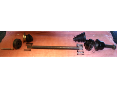
I'm trying to fathom how the drive shafts assemble to the sierra stub axle and Muffett TSR 300IL differential.
It is pretty clear how the outboard end goes; driveshaft through boot, then through CV joint and held in place by circlip on end of shaft. Then 6
bolts through metal part of boot, through CV joint and into threads on stub axle. Grease liberally and Robert's your father's brother. (But
please feel free to correct me if I'm wrong)
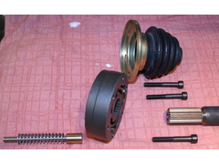
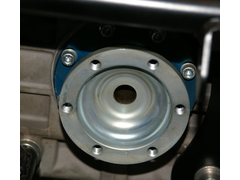
The inboard end is what bothers me. A piston, rod and spring are supposed to go into the centre of the output flange but it is not clear how, or how
you determine the length of the rod (which I'm told should be shortened to position the driver shaft).
The face of the piston is concave, I'm told is in order for it to mate with the end of the driveshaft, but there is no convex face on the
driveshaft, the driveshaft is a larger diameter than the piston, and the driveshaft is hollow. Normally it is possible to work out how parts go
together but to be honest, this time I'm flummoxed and am beginning to think some parts must be missing or wrong.
Assuming someone is able to help me with the plunger problem, the other issue is that the splined end of the shaft is considerably longer that the
mating splined centre of the CV joint meaning that the centre of the CV joint will be able to slide on the shaft! This can't be right can it?
Both latteral movement in the CV joint (which is what it is designed for) and in the shaft in sliding through it. It sounds like a recipe for
disaster!


Drive Shaft Inboard


Diff Output Flange
PS RoadWarrior, i've sent you an email as I suspect you are an expert on this subject!
[Edited on 8/6/08 by sucksqueezebangblow]
tks - 8/6/08 at 04:19 PM
did you look if the shaft has an hole in one end where the remain end of the spring axle inserts???
i think the bigger part is on the outside and the spring in the inside pushing the shaft outwards..
then the bolts and the boot are easy to do..
cant you find nothing o the net where did you buy the stuff??
Tks
marc n - 8/6/08 at 04:52 PM
quote:
PS RoadWarrior, i've sent you an email as I suspect you are an expert on this subject!
i was just going to suggest that 
road warrior - 9/6/08 at 01:02 PM
Clive
I have sent you an email, I hope it is of some assistance.
Cheers
Sonja
sucksqueezebangblow - 10/6/08 at 12:46 PM
Thanks Sonja, you're a star!!!
PS keep the YouTube footage coming and congrats on four wins out of four!!!
sucksqueezebangblow - 11/6/08 at 05:42 PM
For anyone interested in the outcome the solutions are as follow;
The first issue is addressed by pressing domed inserts into the inboard ends of the gun drilled driveshafts. They arrived today from Muffett (thanks
Neil). The inside surface of the stub axle limits travel in the other direction.
The second issue may not be an issue as Redback Racing run their shafts with the inboard splines free to slide in the CV joint centre with no issues
with that so far.
It is likely that the longer than necessary splines on the inboard end of the shaft are intended to allow some adjustability in the final length of
the driveshaft, and once the required length is established circlip grooves can be machined into them and indeed length machined off if necessary.
Based on Redbacks experience I think I will need the full length but will check once the the suspension is set up with the correct camber.
MikeRJ - 11/6/08 at 06:10 PM
Surely the longer splines are to allow the drive shaft to plunge within the CV joint as the suspension moves, since that type of CV joint doesn't
have any plunging capability (unlike, e.g. tri-pode type).
If this is the case there should be no circlip groove machined, and no circlip fitted to the end with longer splines.
sucksqueezebangblow - 12/6/08 at 08:31 AM
Ahh, then you may know something I don't.
The CV joints I have are Fiesta inboard joints. They are held by a cable tie for transporting/handling because the centre section of the joint can
move a considerable distance out from the middle of the joint in either direction. My understanding is that this movement is intended to allow the
driveshaft to move as the suspension goes from horizontal to full bump or droop.
Anyone have the definitive answer? Is the centre of the Fiesta inboard CV joint intended to move in and out of the main body of the joint or to stay
central with no in or out movement? (by in or out I mean movement along the line of the axis of the drive shaft)
Clive.
[Edited on 12/6/08 by sucksqueezebangblow]


