Ivan
|
| posted on 25/6/12 at 08:13 AM |

|
|
Designing Fuel Injection System for 6.4 litre SBC - a personal journey
This is posted as a reminder to myself of my thought processes and a reach out to anyone else going through this process on any motor, I will add to
this as I progress! Any comment or advice will as always be welcomed.
Background:
I have a newly built 383 SBC (Small Block Chevy) in my 23 year old Cobra and have decided to convert it to fuel injection in an effort to reduce fuel
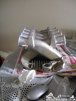
consumption and increase power, to this end I have purchased a cross ram manifold suited to 4 X Webers plus 8 velocity stacks which gives a lovely
straight run to the inlet valves, so I have taken the first step on this road - have the manifold and some velocity stacks.

I had to go through the process of deciding whether to use individual throttle bodies or two Plenums fed by two single throttle bodies. In the end I
decided that, after driving the car on just the plain and simple Holley 600 CFM with Vacuum Secondary's, the last thing I wanted was instaneous
throttle response. It was already too easy to let the torque get away from you at takeoff when the car was pointing in anything but straight ahead or
when road friction was even marginally compromised. The result of this experience has convinced me that shared smallish throttle bodies feeding a
plenum would give a much more controllable power to throttle depression response. The above thinking is based on the reality that 90%+ of the
car's usage will be on public roads and 10%- on track days.
Plenum Design:
My choice of two throttle bodies feeding into two plenums had at first sight (very uninformed so it appears now) always seemed to me to be the
simplest solution with few down sides, however now that I have to do it, I have done some research on Google and things are far from simple.
It appears that with using the normal plenum design with the air entering through the TB from one side and the plenum tapering down towards the other
it is almost impossible to get anywhere near even flow distribution to all the cylinders without very sophisticated design tools and an equally
sophisticated understanding of what you are doing using those tools. This is beyond my time and skill levels to undertake so Google became my friend
again.
The following site gives some idea of the problems involved and possible impacts and served as a useful introduction to my education on plenum design
issues.
http://josephrinek.com/intakemanifold.html
I then found the forum thread below that ended up in informing my final decision on plenum shape.
http://forums.hybridz.org/index.php/topic/61549-turbo-intake-plenum/
After much thought I will be going for a shape informed by "Montzer's" work and illustrated on page 7 of the thread. I will make it
up with foldable, rolled and/or welded panels.
http://forums.hybridz.org/index.php/topic/61549-turbo-intake-plenum/page__st__120
Inlet Runner Length:
Right that's the plenum shape decided upon, now to decide on inlet runner length.
Again it's back to Google and one of my favorite authorities Dave Walker. From his writings it appears that longer is better in most
circumstance, a check on
http://www.eng-tips.com/viewthread.cfm?qid=165529
shows that various formulae can be used to calculate optimum length and in fact further reading will lead one to total confusion. However using the
following formulas obtained from the above url.
84,000 / tuned rpm = runner length in inches
and
Runner Length in mm = (90 X 334)/(RPM X 0.012)
the runner length comes out at around 500+ mm which will be difficult to achieve, so I will go as long as space allows. I should be able to achieve
around 450mm.
Injector Size & Type:
Now for the selection of the injectors - because I do not have the turbulence that ITB's throttle plates create at partial throttle (and to some
extent at full throttle) I have decided to steer clear of single hole injectors and go for four hole one's that have a better spray pattern to
promote air/fuel mixing. On-line calculators indicate that I should use 40lb/hr injectors at 43.5psi fuel pressure but I might well decide to use 36
lb/hr ones at a higher pressure that might improve mixing (still thinking about that one - not sure if my theory is right???).
Throttle Body Size:
To size the throttle bodies I returned to Google and found the following that seems to make good sense and I will test it when I have time to study it
and set up a suitable spreadsheet.
http://www.lxforums.com/board/f88/throttle-body-selection-pocket-calculator-194536/
In the meantime I used the equation found at the URL below - I calculated for 75% of the speed of sound and got 2 X 70mm diameter throttle bodies
which seems reasonable. At 100% of speed of sound I get 2 X 60mm throttle bodies. The figure of 75% is just something I sucked out of my thumb as I
think using 100% is too close to the limit and the calc doesn't allow for turbulence and area reduction caused by the throttle plate itself.
http://www.hipermath.com/engines/throttle_body_size
|
|
|
|
|
Confused but excited.
|
| posted on 25/6/12 at 09:57 AM |

|
|
Nice one. Very ineresting post.
Tell them about the bent treacle edges!
|
|
|
mark chandler
|
| posted on 25/6/12 at 11:37 AM |

|
|
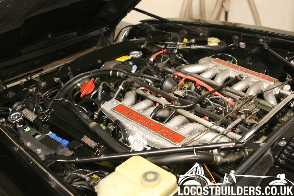
Nice bit of boxing in then and produce something like this ?

Stays flat under the bonnet, a v12 Jag has nice progression when driven and uses MAP (1/2" link pipe off the ends which feed the sensor and
balance the banks so no need to bring it altogether for a single MAF box.
Regards Mark
|
|
|
Ivan
|
| posted on 26/6/12 at 04:31 PM |

|
|
quote:
Originally posted by mark chandler
Nice bit of boxing in then and produce something like this ?

Stays flat under the bonnet, a v12 Jag has nice progression when driven and uses MAP (1/2" link pipe off the ends which feed the sensor and
balance the banks so no need to bring it altogether for a single MAF box.
Regards Mark
I agree - a balance pipe is an essential part of the plenum design.
|
|
|


