itsu-san
|
| posted on 16/9/10 at 07:37 AM |

|
|
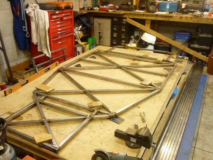
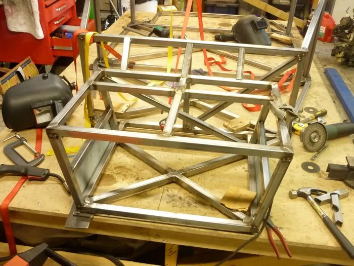
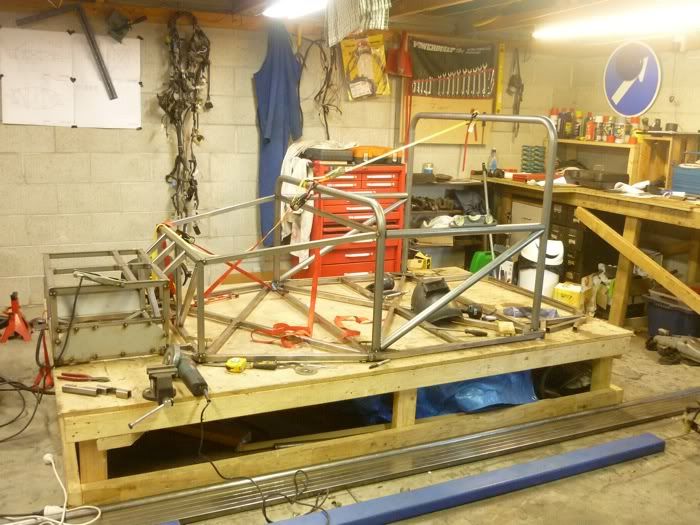
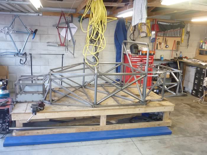
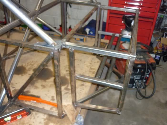
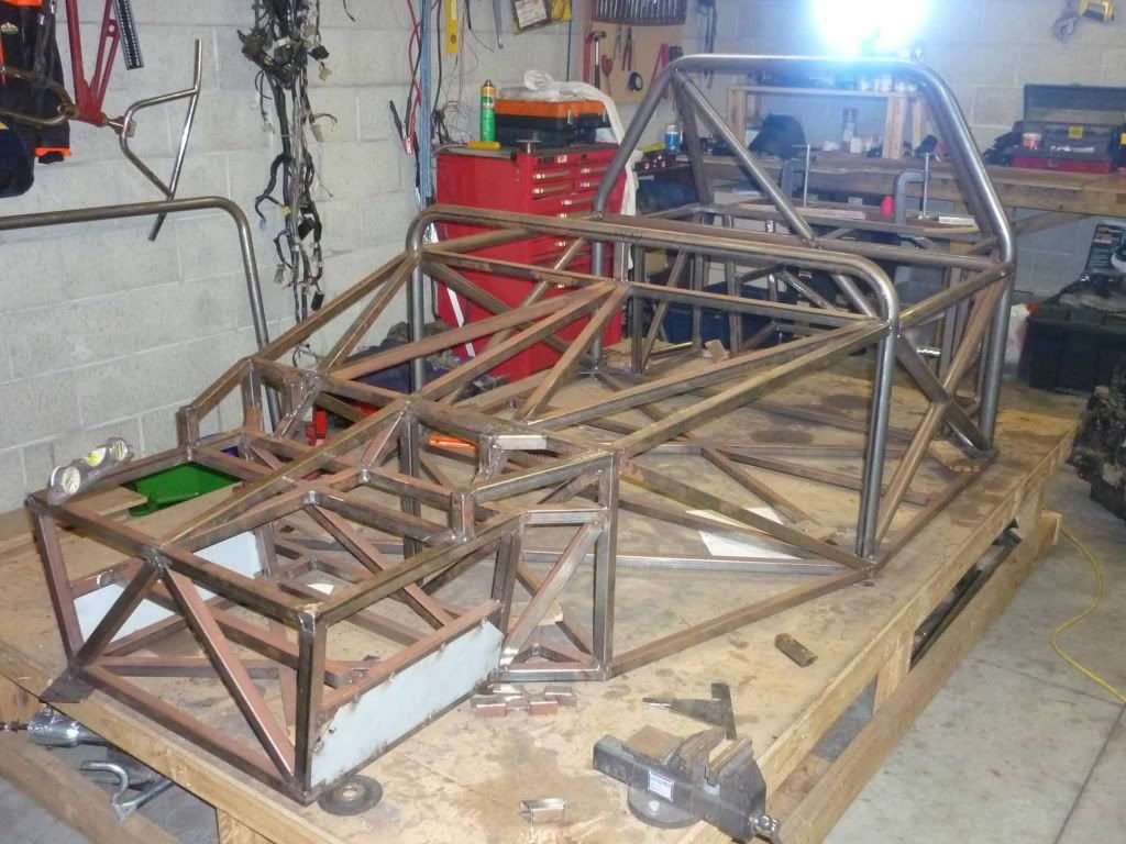
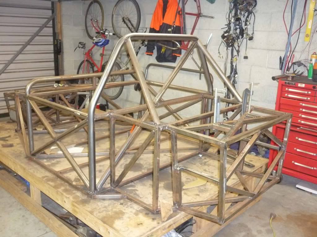
Hi guys heres the evidence that this thing is actually getting built.
Chassis base welded and clamped to the build table. Square and level to within cuoee
Flat
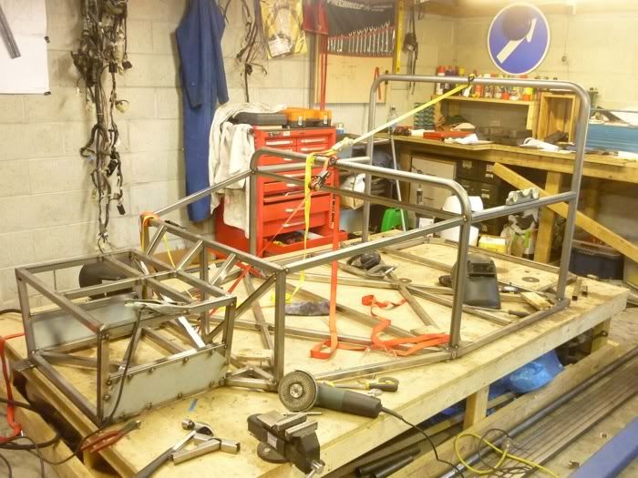
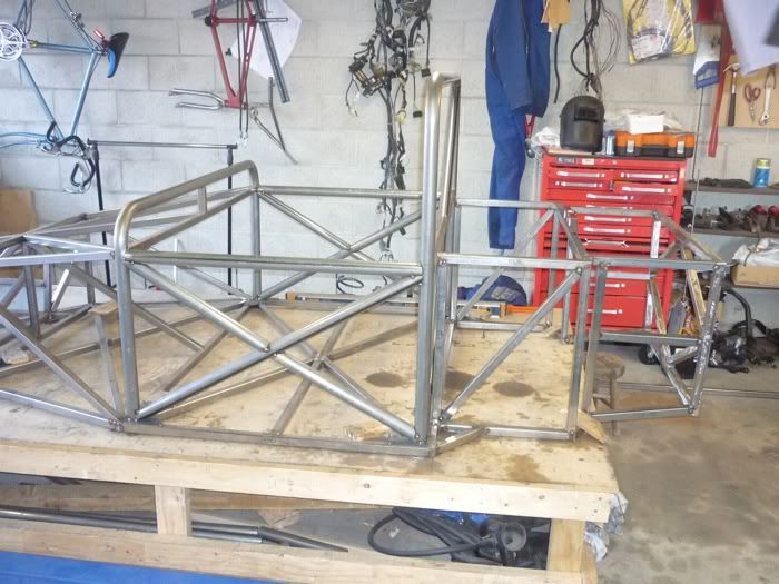
Coming together
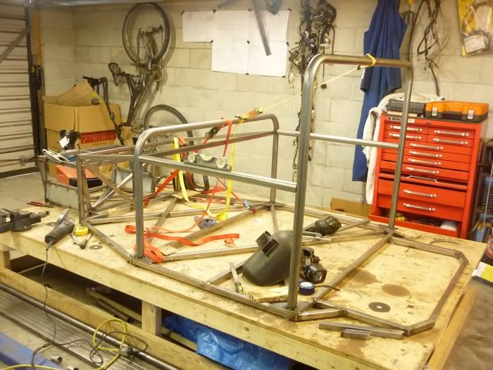
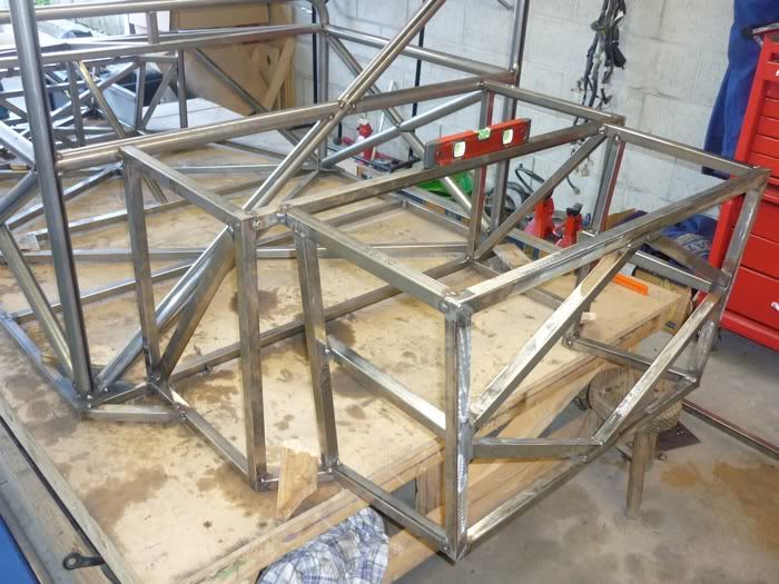
Front Subframe
3d
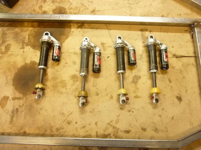
Shocks
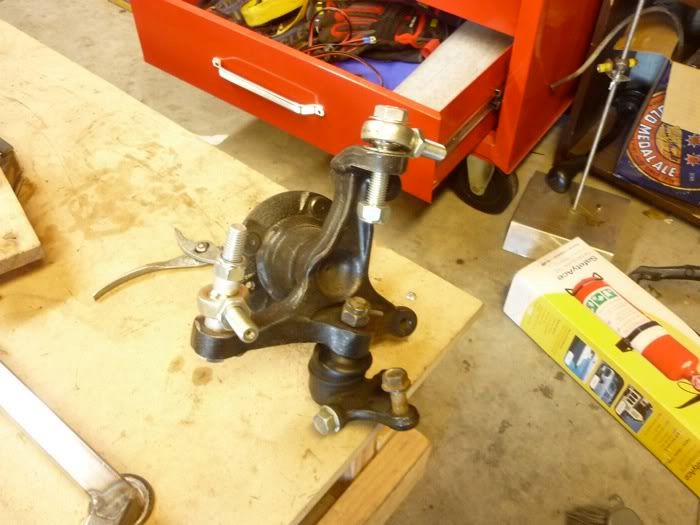
Front Upright
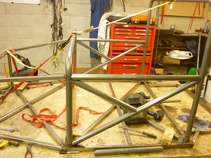
Roll cage
Rollcage side bars
|
|
|
|
|
Ivan
|
| posted on 16/9/10 at 02:33 PM |
|
|
Will watch the build with interest.
|
|
|
MakeEverything
|
| posted on 19/9/10 at 05:26 PM |
|
|
Looks fantastic.
Should the side cross members go all the way through? Frontal impact might see the car fold in half otherwise?
Kindest Regards,
Richard.
...You can make it foolProof, but youll never make it Idiot Proof!...
|
|
|
MakeEverything
|
| posted on 19/9/10 at 05:27 PM |
|
|
D'oh, just seen the other bits lying on the table! Sorted.
Kindest Regards,
Richard.
...You can make it foolProof, but youll never make it Idiot Proof!...
|
|
|
itsu-san
|
| posted on 20/9/10 at 11:11 AM |
|
|
Thanks! All the side bars are in now ill put pics up soon.
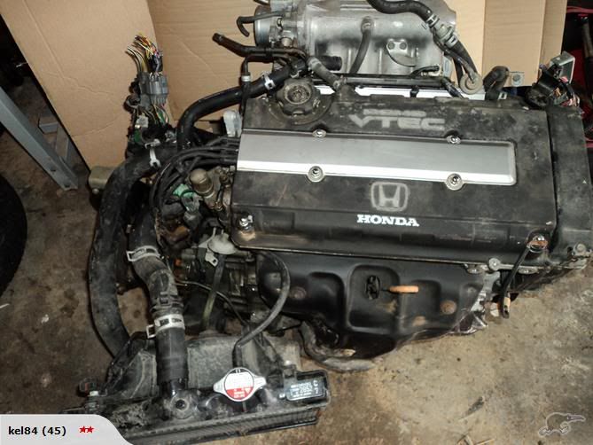
One of the opportunities you just can't pass up. 160hp Engine and gear box + drive shafts + etc for $350
What ya gunna do? 8-)
[Edited on 20/9/10 by itsu-san]
|
|
|
MakeEverything
|
| posted on 20/9/10 at 03:01 PM |
|
|
quote:
Originally posted by itsu-san
What ya gunna do? 8-)
[Edited on 20/9/10 by itsu-san]
....Turbo it!! 
Kindest Regards,
Richard.
...You can make it foolProof, but youll never make it Idiot Proof!...
|
|
|
itsu-san
|
| posted on 30/10/10 at 05:39 AM |
|
|
Hi All,
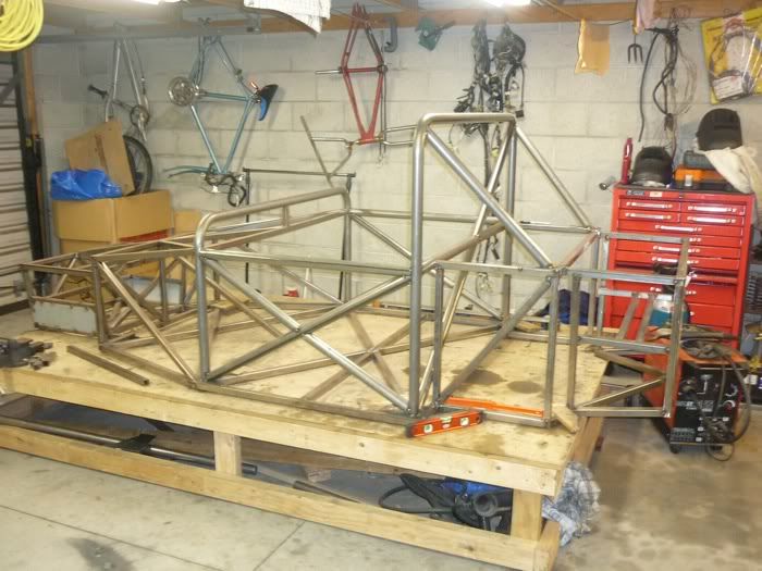
The chassis is just about ready for final welding. A handful of tubes to go in the rear sub-frame and its done.
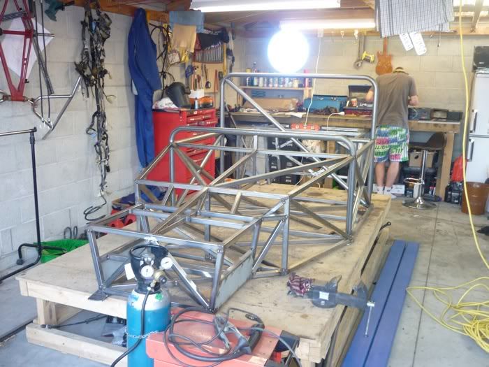
Exams are over on the 11th so expect to see a lot more progress in the near future
Cheers
Grant
[Edited on 30/10/10 by itsu-san]
|
|
|
MakeEverything
|
| posted on 30/10/10 at 11:27 AM |
|
|
Looks awesome, well done.
Cant wait to see it on wheels.
Kindest Regards,
Richard.
...You can make it foolProof, but youll never make it Idiot Proof!...
|
|
|
Gakes
|
| posted on 2/11/10 at 09:19 AM |
|
|
looking good dude. looking forward to the updates
 
Description
|
|
|
renrut
|
| posted on 11/11/10 at 01:37 PM |
|
|
Think you might have missed a trick with designing the rear suspension.
I've done a similar build with a small fiat. I copied the front suspension pick up points from the front chassis and used them as the basis for
building the rear. I even used a steering rack for the rear toe and kept the track width the same. Only thing that was a pain was making some adaptors
up to mount some handbrake'd calipers on the front hub carriers but thats 2 laser cut plates compared to a lot of possible suspension woes.
Looks good, I'm immensely jealous of the working space!
Why are all the fun things in life expensive!
|
|
|
kb58
|
| posted on 12/11/10 at 02:45 AM |
|
|
quote:
Originally posted by renrut
Think you might have missed a trick with designing the rear suspension.
I've done a similar build with a small fiat. I copied the front suspension pick up points from the front chassis and used them as the basis for
building the rear. I even used a steering rack for the rear toe and kept the track width the same...
Assuming that the same uprights are used at all four corners, it means the front and rear RC is in the same place, unless the suspension arms
werevery carefully designed to somehow put both front and rear RCS where they're wanted.
Mid-engine Locost - http://www.midlana.com
And the book - http://www.lulu.com/shop/kurt-bilinski/midlana/paperback/product-21330662.html
Kimini - a tube-frame, carbon shell, Honda Prelude VTEC mid-engine Mini: http://www.kimini.com
And its book -
http://www.lulu.com/shop/kurt-bilinski/kimini-how-to-design-and-build-a-mid-engine-sports-car-from-scratch/paperback/product-4858803.html
|
|
|
itsu-san
|
| posted on 17/11/10 at 07:10 AM |
|
|
|
|
|
Ratman
|
| posted on 12/2/11 at 04:27 AM |
|
|
Looking very good Itsu. One thing to bear in mind is that the triangulation makes for a stiff chassis, but you only get the full benefit of it if the
suspension attachment points (including bell cranks and shock mounts) are at the triangulation nodes. But this is generally rather hard to get
perfect and some compromise generally results. I'm guessing that the rear-most box on your chassis is there to take the rear suspension. So, is
it possible to make the corners of the box, the same points as the inboard ends of the A arms? Or would the chassis members then interfere with
internal organs? These aren't questions.. I'm just wondering aloud. How's progress been over the summer?
|
|
|
itsu-san
|
| posted on 13/2/11 at 09:33 AM |
|
|
Hi Ratman,
I have been working 6 days a week all summer, inspite of this there has been lots of progress although mostly in theoretical understanding and design
work. Tumbling further down the rabbit hole so to speak.
The front suspension is almost ready for fabrication. Just awaiting final design of inboard mounts and then they will be laser cut.
Part of the reason for the slow physical progress has been due to time spent writing our own program to model the suspension geometry.
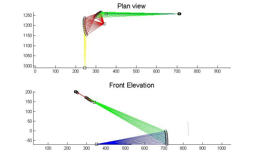
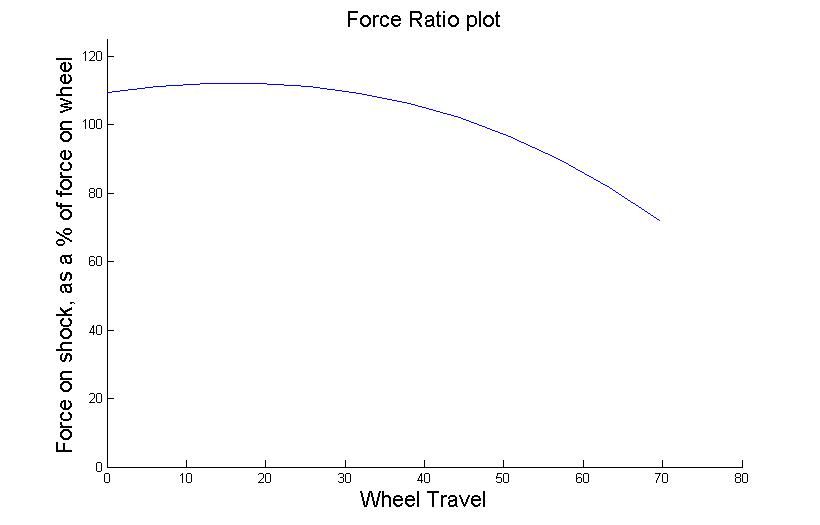
Rear suspension
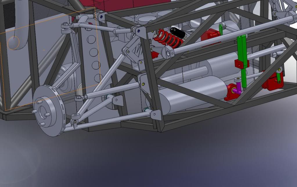
Still work to do here.
Building a shock dyno too
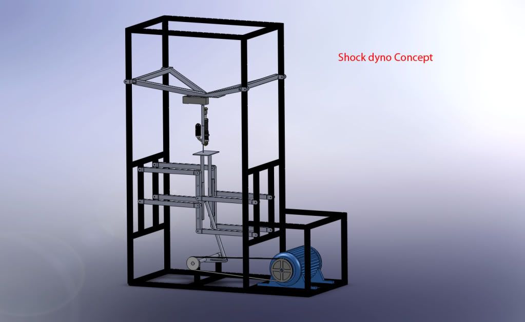
Thanks for the interest!
G
[Edited on 13/2/11 by itsu-san]
|
|
|
Ratman
|
| posted on 25/2/11 at 09:49 PM |
|
|
I hope you (and your project) are OK after the Earthquake. I have in my mind your garage full of liquification silt and everything in the workshop
strewn across the floor. Tell us it isn't so.
http://www.youtube.com/results?uploaded=w&search_query=christchurch+earthquake+footage&search_type=videos&suggested_categories=25&page
=2
|
|
|
itsu-san
|
| posted on 27/4/11 at 10:53 AM |
|
|
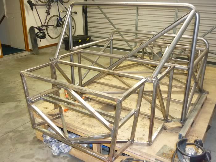
It's been awhile since the last update but im really happy with how the project is going. The suspension has been modelled, analysed, optimised
and designed in details down to the last nut and bolt! I decided to cut out the old 38mm OD roll bar and get a new roll bar bent up in 44mm OD. It
brings the car in line with the new NZ motorsport regulations and i think the new design looks a bit better aswell. Managed to get it in there without
disturbing the frame too much. Chassis has now got all the major tube members tack welded in place and is ready to be fully welded. I've got
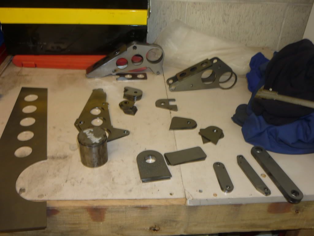
about 70 parts getting laser cut at autobend in the next week or so which will take the project a massive step foreward when they arrive. I've
been on the lathe for the last two days turning up spacers for the rod ends and various bit and pieces to help jig up the suspension plates onto the
chassis.
Front of the chassis
Rear of the chassis
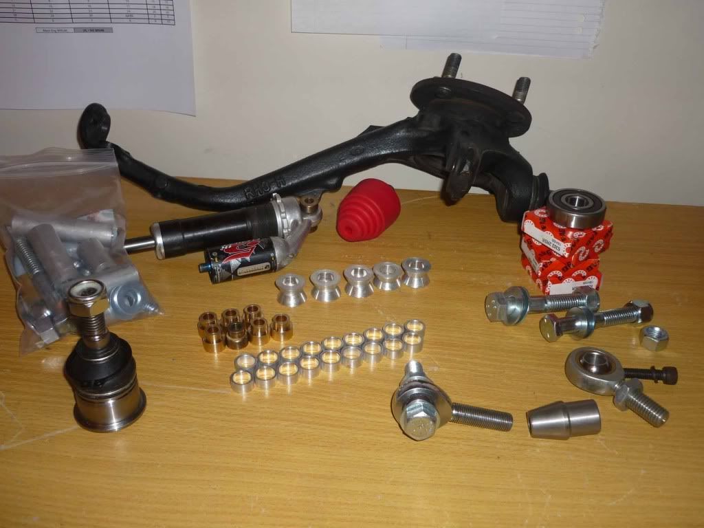
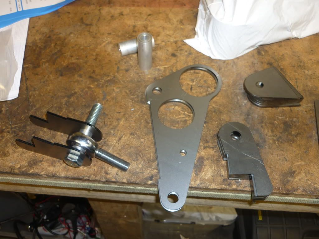
starting to aquire a few of the suspension parts
Cheers
Grant
|
|
|
Miks15
|
| posted on 27/4/11 at 11:58 AM |
|
|
Its looking good, completly missed this thread first time around but glad i spotted it now.
|
|
|
itsu-san
|
| posted on 28/4/11 at 04:24 AM |
|
|
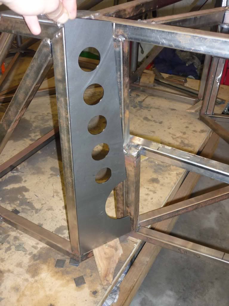
First laser cut parts arrived today the rear chassis plate! Fits nicely! 
|
|
|
HowardB
|
| posted on 28/4/11 at 06:48 AM |
|
|
looks great, I am really impressed....
keep up the pictures,.....
Howard
Fisher Fury was 2000 Zetec - now a 1600 (it Lives again and goes zoom)
|
|
|
Livio
|
| posted on 1/5/11 at 02:25 PM |
|
|
Those red boxes at the rear of the car are actators for the gear linkage?
Do you have any specific information about them? How are you going to control them?
How strong and robust are they?
|
|
|
v8kid
|
| posted on 1/5/11 at 02:56 PM |
|
|
And why are they mounted remotely?
You'd be surprised how quickly the sales people at B&Q try and assist you after ignoring you for the past 15 minutes when you try and start a
chainsaw
|
|
|
Doug68
|
| posted on 2/5/11 at 10:31 AM |
|
|
Hi Istu san,
Check out this blog post it might give you an idea for a simpler gear shifting mechanism.
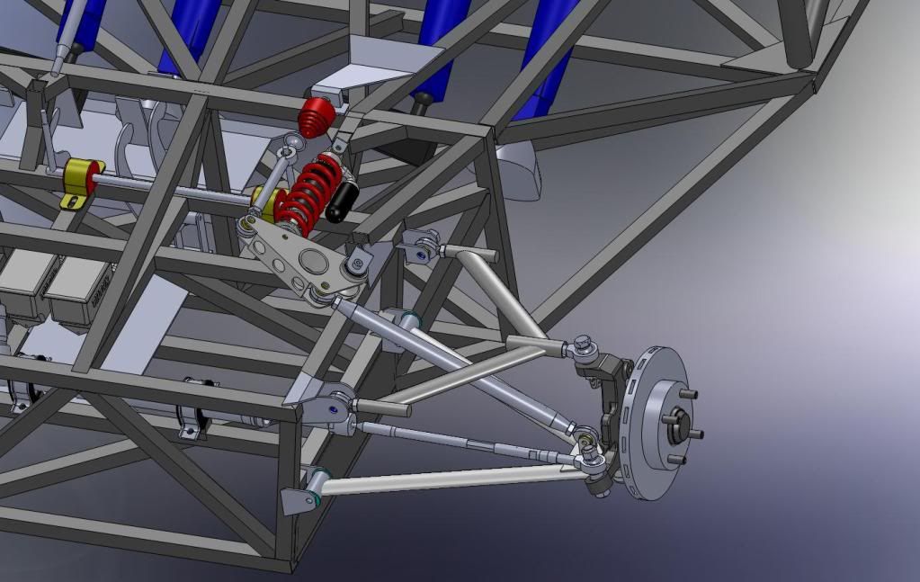
I realize it may well be a CAD work in progress, but the brackets on the wishbones that the push rods attach to, look to weedy to me. Also the top
rear A looks like it might run out of motion on the bearing before bottoming out. Beware of that sort of thing as if it happens the results could be
catastrophic. If its close you my find yourself running out of camber adjustment.
This top outer bearing doesn't need to be a threaded unit as the two inners should give you the adjustment you need if you can change to a press
in type and cant the end fixture to be square at 1/2 travel that might be a better solution.
Keep up the good work!
Edit:
looking at the pictures it struck me the tube for the chassis is bright.
Seeing as NZ doesn't make any steel tube, that means its imported, so do you know what it is and where its from?
I'm afraid it might be Australian as the bright tube from Australia is generally GR250, used for furniture as its nice and easy to bend and not
what I'd use for a chassis.
The blue painted material is what's normally in Locost construction in Aus as its GR350 (and printed on the side of tube as such).
Hope I've not just ruined you day. 
[Edited on 2/5/11 by Doug68]
[Edited on 2/5/11 by Doug68]
[Edited on 2/5/11 by Doug68]
Doug. 1TG
Sports Car Builders WA
|
|
|
britishtrident
|
| posted on 2/5/11 at 11:05 AM |
|
|
Sweet --- "looks right is right".
In the words of Wayne and Garth "We are not worthy ! "
|
|
|
itsu-san
|
| posted on 3/5/11 at 03:27 AM |
|
|

|
|
|
itsu-san
|
| posted on 3/5/11 at 03:39 AM |
|
|
Hi Doug,
I really appreciate you taking the time to eye over my design. You are correct old cad model! Both the rod end motion range and push rod mount have
been changed. Ill post latest design when i get home.
Ive changed the adjustment set up for the A-arm so that camber can be adjusted without having to remove the arm, ill post a pic of this too.
The steel for the chassis is 25.4x25.4x16 As1163 - C350/450 ie 350 mpa yield same as what you're using.
Cheers
Grant
|
|
|