Knumbskull
|
 posted on 11/7/24 at 10:08 AM posted on 11/7/24 at 10:08 AM |

|
|
R1 4XV wiring help please ,No spark
Hi All.
Just joined and really hope someone can help please.
Just got round to starting on a project which my son got with an R1 4XV engine in (probably 1998).
(Wiring been hacked and mess, etc,so need to work through hopefully eliminating problems.
Just want to know I can achieve a spark and go from there.
I am a complete novice and not familiar with wiring,etc at all so please bear with me (hence the username)
I found a post onthe site posted on 3/9/06 at 04:07 PM which looked absolutely ideal for what I require to help
me as it had a good diagram but no matter what I do I cannot make it clear enough to make out wire colours etc.
Any help regarding getting a clearer view of this and also my no spark problem would be fantastic and greatly appreciated please ?
|
|
|
|
|
gremlin1234
|
| posted on 11/7/24 at 11:38 AM |
|
|
welcome
could you please add a link to the post that you refer too.
but a quick search found a different thread that might help you
https://www.locostbuilders.co.uk/viewthread.php?tid=212769
|
|
|
Knumbskull
|
| posted on 11/7/24 at 01:04 PM |
|
|
Hi, thank you for your help.
That's a brilliant diagram, the link to what I found is below:
https://www.locostbuilders.co.uk/photos.php?action=showphoto&photo=a423831-r1.GIF
If I can get one as clear for the 1998 4XV model it will hopefully start me slowly on my way to understanding a bit more clearly as I'm
totally rubbish with wiring but have no other choice than to try and muddle through. All help very appreciated, thank you.
|
|
|
gremlin1234
|
| posted on 11/7/24 at 04:26 PM |
|
|
I did a little magic, here is the original gif file,
and following that a jpg version. (sorry its a very big picture)
I hope this means you can read it
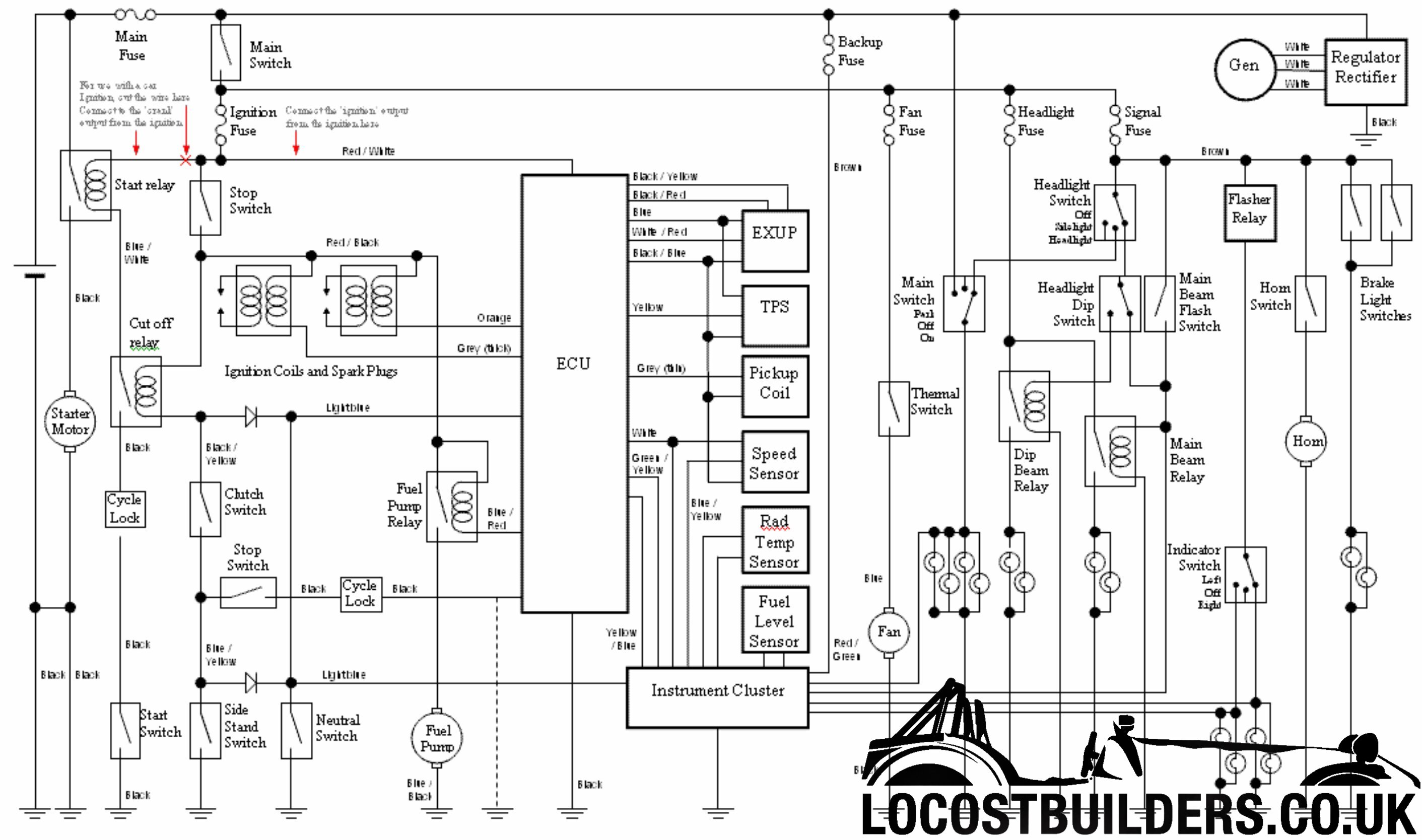
r1 diagram from gif now jpg
|
|
|
gremlin1234
|
| posted on 11/7/24 at 04:34 PM |
|
|
if there are any bits you can't read in the above images, then ask, I can read all the colour codes etc
the two annotations say
for use with a car Ignition cut the wire here, Connect to 'crank' output from ignition
and
Connect the 'ignition' output from ignition here
|
|
|
Knumbskull
|
| posted on 11/7/24 at 05:22 PM |
|
|
Hi,
You're an absolute star, thanks so much, this will be an unbelievable help.
Unfortunately the whole thing is a wiring mess and is going to be an uphill struggle for a complete novice like me without a clue of wiring but this
will really help to steer me in the right direction hopefully. Don't suppose you could explain what the cycle-lock is and what it looks like so I
know please? Once again so grateful for your help.
|
|
|
gremlin1234
|
| posted on 12/7/24 at 11:21 AM |
|
|
quote:
Originally posted by KnumbskullDon't suppose you could explain what the cycle-lock is and what it looks like so I know please?
see
https://www.locostbuilders.co.uk/forum/9/viewthread.php?tid=31026
|
|
|
Knumbskull
|
| posted on 12/7/24 at 12:01 PM |
|
|
Hi
Thanks, even with your brilliant help and diagram I think my understanding is going to struggle, if you could pm me I can email you a photo of what
I'm up against, wires chopped, etc, wires which I don't know if or where they should be connected, sorry
|
|
|
Knumbskull
|
| posted on 12/7/24 at 06:06 PM |
|
|
quote:
Originally posted by gremlin1234
quote:
Originally posted by KnumbskullDon't suppose you could explain what the cycle-lock is and what it looks like so I know please?
see
https://www.locostbuilders.co.uk/forum/9/viewthread.php?tid=31026
.
So grateful for your help. Spent several hours vacantly looking at the wiring.Have took photos, then removed the wiring and took photo of complete
harness (total mess, unknown wires, to me anyway, etc. If I can somehow get these photos to you that would be brilliant, as I'd really
appreciate any guidance in getting the harness in to a state for purpose of achieving a spark. (just need a simple wiring system to run engine, not
concerned about lights, etc) Will totally understand if you think I'm a lost cause. Sorry for being a pain.
|
|
|
JMW
|
| posted on 14/7/24 at 09:56 AM |
|
|
I know very little about bike wiring so ignore this if it's rubbish, but isn't there a thing with some bike wiring harnesses that they need
to simulate the side stand being 'up'? Nothing to happen unless it's 'up'.
So that the rider can't set off with it still down by mistake?
The diagram makes no mention of this so maybe this isn't relevant, or maybe it's what the cycle lock is? Probably not though.
As I said, please ignore if irrelevant.
|
|
|
Knumbskull
|
| posted on 14/7/24 at 10:28 AM |
|
|
quote:
Originally posted by JMW
I know very little about bike wiring so ignore this if it's rubbish, but isn't there a thing with some bike wiring harnesses that they need
to simulate the side stand being 'up'? Nothing to happen unless it's 'up'.
So that the rider can't set off with it still down by mistake?
The diagram makes no mention of this so maybe this isn't relevant, or maybe it's what the cycle lock is? Probably not though.
As I said, please ignore if irrelevant. [/quote
]
Hi,
Thanks for your input, as any help I can get is truly appreciated. Yes you are correct about the sidestand, same as clutch switch. On the diagram
you'll see its at the bottom in between start switch and neutral switch. It's awful trying to rectify stuff when you not feeling competent
enough. Once again, thank you.
|
|
|
JMW
|
| posted on 14/7/24 at 11:00 AM |
|
|
Ah thanks, Specsavers beckons for me.
Also, I think you need to replace the switch with a resistor for some reason, rather than just completing the circuit.
|
|
|
adithorp
|
| posted on 14/7/24 at 11:01 AM |
|
|
It's daunting but you just need to work through what you've got.
Work methodically, and identify each wire/sensor/relay. Label them all as you go. Masking tape and write on that will do. Get a big print of the
wiring diagram (a3) and make notes on that, ticking off things as you identify them.
Once you've done that you'll a) understand how it works better and b) what's been done/not done/ removed.
Things like is the car using the bike loom to run everything or just the motor. I have the bike loom just running the engine and a separate loom for
lighting etc. If yours has been done the same you'll find lots of wires cut/removed that would have gone to lights.
Work out if you have the cycle lock. That's the immobiliser. The wiring diagram is deliberately vague on that for security. It's switched
via a transponder chip in the key and pickup coil around the ignition lock. It depends on the market the bike was sold in (at least on later engines)
so might not be present.
"A witty saying proves nothing" Voltaire
http://jpsc.org.uk/forum/
|
|
|
adithorp
|
| posted on 14/7/24 at 11:11 AM |
|
|
quote:
Originally posted by JMW
Ah thanks, Specsavers beckons for me.
Also, I think you need to replace the switch with a resistor for some reason, rather than just completing the circuit.
Some sessions require a resistor (or more) to prevent a fauly showing in the bike dash (if your using it) but clutch/side-stand/switches can just be
connected to earth. You need to need to earth the neutral for the start logic circuit while keeping the connection between ecu/dash and switch for the
neutral light to work.
"A witty saying proves nothing" Voltaire
http://jpsc.org.uk/forum/
|
|
|
Knumbskull
|
| posted on 14/7/24 at 11:41 AM |
|
|
quote:
Originally posted by adithorp
It's daunting but you just need to work through what you've got.
Work methodically, and identify each wire/sensor/relay. Label them all as you go. Masking tape and write on that will do. Get a big print of the
wiring diagram (a3) and make notes on that, ticking off things as you identify them.
Once you've done that you'll a) understand how it works better and b) what's been done/not done/ removed.
Things like is the car using the bike loom to run everything or just the motor. I have the bike loom just running the engine and a separate loom for
lighting etc. If yours has been done the same you'll find lots of wires cut/removed that would have gone to lights.
Work out if you have the cycle lock. That's the immobiliser. The wiring diagram is deliberately vague on that for security. It's switched
via a transponder chip in the key and pickup coil around the ignition lock. It depends on the market the bike was sold in (at least on later engines)
so might not be present.
Thanks for taking the time getting back with such a good insight. Embarrassed on how little I understand and can't grasp wiring so please bear
with me. I think I need to take photos of what the loom is like now,then strip back and trace everything and take more photos. I can't work out
how to add photos on here so that was reason I requested a private message so I could hopefully email photos to someone more knowledgeable. Just want
a stand alone ignition system for now to see if a spark can be achieved with available wiring as no clocks, etc and go from there. Cheers for your
help 👍
|
|
|
Knumbskull
|
| posted on 16/7/24 at 06:10 PM |
|
|
Managed to get a bit of time, so have removed the wiring, slightly stripped it back, can anyone
advise on how I can add photo on here please? Just thought it would be good to post photo 🤔before I
venture any further with it (feel apprehensive)
|
|
|
Mr Whippy
|
| posted on 16/7/24 at 08:36 PM |
|
|
Go to your photo archive at the top left of the screen, select a reasonable sized jpg file and upload it, there are two types of links given when you
go into that photo's screen. Simply paste one of those links in to the post.
Top link is a pop up expanding one, bottom is full size... do check as modern camera files are HUGE and it's not much fun scrolling for hours
just to reach the other side of the screen.
Don't name files like Pic1, car2, img1234 etc as the forum gets confused and often will show someone else's picture instead  , pick
something like some random words. , pick
something like some random words.
[Edited on 16/7/24 by Mr Whippy]
Fame is when your old car is plastered all over the internet
|
|
|
Knumbskull
|
| posted on 16/7/24 at 09:41 PM |
|
|
Thank's, I will give it a go in the morning, cheers for your help.
|
|
|
Knumbskull
|
| posted on 17/7/24 at 06:01 AM |
|
|
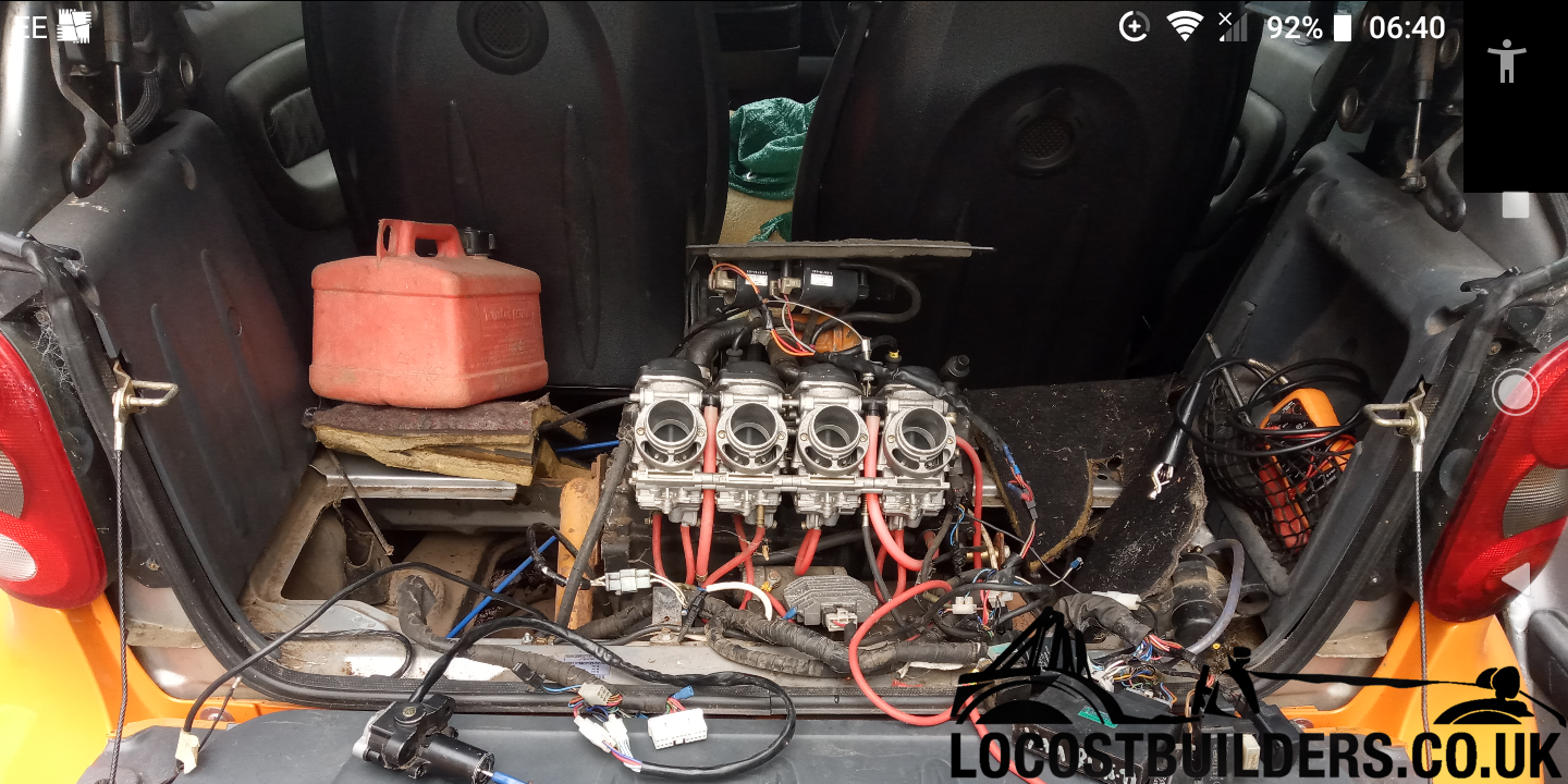
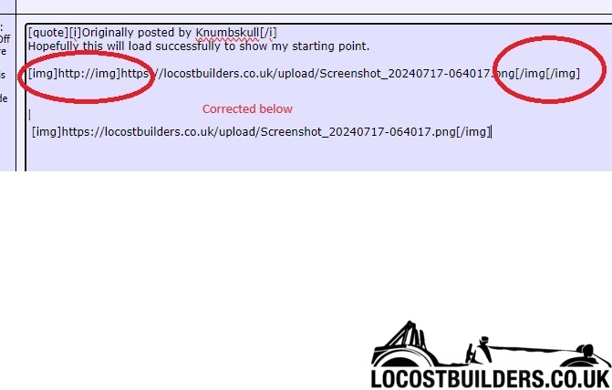
Hopefully this will load successfully to show my starting point.
[img]http://img]https://locostbuilders.co.uk/upload/Screenshot_20240717-064017.png[/img[/img]
Sorry if it doesn't as I'm about as good at this as I am with wiring!!!!
|
|
|
Knumbskull
|
| posted on 17/7/24 at 06:05 AM |
|
|
Looks like I'm not too good at this either.
Wiring I've removed and partially stripped
is in my photo archive, any pointers really appreciated.
|
|
|
Mr Whippy
|
| posted on 17/7/24 at 06:30 AM |
|
|
quote:
Originally posted by Knumbskull
Hopefully this will load successfully to show my starting point.
[img]http://img]https://locostbuilders.co.uk/upload/Screenshot_20240717-064017.png[/img[/img]
Fame is when your old car is plastered all over the internet
|
|
|
Mr Whippy
|
| posted on 17/7/24 at 06:38 AM |
|
|
No worries, just match the format below -
Fame is when your old car is plastered all over the internet
|
|
|
Knumbskull
|
| posted on 17/7/24 at 07:07 AM |
|
|
Thank's for doing that for me, I will try to do the other photo.
|
|
|
Knumbskull
|
| posted on 17/7/24 at 07:13 AM |
|
|
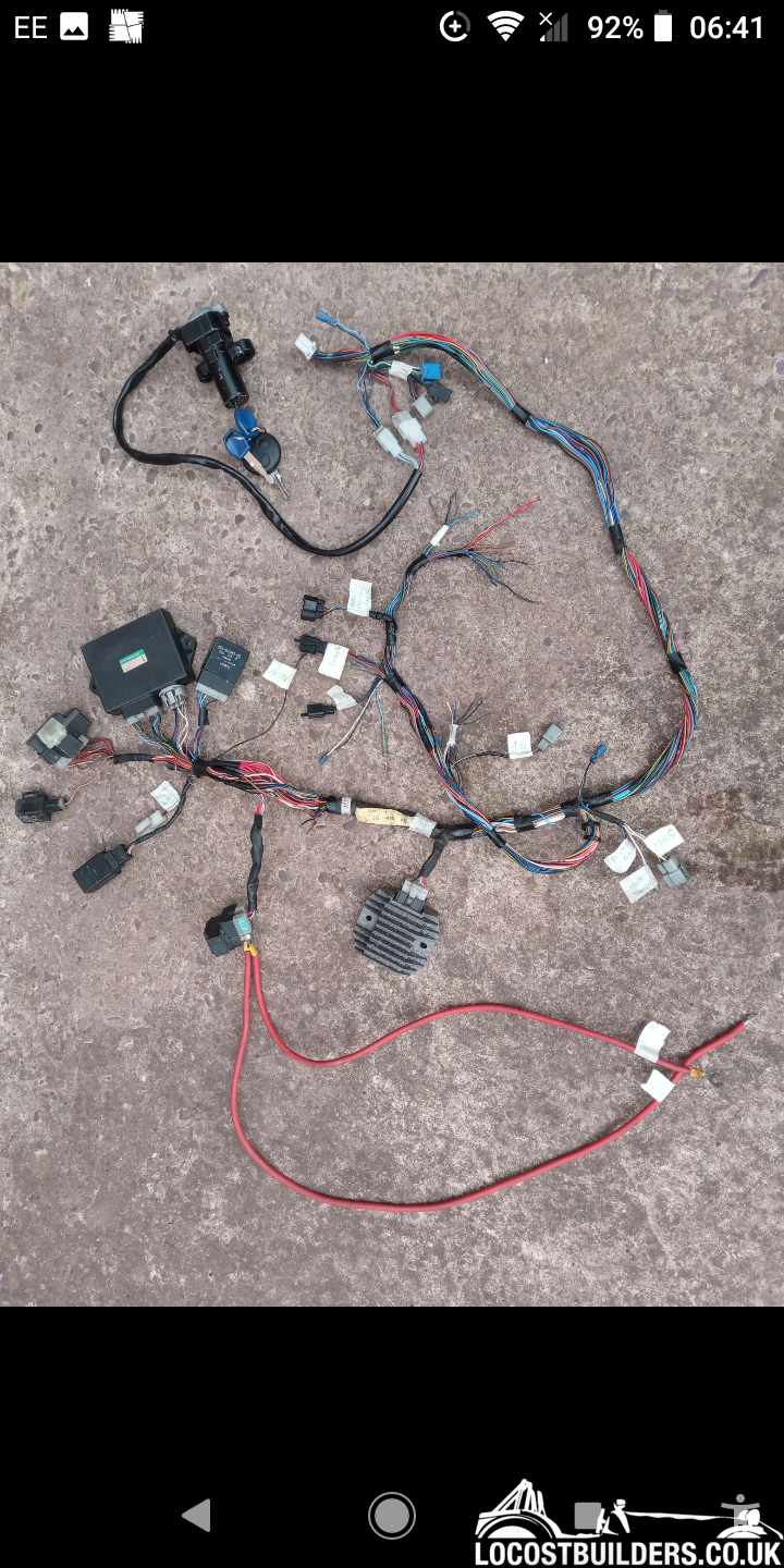
Hope the image of removed and partially stripped wiring is now showing, any pointers or advice appreciated
|
|
|
Knumbskull
|
| posted on 17/7/24 at 05:33 PM |
|
|
As you'll see its been quite a time trying to sort through.
Would be so grateful for any help and guidance with what my concerns are please.
1/White 2 spade plug (EARTH CLAMP ON ENGINE) runs to black female 2 socket (ENGINE EARTH CLAMP) this socket
does not attach to anything???
2/Red/black wire ( STARTER RELAY (10) ) and Red/white wire (CDI (17) ) were twisted together, is this correct?
3/Black wire (EARTH?) from cdi 6 pin plug doesn't seem to go anywhere?
4/Black wire (EARTH?) from starter relay doesn't go to anything?
5/Blue/yellow (CLUTCH SWITCH (39) ) goes to 4 pin ignition plug and Black/yellow (CLUTCH SWITCH (39) ) goes to 6 pin blue socket? Shouldn't the 2
be joined???
All seems a total mess, really hope someone with expertise can help guide me as what should go where, etc to hopefully achieve a spark please.Will
attach photos in next post. Thanks again for previous help.
|
|
|