
Rescued attachment P3040003sm.JPG
I want to build a scale model of my chassis. Maybe 1/20 scale, so no welding. I'm looking for suggestions on materials and techniques som of you may have used to build yours.
Quick and dirty for a visual--poster board
my rough model took just over an hour to do.
http://locostbuilders.co.uk/viewthread.php?tid=20059&page=2
dale
Good Idea for the body. Could be tough for me though because I've got compound curves.
Right now, I'm really interested in just the space frame chassis.
Balsa wood strips
Yup, balsa wood. Go to your local hobby supplier and buy some balsa blocks, sheet, and strips, some super glue and a knife.
Many years ago I made some models of spaceframe chassis out of brass wire from a model shop. the wires were cut to size then soldered with a soldering
iron. Welding or brazing rods would be cheaper. This method is good for seeing the weak points in a design - a good design will be stiff when you
twist it. A poor design will flex. The seven style chassis here was based on pictures of a Westfield chassis I saw in a magazine. I'm afraid it
flexes more thatn other designs.
Rescued attachment P3040003sm.JPG
This mid-engine chassis is much stiffer - but benefits from impractical triangulation in the front and rear sections.

Rescued attachment P3040004sm.JPG
That's just what I needed. I need to build a model with curved chassis members. I was wondering how I'd bend balsa sticks! 
Brass would be perfect!
A couple of different points:
Jermyn - I'll agree with kb58 and others; balsa is cheap and easy to work with. I'd go bigger than 1:20 scale however. At that size 25mm
(1" ) tubes aren't much bigger than 1mm (50 thou) ! Not easy to work with and VERY fragile. I've built some models at 1:10 which is
very easy to do scale calculations on (at least in metric  ). I've also done a few at 1:6 because I have a 1:6 artists dummy that I can then
use for scale comparison and reality checks.
). I've also done a few at 1:6 because I have a 1:6 artists dummy that I can then
use for scale comparison and reality checks.
timsta - curved chassis tubes are EVIL! They might look cute on the Ariel Atom but they're weaker than using straight tubes of the same size
(which is why the Atom side rails are quite large diameter). Colin Chapman used to describe the curved chassis tubes on the Cooper formula cars as
"pre-failed"! Proceed with caution 
JonBowden - very nice work!
Dominic
[Edited on 3/2/2005 by TheGecko]
quote:
timsta - curved chassis tubes are EVIL! They might look cute on the Ariel Atom but they're weaker than using straight tubes of the same size (which is why the Atom side rails are quite large diameter). Colin Chapman used to describe the curved chassis tubes on the Cooper formula cars as "pre-failed"! Proceed with caution
quote:
when you're trying to create a Atom replica you really don't have too much choice!
Jon,
Your model construction is excellent. It is exactly what I want to simulate. Couple questions...
1. Were the brass rods solid or hollow?
2. What sort of amperage/power soldering iron did it take? I have a smaller one I use for electrical work and a trigger-gun type one. I cannot recall
the amperage off hand. But it seems that it may take a while to get the rod hot enough with the type I have.
3. Was there a specific solder you used? Lead mix? electrical type? etc...
4. Did you have to use flux?
1. solid, about 18 swg.
2. I used an 18W small electrical iron, but more power would have helped.
3. Ordinary 22swg tin and lead multicore solder - from any electronic component shop.
4. No flux was added (the solder above has flux in it). Just clean the brass rod ends.
Note, there is some skill needed to solder well but it is not hard to learn (easier than welding) - just practice first
Jon
Jermyn
This might give you some inspiration for a taller and wider seven.
This is a Kougar Sports (http://www.kougar-cars.com). It isn't really a locost - based around Jag bits.
Jon

Rescued attachment 22.jpg
Coathangers and steel brake line soldered together with silver solder, flux and a refillable butane blowtorch works very well.
You can actually get micro bore brass and steel tube from model shops. Very expensive though unless you can find their source and buy sensible
lengths.

Rescued attachment scale_model01.jpg
Thanks to everyone who gave me some ideas. I went to the hobby store yesterday and picked up some brass 2mm RHS. They sold it in 1ft lengths. It was
about $1 a foot. I bought 10ft. I will probably have to go back and get more.
They actually had all different kinds of the stuff. Hollow, solid, round, square, L-shaped, C-shaped, and plates. Aluminum, brass, copper and
steel.

Rescued attachment 114_1472.JPG
hmmm, sure i once heard that a solid 2.5mm balsa strip has similar properties to 25mm 1.6mm steel tube. If i'm not wrong i'd reconmend that.
JonBowden
Nice mid engined chassis.
I have considered something similar but as a full width body is out of the question in my cramped garage I'll probably be aiming for something
more 7 shaped.
I notice the double Y brace at the rear. Very good. Have you a background in structural design? Why was the Middy triangulation impractical? I'm
getting involved in a real racing car project and would be very interested to know why you rejected that chassis design!
If you check my posts regarding finite element analysis of the Locost chassis I suggest a double Y brace for the Locost engine bay.
cymtriks
Thanks - its a design I made about twenty years ago to help avoid studying for computer science exams.
I have always liked machines and structures.
The double Y brace was just the only way I could make space for the engine.
The design relies heavily on the full triangulation of the 'boxes' at the front and rear.
The problems are :
1. the engine and gearbox have to go through the front triangulation of the rear box.
2. the drive shafts must pass through the side triangulations of the rear box.
The first problem could be partially solved by using a 'Lotus bulkhead' as on Lotus 18, 23 and probably many others.
I'm sure the second could also be overcome
I haven't rejected the design but after about twenty years, I still don't have space to build it.
I have read your posts with great interest. You inspired me to get a copy of Grape but I still haven't figured out how to work it.
Jon
I made two 1:8 scale models; one "Book" version and the one pictured below (+3+2).
I used 1/8 x 1/8 "stick" balsa for the 1 x 1 RHS, 3/32 x 3/32 for the 3/4 x 3/4 RHS tubes. The roll bar is modeled using 3/16 dia alum
(solid), the boot's top and bottom tubes were modeled using 3/32 dia alum (solid). All materials were purchased from a hobby shop.
I drew a complete set of plans for each tube and major assy in 1:8 scale, then cut/bent/and built the chassis on top of the plans (using traditional
"stick & tissue" model airplane methods). Super Glue was used to bond the balsa and JB Weld was used to bond the roll bar tubes
together.
Note that I took the center section out of tube Q to provide more room to move the 3.4L 60 deg Chevy V6 eng aft (better wt distribution and additional
distributor clearance)...raised the boot's top tube 1" (w/a 1x1 rhs "spacer" that also stiffens the shock attach plate's
outside edge), this is to provide ~1.75" of body panel showing above the rear wings. The +2" of chassis height is from tube B2 fwd. The
extra 2" provides more room for the V6. A side benefit of keeping the height at the book level aft of B2 is that I can slope tubes N1/N2 down
achieving a more traditional Lotus 7 look!
[Edited on 10/2/05 by Pseudo7]
...here's the pic (I hope!)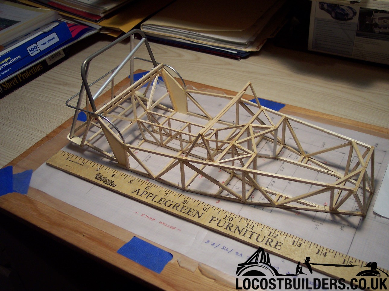
...another pic on the rear: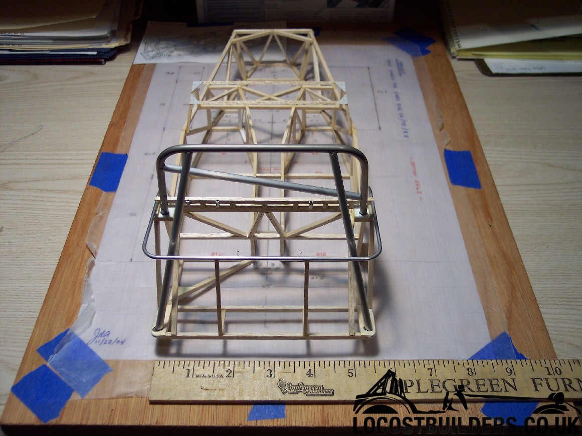
....and one more:
..ah, hell, one more!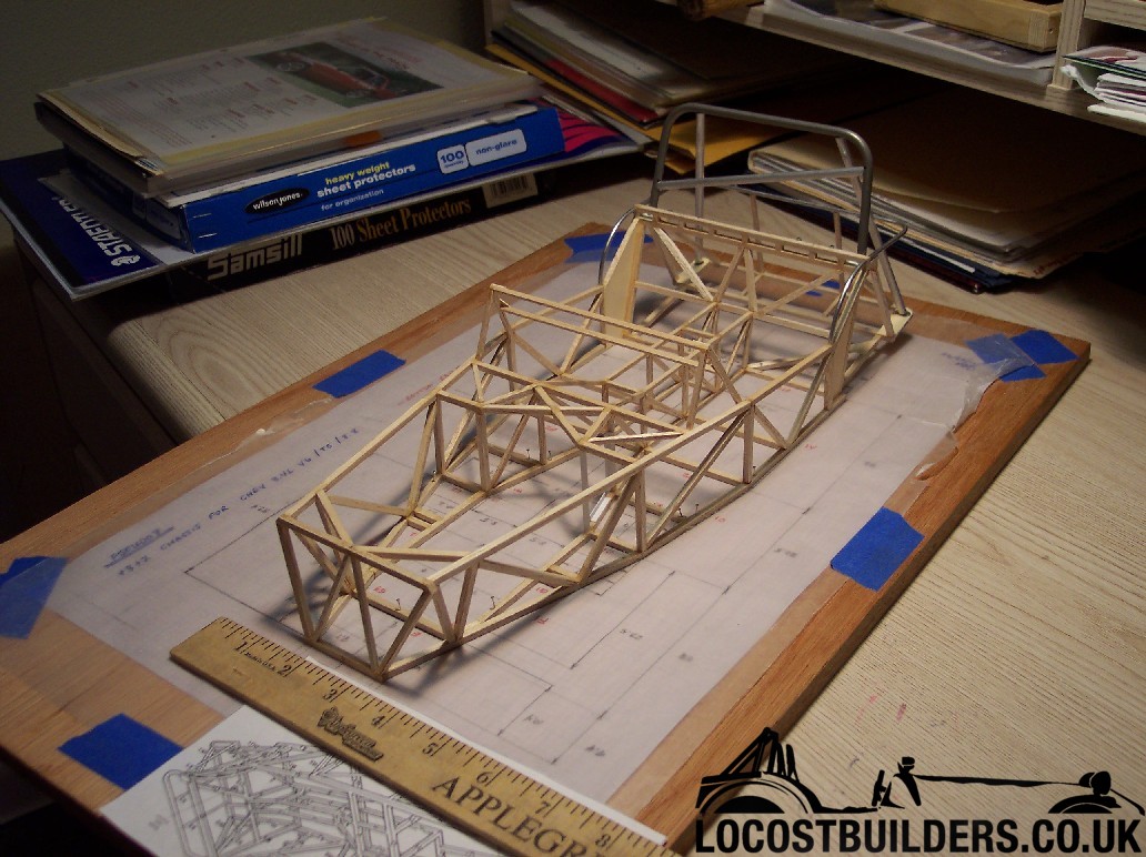
Have to throw in my .000002 cents here.
I think the brass and metal tubing is great for studying the layout of the tubes, but if you want to do some useful analysis of the rigidity of your
structure (without the benefit of really smart and well connected people in with access to FEA) you will want to use balsa. I believe Caroll Smith and
Alan Stanisforth both advocate the use of balsa models.
A few comments -
Pseudo_7 - that's a lovely piece of modelling - well done! I agree with Steve that you try to stick with one material if you hope to get any
sort of qualitative data from a model.
Jermyn & Dale - any chance you guys could make your avatars a little smaller. I'm limited to 1280x1024 at both home and work at present, so
your 320 pixel wide avatars use 25% of the screen width! As the help files say, common courtesy is to keep avatar width to 150 or so.
Dominic
yup, Pseudo_7 I'm impressed.
Has anyone rigged their models up with dial guages to make measurements - or is their a diferent way to do it ?
There you go--
Dale
Dominic, Jon...thanks for the kudos!
FWIW, I edited my original post, adding additional design information.
AVATAR updated to a smaller image for everyone
Pseudo 7...Could you provide a .pdf of the scale plans you drew?
Jermyn:
Not sure how to go about making .pdf file from hardcopy dwgs...never done anything like that before  ...I've got a scanner however. Is it just
a scan and then define the electronic file as a .pdf?
...I've got a scanner however. Is it just
a scan and then define the electronic file as a .pdf?
Plan B would be just to make copies of my dwgs and just mail them to you the "old fashion" way!
I have a scanner at work. When I scan stuff in it automatically shows up as a PDF. If you scan it in, it may show up as a .dwg or .jpeg or bitmap. Anyway is fine. I can open up just about anything. If you wan to convert it yourself there is a boatload of free software on download.com that will convert just about anything into a .PDF
quote:
Originally posted by Pseudo7
Jermyn:
Not sure how to go about making .pdf file from hardcopy dwgs...never done anything like that before
Plan B would be just to make copies of my dwgs and just mail them to you the "old fashion" way!