
Whats this?? - (R1 Loom)
speed8 - 24/11/05 at 11:30 PM
What are these little black, 6 wire, things. They all have the same coloured wires and are not on the wiring diagram? Are they something to do with
the cyclelock? There's about 5 or 6 through the loom.
2003 R1 Loom
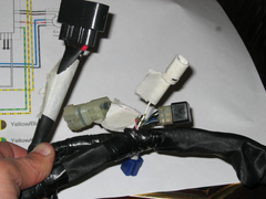

Description

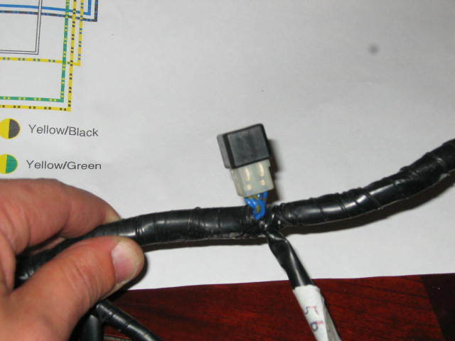
Description
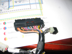

Description
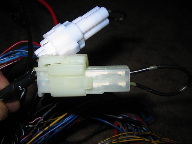
And also these two connectors on the bottom right, the multi-wire one and the white one with the looped wire.
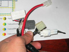

Description
Everything else on the loom is labelled now. If these are the cyclelock then I'll attack it in the morning.
I also have an extra wire on one of the connectors for the ignition switch? Any ideas.
Cheers
[Edited on 11/24/05 by speed8]
highspeeddirt - 25/11/05 at 06:43 AM
The little black connectors join six wires together to make them one circuit. If you pull the cap off you will see a six way blade connecting them all
together.
The last picture is the cyclelock. You should have another connector to join two of the wires on the square connector in the same way as the round
connector has two wires connected. On your picture the two wires to connect are the ones nearest to the camera, top to the bottom.
Not sure what you mean about the ignition switch, there are 5 wires, 12 volt in then switched to feed the fuse box and the lights. Then 2 others in a
seperate circuit which appears to do the checks for sidestand/clutch etc. before powering the starter circuit. I'm going to keep these two
circuits seperate by using two relays switched by the ignition and then remove the lighting circuit to a dashboard switch.
Steve

Rescued attachment IMG_1398.jpg
speed8 - 25/11/05 at 09:36 AM
Ok, so I can leave the little black capped ones as they are? I noticed the blade under the cap and wondered why they just didn't have a straight
through wire.
Cyclelock, I don't have another connector for that part. Are the all the same? If I can't find a connector I'll just hard wire the two
mentioned together.
Ignition. I have the same as you then. The wiring diagram only shows 2 wires on the red connector but there are three. Shouldn't be a problem,
just need to trace where it goes and should be fine.
Cheers
speed8 - 25/11/05 at 10:11 AM
Just to add.
If I traced that right, the loop I'm missing breaks the wire from the push start on the right handlebar to the start circuit cutoff relay.
highspeeddirt - 25/11/05 at 02:49 PM
On european 2003 R1's the lights were wired to be on all the time the ignition was on. US bikes were wired to a switch and that diagram only
shows 4 wires to the ignition switch.
The little black connectors save having to solder or crimp wires together at various postions throughout the loom. It seems a nice neat solution.
Yes you're right, the cyclelock loop does join wires which run from the push start to the start circuit cutoff relay.
Steve
speed8 - 25/11/05 at 04:02 PM
Cheers.
I don't need to chop too much then. Just loop the cyclelock and short out the clutch/sidestand switches. And if I remember right from another
thread the exup wiring can just have some wires shorted to each other and that takes care of that.
highspeeddirt - 25/11/05 at 04:30 PM
I believe you can leave the exup out if you are not using the original instruments. Otherwise it sends error codes to the dash and upsets the tach.
Steve
speed8 - 25/11/05 at 04:53 PM
Not using original clocks. Probably some Smiths gauges so should be ok with that.


