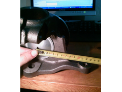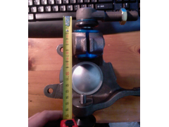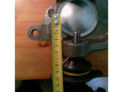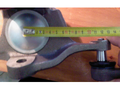
After i made a check measurement to my actual Sierra upright, i saw that this drawing is not that accurate. For example the distance from the centre of the hub to the steering arm centre is NOT 110mm but 120mm.


Rescued attachment Photo-0106.jpg

There is a Ford Sierra upright drawing circulating through the Locost forums. I am referring to this

After i made a check measurement to my actual Sierra upright, i saw that this drawing is not that accurate. For example the distance from the centre
of the hub to the steering arm centre is NOT 110mm but 120mm.


Rescued attachment Photo-0106.jpg
The diagram shows the dimensions to the actual balljoint, not the hole. Mabye this is why? Am i right in thinking that when in its right orientation,
the steering arm is angled?
Have you checked the other dimensions? When i come to make my upright i will be using this as a guide to dimensions to keep the right suspension set
up
Looking at the picture, and at the diagram, it is clear that there is a discrepancy.
Have you found any others yet, Echidna?
John
quote:
Originally posted by Miks15
The diagram shows the dimensions to the actual balljoint, not the hole. Mabye this is why? Am i right in thinking that when in its right orientation, the steering arm is angled?
Have you checked the other dimensions? When i come to make my upright i will be using this as a guide to dimensions to keep the right suspension set up
quote:
Originally posted by mr henderson
Looking at the picture, and at the diagram, it is clear that there is a discrepancy.
Have you found any others yet, Echidna?
John

From a first check the "10" and "5" dimensions seems about right, not 100% sure about the "5" dimension though!
The dimension "110.89" and "89.62" seems to be accurate too!


Rescued attachment Photo-0105.jpg
...


Rescued attachment Photo-0106.jpg
Looks about right to me.
The steering joint hole is inclined and isn't how the the sketch suggests. The 110mm dimension is the blue arrow dimension.


Description
[Edited on 12/10/08 by Litemoth]
The inclination is a slight one and by no means you could come with a 110mm dimension. Again:
[Edited on 12/10/08 by Echidna]


Rescued attachment Photo-0107.jpg