How do I wire a tell tale lamp on the dash when I throw the dash switch?
Cheers
[img]

Description [/img]
[Edited on 3/7/12 by Irony]
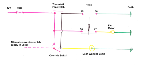
Just trying to wrap my head around the wiring on my car. This is the circuit diagram for the fan unit. Its attached to Perm Live (as recommended by
the Complete Kit Car electrics book) and it comes on via a sender or a dash override.
How do I wire a tell tale lamp on the dash when I throw the dash switch?
Cheers
[img]
Description
[/img]
[Edited on 3/7/12 by Irony]
Id wire a lamp in series with your switch. Soon as you switch on the fan, you switch on the tell tale.
If that were mine, I would be wiring a lamp after the inline fuse that feeds the fan, that way when the lamp is lit at least you know that the
electrics up to that point are working correctly, helps mainly for fault finding at a later date.
Just my 1p worth..
ETA - also useful for telling when the sender is active whilst driving - added peace of mind for me..
[Edited on 3/7/12 by Westy1994]
Not a critism- just a question as I'm doing basically the same thing at the moment. Is the second fuse between the relay and the fan redundant if the circuit is already fused pre-relay? Or do I need to add in an extra fuse?!
That arrangement means the switch should be rated at 20 amp too.
Take a wire from pin 87 on your relay and connect it to one side of a lamp earth the other side so it lights whenever you throw the switch or the
thermostat kicks in i.e. fan running light
[Edited on 3/7/12 by big-vee-twin]
Keep it simple.
You don't need a tell tale you will hear the fan.
Come to that you don't need a dash switch just more to go wrong, choose the correct temperature rating switch job done.
quote:
Originally posted by Toprivetguns
Id wire a lamp in series with your switch. Soon as you switch on the fan, you switch on the tell tale.
firstly you battery is wired to ground - positive - the long dash is connected to earth but I assume this unfamiliarity with the symbols than actully
wanting to short the battery!!!

for lamp, wire from pin 85 to pin 86 or a suitable earth.
If you use a double pole switch for the manual fan switch, you could run one pole to the relay and the other to a lamp.

Irony
[Edited on 4/7/12 by RoadkillUK]
Thanks for the replies - you have got me worried now.
quote:
Originally posted by big-vee-twin
That arrangement means the switch should be rated at 20 amp too.
[Edited on 3/7/12 by big-vee-twin]
quote:
Originally posted by Irony
Thanks for the replies - you have got me worried now.
quote:
Originally posted by big-vee-twin
That arrangement means the switch should be rated at 20 amp too.
[Edited on 3/7/12 by big-vee-twin]
If the above statement is correct then I have misunderstood the wiring completely. I designed the circuit so the switch didn't need to have high amp rated switch. The whole point of the relay is so you don't have 20amps running through the dashboard is it not?
I have designed the cooling system so I should never need to use the dashboard switch. But I have been told by a couple of serious mechanics that its a good thing to have. I am a complete novice with car building so I lean towards safety first just in case.
If I wire a telltale in Paralelllele to the fan then the light will come on whenever the fan does. Being as the light will only draw 0.2amps and the fan 20amps is this safe?
My symbols are not so hot!
Thanks
Nobody puts telltales on fans do they? I had an LED in the switch but only because it came with one, the fan made it pretty obvious when it came on.
Switched power went into 86 and 85 was earthed, 30 to battery source and 87 to load (fan or lights etc.) You show the power coming from the same
source for the relay via the switch and the load power into the relay so the switch will only be switching relay power.
Link to diagram for swtch telltale.
[Edited on 4/7/12 by Peteff]
Bvt s statement is true from an electricians point of view as if a fault were to develop after the switch then the protective device is rated at
20A.
In that circuit and any circuit for that matter, all devices after the fuse need to be rated to take the current of the protective device, or rather
the protection is chosen/governed by what switches and cable are selected.
Yes the switch won't be taking 20A, but that's not the point.
Atb
Stott
In addition, the circuit is correct, in that the switch and the relay are arranged right, but the low current feed to the switch needs to be taken
from a different source with a lower rated fuse that is appropriate for the cable and switch.
And I personally do have an overun, but no tell tale
This question is answered fully in the article i posted recently a search would have found it........
full article here
but here is a wiring diagram to get you started..
it will light the tell tale if the fan turns on automatically or if you use the over ride switch....i use one on my car it works very well.
[Edited on 4/7/12 by snowy2]
quote:
Originally posted by big-vee-twin
That arrangement means the switch should be rated at 20 amp too.
Take a wire from pin 87 on your relay and connect it to one side of a lamp earth the other side so it lights whenever you throw the switch or the thermostat kicks in i.e. fan running light
[Edited on 3/7/12 by big-vee-twin]
Firstly, apologies to Toprivetguns (see my edited post above).
Secondly, in my humble opinion the single 20A fuse will provide adequate protection to such a simple circuit where the likely fault will be a short to
earth, even with skinny 0.5mm2 wire and a (say) 6A DC rated switch in the low current circuit. In simple terms the 6A rating is the
manufacturer's rated current for the switch opening a circuit without excessive arcing, not what current it can actually carry while closed,
which is I'll wager going to be enough to blow the 20A fuse if a short occurred downstream of the switch.
quote:
6A DC rated switch in the low current circuit. In simple terms the 6A rating is the manufacturer's rated current for the switch opening a circuit without excessive arcing, not what current it can actually carry while closed, which is I'll wager going to be enough to blow the 20A fuse if a short occurred downstream of the switch.
 Do it right, do it once. Why risk it? Just feed all your switch gear from a single 5A fuse. Really you should be fitting fuses rated
lower than the rating of the wiring and hardware it protects, not the same as and certainly not above. Normal example might be to spec everything to
20A then fuse to 15, assuming a nominal load of 10-12, but occasionally seeing spikes.
Do it right, do it once. Why risk it? Just feed all your switch gear from a single 5A fuse. Really you should be fitting fuses rated
lower than the rating of the wiring and hardware it protects, not the same as and certainly not above. Normal example might be to spec everything to
20A then fuse to 15, assuming a nominal load of 10-12, but occasionally seeing spikes. I have actually taught auto electrics at college and i think that two fuses on an auto electrical circuit strikes me as paranoia. Even on fairly
modern cars a typical circuit will have an unfused switch and a fuse to the consumer. a properly made and secured loom will almost never suffer from
short circuits. you have a better chance of winning the lottery (much better)
;-) strewth it'll be fit air bags next.
It's still wrong no matter if you've taught it to others! 
They are two individual circuits (low current side and load side) and need to be treated as such when fusing. This is how manufacturers design and
spec their cars, and not by accident. We tend to have low current switches fed from a common source and fused at a low rating say 7.5A, or in
today's modern cars even less, then each circuit being switched on has a fuse appropriate to the load and equipment on the high current side.
It's not 2 fuses in one circuit, it's 2 fuses in 2 circuits, and it's not paranoia, it's physics, electricity doesn't care
for anyone's opinion on if it will be ok, and if you get it wrong it will go wrong in the end.
Just to add, hicosts car burst into flames the other day, last time I checked, none of us had won the lottery
(this is not a slight on hicost or his wiring, just an example)
Atb
Stott
Whilst it is true to say the relay could be treated as two separate circuits it not true to say that it is common to fuse them separately. or that it
is good practice to do so. your example of many relays sharing a low amp fuse is not justification for doing it as the fuse blowing would dissble many
circuits and would not help in diagnostics. In these cases a low amp fuse to protect a bank of relays can almost be justified. where it is a single
relay it is not common or indead good practice to double fuse the relay.
You have made the classic mistake of the apprentice, in that you have read the schematic as a litteral wiring diagram. a simple understanding of how
in the circuit example given by the OP would actually be wired up would also lead to the conclusion that the physical addition of a fuse on the low
current side would hugely add to the wiring runs and significantly increase the odds of a short circuit.
Terminal 85+86 of the relay are connected by a very high restance, so that when 86 is connected to earth a very very small current will flow milliamps
at most!
Think about it.....a relay used to switch a cooling fan is best sited near the fan to reduce the requirement for long high amp cable. so a practical
circuit for example given would be......
wire from fuse box to pin 30 on relay and to thermo switch on cooling system.
Wire from pin 87 on relay to fan motor live.
second wire on themo switch to pin 85 on relay AND to the non live side of override switch on the dash AND to the telltale lamp.
The override switch can get its supply. from either any live under the dash OR the same wire that connects to the fuse or pin 30 on the relay (under
the dash makes most sense)
This gives the type of telltale requirement the OP requested.
Relays these days are more commonly earthed switched in these applications pin 30 and 85 are connected together and pin 86 connected to earth via a
switch. In such circuits the telltale is connected to pin 87 on the relay. When wired this way it makes no sense at all to use a second fuse as the
relay restricts the maximum current flow.
My instinct would have me wire like this... any comments?

Fan Wiring
I thought the OP wanted a light to tell them when the manual switch is on, not when the fan is running, no?
quote:
Originally posted by snowy2
You have made the classic mistake of the apprentice, in that you have read the schematic as a litteral wiring diagram.
If you insist on 3 fuses..........really not needed
connection B should be to pin 87 not 86.
The fuse to your switch is redundant it will have almost no current flow in normal operation.
the diagram i posted above is very easy to do and is reliable why not use that?
Should a fault develop it is possible your fan would run even woth the ignition off and flatten the battery (now that i have seen!)
not getting at you.........banter is what clarifies a point to a novice wiring diagrams seem to show wires where there are none. i have been asked
where the earth wire on a starter connects to. the understanding that it earths through the engone is not there. i am mot to know your competence by
your posts any more than you would for me.
[Edited on 5/7/12 by snowy2]
quote:
Even on fairly modern cars a typical circuit will have an unfused switch and a fuse to the consume
 ).
). Splendid! I'm off to buy shares in Rio Tinto and a few Chinese automotive fuse makers. Then I'll stand by my 15 yo Audi with a fire
extingusher as it's going to go wrong eventually!
Nice red herring with the CAN reference too!
quote:
Originally posted by rachaeljf
Splendid! I'm off to buy shares in Rio Tinto and a few Chinese automotive fuse makers. Then I'll stand by my 15 yo Audi with a fire extingusher as it's going to go wrong eventually!

quote:
Nice red herring with the CAN reference too!
quote:
Originally posted by snowy2
not getting at you.........banter is what clarifies a point to a novice wiring diagrams seem to show wires where there are none. i have been asked where the earth wire on a starter connects to. the understanding that it earths through the engone is not there. i am mot to know your competence by your posts any more than you would for me.
[Edited on 5/7/12 by snowy2]
Thanks for all the replies guys! I think I have it now!
quote:
To you guys this may all sound very simple and I may sound thick for saying the above but it's true.
quote:
Originally posted by coyoteboy
? What are you on about red-herring? There's no red herring involved here. You have two (or more) low voltage, prtected, low current switched systems seperated by CAN. Each appropriately fused. The switches don't see remotely high currents.
[Edited on 5/7/12 by coyoteboy]
Because someone, somewhere said relatively modern cars still run un-fused high load switches for such things and they don't, pretty much
everything is on the CAN! CAN is the bane of my life currently as I'm working on the design of just such modules (And starting to wish I
hadn't offered to do it for free!)
yeah the new can bus system designed to save money......at the factory. But a nightmare and expensive out in the real world when it goes wrong.
luckily not something your average kit builder is likely to be looking at......
[Edited on 5/7/12 by snowy2]