Indicator wiring
theduck - 24/2/13 at 06:52 PM
Been working on indicator wiring tonight, with a perm live to the flasher relay (49) and ignition off, the indicators work, turn ignition on and they
don't. Indicators are wired as below
Perm live to 49, 49a to input on switch (on/off/on), out puts on switch to indicators.
I'm assuming its something to do with the way the relay is wired in but instead of start stripping back the loom covering to trace the wiring
wanted to ask here first to see if I am missing something obvious to the more electrically minded.
omega 24 v6 - 24/2/13 at 07:07 PM
where is the perm live coming from?? the ign switch?? or other?
theduck - 24/2/13 at 07:16 PM
Fuse box I believe (again disappears into loom tape). Confirmed as live with ignition in and off. Also tried a direct feed from battery and its the
same.
omega 24 v6 - 24/2/13 at 07:23 PM
I presume its a 3 pin flasher unit?? pin 31 to earth?
theduck - 24/2/13 at 08:43 PM
Yes and yes.
Edit: could it be bad earth? I didn't wire the earth in myself, and have found a few wiring niggles from the previous builder.
[Edited on 24/2/13 by theduck]
omega 24 v6 - 24/2/13 at 08:47 PM
OK well your description of how its wired is sound. However I'd start by removing the flasher unit and see what wires have power when the ign is
turned on. I'd be looking for a voltage where you shouldn't find one i.e. the lights getting a voltage when the ign is on but no flasher
unit in place. Also check all earths for the indicators are good.
snowy2 - 25/2/13 at 12:24 PM
Its likely that your getting a second live from the ignition switch cancelling out the permanent live. just like an alternator light.
omega 24 v6 - 25/2/13 at 12:37 PM
Possible. thats why I said to remove the flasher unit and meter the wires. It would have to be 12v pos on 49a though to do that and then ( if all
earths are OK ) the lights would be constantly lit.
ETA constantly lit when the stalk is on for either side
[Edited on 25/2/13 by omega 24 v6]
Not Anumber - 25/2/13 at 02:11 PM
The best way I have found is to put a meter accross every wire you are intending to use and continuity test all switch functions, label accordingly
and then wire up that circuit. The Sierra stalk wiring changed mid production which didnt help and you can never be completely certain whether the
original builder went by the book and even if the loom was completely correctly labelled.
theduck - 3/3/13 at 12:14 PM
So it seems my earth wire becomes live with the ignition switched on! I can't track it back but it explains why it's not working.
Is it IVA ok fr indicators to work with ignition off? If so I will just use the perm live and fit a new erath that way everything should work ignition
on or off.
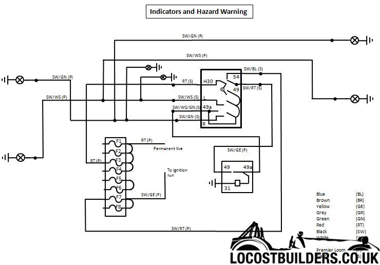
SteveWallace - 3/3/13 at 01:13 PM
This is the way that mine is wired. The right half of the switch in the schematic below is the hazard switch and the left (L, 49a, and R) is the
indicator stalk.
With the hazards off, the power supply to the relay comes from F7 (which is only live when the ignition is on), via pins 54 and 49 on the switch, to
pin 49 on the relay. Therefore the indicators only work with the ignition on.
When the hazards are switched on, the power supply comes from permanent live fuse F3, into the switch via pin H30 and out of the switch via pin 49a to
pin 49a on the relay. F7 is still connected to pin 54, but with the hazards on, the power from here has nowhere to go, so no conflict.
Jimfin - 4/3/13 at 09:48 PM
Don't know exactly what you are working with but I encountered a similar problem during my rebuild as I changed from Escort stalks and switches
to Sierra - as they came with the new column.
The Mk11 Escort being an older generation directly switched the power off/on at the switches whereas the Sierra works with switched earth at the
stalks.
With an Escort stalk, the feed from switch to relay carries + on a Sierra its -
Can lead to all sorts of fun and games mashing the two together.
Just a thought.....
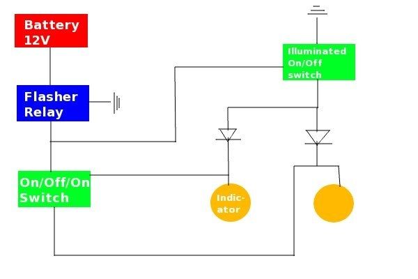
theduck - 4/3/13 at 10:00 PM
Have managed to get it all working correctly now, thanks for all the help.
For anyone searching this topic that wants to see how it's done here is my crude wiring diagram, diodes are 1N5401.