
FIA Master Switch (Numpty) Question
TimC - 16/7/07 at 09:49 PM
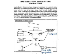
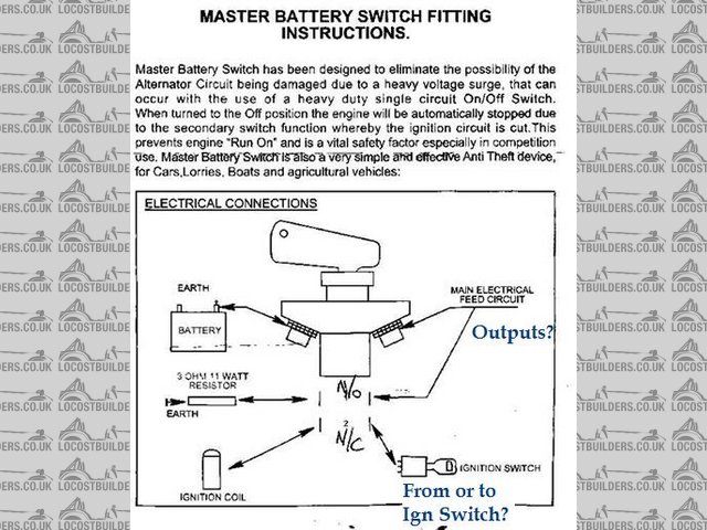
I've seached for posts on the subject of wiring the FIA Master Switch but can't find the answer to this dummy question:
Is the ignition switch connection listed here an input or an output? I fear that my otherwise complete wiring needs FLAMING reworking. SHEEEESH!
I've evem started to wrap the damn loom. Arghhhhhh!!!!!!!!!!!!!!!!!!!!!!!!!!!!!!!!!
I'm a T*T!
[Edited on 16/7/07 by TimC]
nitram38 - 16/7/07 at 10:08 PM
The switch acts as a break in your ignition, so it comes from your ign switch (if you have one) and feeds the coil/ignition system.
This should cut the ign to your engine and the resister should allow your alternator to decay slowly as not to damage the diodes and stop the
alternator re-feeding the ignition system, so shutting down the engine.
The cheaper switch only takes the battery out of the system and will allow the alternator to keep the engine running.
Where you have written outputs, this is your main feed to your starter system plus the feed to your main loom, like the ignition switch and lighting
systems.
[Edited on 16/7/2007 by nitram38]
TimC - 16/7/07 at 10:19 PM
Perfect answer - cheers.
In light of a couple of recent posts, I'm not swearing but be assured I would normally............
BOLSHEVIKS!
nitram38 - 16/7/07 at 10:27 PM
The bad thing is that technically, you lose your lights when using the fia switch which is an MOT fail. You must have side lights when your car is
parked in an unlit road.
But for racing, you need to be able to isolate the complete electrical system/engine.
You can't win!
The sva did not pick up on this during my test, so personally I would go for complete isolation.
russbost - 17/7/07 at 07:24 AM
Martin
I don't think you'll find it is an MoT fail, I certainly wouldn't fail it without reference to the manual (which I don't think
refers to cut out switches). With regard to parking lights the MoT states something along the lines of "the sidelights must be switched
separately to the main lights & ignition in order that the vehicle may display sidelights when parked" with a cut out switch the vehicle
still meets that criteria providing you don't remove the cut off key. Not sure if the situation is the same for SVA, but would have thought the
same would apply.
nitram38 - 17/7/07 at 07:30 AM
Russ, I think that leaving your keys in the ignition while the car is unatended is now an offence. It depends if you have a seperate ignition and
wether the fia key is regarded as one.
Losing an fia key would also be a pain.
The only way around this is an immobiliser if you don't have a seperate ign key.
I don't have a seperate ign so leaving my fia key in is not an option!
[Edited on 17/7/2007 by nitram38]
lsdweb - 17/7/07 at 12:05 PM
Tim
Let me know if you need a hand! I'm not that far away and can do elastic trickery!
thomas4age - 18/7/07 at 05:38 AM
Just make sure, that the hazard light system is fed with 12V before it goes throught the FIA switch,
otherwise when you strand with electrical problems on a shoulder, people can't see you're in trouble this is a fail point in holland 100%
sure.
grtz Thomas
TimC - 18/7/07 at 07:48 AM
I now have a wierd problem....
Now confident that the thing is wired correctly I have the ful voltage across the 8mm poles which is great. However, the voltage to the secondary
live output which I need for my ignition switch and all other circuits reads only 0.4 v when switched on. Could I have a duff switch?
nitram38 - 18/7/07 at 07:52 AM
When you measure voltage across an open switch, it will read maximum voltage (at 8v don't forget the resistor).
Across a closed switch there is no voltage differential so it will read 0v.
I suspect the 0.4 is an error in your meter.
TimC - 18/7/07 at 08:06 AM
Eh? Sorry, I don't follow..
Voltage in = 12.7v
Voltage on 8mm pole to starter (open) = 0v
Voltage on 8mm pole to starter (closed) = 12.7v 
Voltage on Main Output Spade (open) = 0v
Voltage on Main Output Spade (closed) = 0.4v 
nitram38 - 18/7/07 at 08:20 AM
You are getting your open and closed mixed up.
When a switch, (any standard switch) is ON, it is said to be closed. When off it is said to be open.
Then there are different switches (like relays)
N/C means normally closed, that is when the switch is in the Off position it is closed.
N/O means normally open which means that when the switch is in the off position, it is normally open.
You have a switch that the main terminals are open, smaller terminals which are open and another set which are closed when the fia switch is in the
"OFF" position.
When a switch is in a circuit and is off (open), if you put a volt meter across the terminals, you will read the maximum voltage of that circuit as
you are reading voltage difference between the terminals.
When the switch is closed, your readings will be 0v as there is now no voltage difference. Both terminals will be at the same voltage so the meter
will not detect a voltage difference.
Your 8v reading is because of a voltage drop caused by the resistor.
Makes sense?
[Edited on 18/7/2007 by nitram38]
TimC - 18/7/07 at 08:29 AM
I follow all of that (honest) but I don't understand why I am not getting power from the (top right in the diagram on page 1) spade to the
electrical system?
nitram38 - 18/7/07 at 08:41 AM
quote:
Originally posted by TimC
I follow all of that (honest) but I don't understand why I am not getting power from the (top right in the diagram on page 1) spade to the
electrical system?
Can explain where you are taking your readings from and what position the fia switch is in?
TimC - 18/7/07 at 08:55 AM
OK
I'm using a generic multimeter set to Volts on the MAX 20v scale.
Black cable is attached to the car's main earth point (8mm bolt welded in footwell.) Red Cable is connected to the FIA switch on the output side
at either 8mm pole-to-starter or the spade-to-loom.
12V power is connexted to the main input o the FIA switch.
Does that make sense?
TimC - 18/7/07 at 08:57 AM
Switch is ON btw.
nitram38 - 18/7/07 at 09:05 AM
If you are not getting any voltage on the main output from the fia switch in the ON postion (meter to earth), then it sounds like a fubar'ed
switch.
Try a reading across the two main terminals instead of to earth in the ON and Off position.
In the OFF position it should read 12v and On it should read 0v.
You also mentioned spade to loom?
You are not just connecting the loom wire to the N/C terminal?
It should be connected to the main output terminal and a small link bridged to the N/C terminal from the main one.
[Edited on 18/7/2007 by nitram38]
TimC - 18/7/07 at 09:17 AM
I must not be making myself clear..
Voltage across the main terminals is fine. It's the spade terminal where I have no voltage. If I am supposed to use the main terminal and
'bridge' to the NC spade, what's the point of the NC spade?
Thanks
nitram38 - 18/7/07 at 09:23 AM
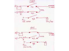
The N/C spade is open when the fia switch is ON and car runs so the resistor is disconnected.
If you turn off the fia switch the N/C switch closes and allows the resistor to connect to your alternator (via the main lead) and discharge any
residual voltage to earth, so protecting your alternator diodes.
The other N/O switch disconnects your ign circuit and kills your engine at the same time.
You should treat this as three seperate switches:
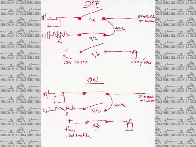
Fia switch diagram
[Edited on 18/7/2007 by nitram38]
TimC - 18/7/07 at 09:38 AM
I've completely mis-read the diagram and am a pillock! I've got in now.
THANKS FOR YOUR HELP!
nitram38 - 18/7/07 at 09:41 AM
Phew!!!!!!!!!!!!
Glad to help...........
One other thing, don't be tempted to skip the ign circuit through the switch.
If you do not disconnect the ign when you switch the fia switch OFF, the alternator will continue to run your engine, but worse than that, the
resistor will be permenantly powered and will catch fire! 
You have been warned!
[Edited on 18/7/2007 by nitram38]
TimC - 18/7/07 at 10:00 AM
Sh**! You'd better run that last post by me again slooowly.
What do you mean bu 'skip' the iginition circuit through the switch?
nitram38 - 18/7/07 at 10:13 AM
If you don't run the ignition circuit through the N/O switch, then when the car is running and you turn it off, the engine will continue to run
as the alternator will still be supplying power to your ign system.
In effect you will be just removing the battery from the system.
But when the switch is off, the resister is now connected to your main loom and that is now powered by the alternator.
This will mean that the resistor is now connected permenantly to power instead of just a few seconds.
This will make the resistor so hot it will catch fire.
The fia switch is designed to both cut ignition and protect your alternator at the same time.
TimC - 18/7/07 at 10:29 AM
Ok, so what you are saying is just make sure that the bridge is in place right?
nitram38 - 18/7/07 at 10:39 AM
quote:
Originally posted by TimC
Ok, so what you are saying is just make sure that the bridge is in place right?
No, what I am saying is don't be tempted to leave the ignition/coil circuit out.
Make sure that the fia switch is connected exactly as I have drawn it and the N/O circuit kills the ignition when you turn the fia switch off.
procomp - 19/7/07 at 07:07 AM
Hi tim it is a well known fact that most of these fia switches are poorly made.
And have the problems you describe.
All they need is more preshure placed on the plunger that the key operates. Simple solution is to screw a small pan head self tapper in to the end of
the key to extend it. PS drill pilot hole for screw.
cheers matt
nitram38 - 19/7/07 at 08:02 AM
quote:
Originally posted by procomp
Hi tim it is a well known fact that most of these fia switches are poorly made.
And have the problems you describe.
All they need is more preshure placed on the plunger that the key operates. Simple solution is to screw a small pan head self tapper in to the end of
the key to extend it. PS drill pilot hole for screw.
cheers matt
His problem isn't the switch, by all accounts it is working fine. It is a mis-understanding of how the switch works that is in question.
Marcus - 19/7/07 at 11:22 AM
Personally, I'm just using an FIA switch as a battery isolator / immobiliser and have ignored all but the large connections.
I have no intention of using it to switch the engine off - that's what the key does!
TimC - 20/7/07 at 08:54 AM
All sorted - thanks Nitram.
iiyama - 6/8/07 at 05:26 PM
mmmmmmm. Gonna reopen this as Im a little unsure of what to do in my case. Sound slike my setup is the same as yours Nitram, ie I will have no
ignition switch.
Will have a starter button, and a keyless immobiliser and an FIA switch.
How do you turn off your engine? With the FIA switch?
nitram38 - 6/8/07 at 05:53 PM
quote:
Originally posted by iiyama
mmmmmmm. Gonna reopen this as Im a little unsure of what to do in my case. Sound slike my setup is the same as yours Nitram, ie I will have no
ignition switch.
Will have a starter button, and a keyless immobiliser and an FIA switch.
How do you turn off your engine? With the FIA switch?
Yes, but that is my preference.
You could always fit a "momentary ign" kill switch and remove the immobiliser fob so it won't restart.
iiyama - 6/8/07 at 06:25 PM
Quite happy to use the FIA switch if thats not gonna cause any problems.
Or I guess I could use the standard engine kill switch on the bike loom? Or is that what ya meant?? LOL
nitram38 - 6/8/07 at 08:57 PM
There are lots of choices, you will have to decide which is best for the set up you want.
I have n't got to that stage yet so things might change by then!
robbydee - 29/9/07 at 09:07 AM
quote:
Originally posted by nitram38
The N/C spade is open when the fia switch is ON and car runs so the resistor is disconnected.
If you turn off the fia switch the N/C switch closes and allows the resistor to connect to your alternator (via the main lead) and discharge any
residual voltage to earth, so protecting your alternator diodes.
The other N/O switch disconnects your ign circuit and kills your engine at the same time.
You should treat this as three seperate switches:
Fia switch diagram
[Edited on 18/7/2007 by nitram38]
What ampage wire is suitable for the link?

