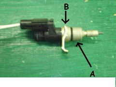
speedo and sender not compatible?
DaveFJ - 20/4/08 at 08:36 AM
Hi Gents
Time to pick your collective brain again!
I have a Teleflex electronic speedo from Haneline. it was supplied with a sender unit which is designed to plug into the gearbox but is much to big to
fit in a 7 tunnel. so I bought a magnetic sender from europa spares and fitted that....
But the speedo does noithing  not even a flicker
I have checked with a continuity tester and the sender is showing connectivity as a mgnet passes and I have checked the gauge by plugging the original
sender in and running it on an electric drill - all worked fine....
so any ideas folks? anything you think i should check?
Slim Jim sent me this lkink to a solution he came up with to the same problem, and I may have to do that but I would have thought one of you gents
could solve this more easily 
link
Cheers
[Edited on 20-4-08 by DaveFJ]
DaveFJ - 23/4/08 at 02:30 PM
no-one got any ideas???


02GF74 - 25/4/08 at 08:00 AM
I could tell you what is wrong but I am not familiar with the specfication of either the speedo or the sender you have.
What signal is the speedo requiring?
What signal do you get from the senders?
DaveFJ - 25/4/08 at 08:33 AM
the sender that was supplied with the instruments was a ford item. the same as this one


Speedo sender
although I don't know the part number or spec. I tested it with a continuity tester and I got it bleeping showing continuity but I
couldn't line it up so that it gave a constant signal so I guess it doesn't work like that?
the sender I bought was the standard CAi EMP30 kit for which the installation insructions are here:
link
Now having read through them again I can see a possible issue...
the supplied gauge has 2 wires, one connects to the signal terminal on the speedo and the other connects to the earth.
That is how I have connected the CAi sender, but re-reading the instructiions implies that I need to supply +12v to one side?
Any help???


paulf - 27/4/08 at 08:40 PM
It sounds as if the correct sender is a reed switch which is just make and break contacts that operate with a magnet and connects 12v to the input
terminal,If the ford one is correct it should show open and closed circuit as you rotate it.
Paul
02GF74 - 28/4/08 at 03:21 PM
sensor can any of:
a) inductive - this will have two wires
b) hall effect - will have 3 wires
c) reed swicch - have two wires.
types a and b will generate an electrical puse whereas c makes/breaks a contact.
it is most likely you have a type a.
you would need to connect dvm or voltmeter across sensor on 2 V scale and wave a piece of steel close to the sensor and see a change in the
reading.
do you have spec. on what the speedo requires?
The ractech speedo I have has two inputs - one is low level (inductive I presume) and other is hoigh level (needs > 8.0 V).
02GF74 - 28/4/08 at 03:25 PM
quote:
The electrical connections to the sensor should be made as follows:-
One wire should be connected to a switched positive supply, i.e. power should be off to the sensor when the ignition is off.
The second wire should be connected to the black and white wire on the harness supplied with the speedometer.
The CAI sensor can easily be tested for quality of signal, without the aid of special meters by connecting one wire to a positive supply and the other
wire to a 12v bulb, which has an earth/ground connection. The bulb should illuminate if the sensor is working properly.
This appears to be reed switch - espcecialy since it reuqires magnets to operate.
I would be surprised if ford used reed switches TBH since they are moving parts that won't have the same lifetime as induictive or hall effect
sensors.
Can you scan/write what your speedo manual says about the sender signal?
DaveFJ - 28/4/08 at 03:38 PM
cheers fell
will have a look tonight and see if I can dig out the speedo instructions (lost my originals and have just been sent another copy by a very nice
gentleman of this site  )
)
 not even a flicker

