zetec timing with cvh front pulley
andy188 - 6/8/15 at 08:58 PM
Hi all, trying to confirm timing setup on my zetec using cvh flywheel and front pulley, I have checked on megajolt site for position of cpsencor.
I have been using this setup for a while, seems to be ok?, just checking the mods ive done over last couple of years, ready for the summer lol.
I have at the mo, missing tooth is 90deg past the sencor when at tdc, I have read else where, this could be 180 deg out, can anybody confirm correct
setup,
Thanks
Andy
dilley - 6/8/15 at 09:02 PM
I have no direct advice on your application other than 2 turns of the crank is 1 of the cam....
RoadkillUK - 6/8/15 at 09:03 PM
Why not use the original crank position sensor, that's what we did.
Link to another thread
AdrianH - 6/8/15 at 10:19 PM
quote:
Originally posted by andy188
Hi all, trying to confirm timing setup on my zetec using cvh flywheel and front pulley, I have checked on megajolt site for position of cpsencor.
I have been using this setup for a while, seems to be ok?, just checking the mods ive done over last couple of years, ready for the summer lol.
I have at the mo, missing tooth is 90deg past the sencor when at tdc, I have read else where, this could be 180 deg out, can anybody confirm correct
setup,
Thanks
Andy
Sounds like the same thing I have done on a spare silvertop 1.8 engine.
Used the CVH flywheel as supposed to be lighter and used the cvh front pulley and a home made bracket for the sensor, works on tick over and sure
myself it is 90 degrees, put it this way, I don't think the engine would run 180degrees out as you would have no compression on firing!
To be proved wrong!
Adrian
Dusty - 6/8/15 at 10:52 PM
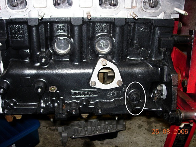
There is a special tool (actually just a bolt) that inserts low on the nearside of the block after removing the bolt that usually lives there. It
screws in and its length is such that a web of the crank stops on it at tdc as you gently turn the engine with a spanner on the crank-pulley bolt.
If you are using megajolt and wasted spark you don't have to worry about (180 ?cam) 360 degrees out as both cylinders at tdc are fired. Ditto
batch injection. And you would be running a cam sensor presumably if you were running phased injection.
[img]


TDCbolt
[/img]
[Edited on 6/8/15 by Dusty]
britishtrident - 7/8/15 at 05:27 AM
To make a McGyver special tool to check if a 4 cylinder is at 90 deg btdc or 90 after tdc, I use this for checking valve timing on Rover K engines.
(1). You will need: 4 plastic coat hangers, a straight edge and a Stanley knife.
( 2) Cut 4 lengths of plastic dowl from the coat hangers that are just long enough to protrude clear of the top of the plug hole at bottom dead
centre.
(3) Trim the dowls so they exactly(!) the same length.
(4) Remove plugs from engine, place dowls down the plug holes.
(5) Turn crank at 90 degrees before or after TDC the 4 rods will protrude at exactly the same height above the plug holes, check by laying the
straight edge across the top of all 4 rods.
snapper - 7/8/15 at 06:04 AM
The 180 degrees out you are talking about is the inlet valve opening phase
When the piston on No.1 is at TDC and because the cam rotates at ½ crank speed inlet valve can be opening which is correct ( induction stroke) or
closed ( compression stroke)
The trigger wheel position is correct but cam phase can be 1 cam rotation out hence 180 degrees of crank rotation
andy188 - 7/8/15 at 06:36 AM
Hi all,
I have the pin for tdc location, that's how I found my cps mounting plate was half a tooth out, need to confirm the position of the missing
tooth, should it be 90 deg before tdc or after tdc.
thanks
Andy
SJ - 7/8/15 at 07:45 AM
I'm sure you can find drawings for the missing tooth position on the MJ/MS website. I just followed the instructions on there when I did mine. It
was years ago though so I can't remember exactly what it was.
It's on here: Link
Mine also has a CVH flywheel, but I just welded the CVH trigger ring to the Zetec pulley rather than use the heavy CVH pulley.
Stu
britishtrident - 7/8/15 at 09:16 AM
quote:
Originally posted by SJ
I'm sure you can find drawings for the missing tooth position on the MJ/MS website. I just followed the instructions on there when I did mine. It
was years ago though so I can't remember exactly what it was.
It's on here: Link
Mine also has a CVH flywheel, but I just welded the CVH trigger ring to the Zetec pulley rather than use the heavy CVH pulley.
Stu
This is the kind of job an oscilloscope is really handy for but you could check it by using a test lamp or dmm or timing light.


