Paddle Shift Rocker Design
Avoneer - 11/6/07 at 08:36 PM
Seen as my car has been labeled "buily by committee", I may as well carry on the trend:
One of the bits I'm currently least happy with is the look of my paddle shift rocker.
Before anyone asks, it has to be that big due to the length of lower arm I am using (the one that comes from the gearbox splines) to clear the prop
etc.
Looking for a "good looking" rocker - shouldn't be hard with all the tallent on here.
Pat....JPG)
Avoneer - 11/6/07 at 08:36 PM
Other side:.JPG)
StevieB - 11/6/07 at 08:38 PM
I actually think that looks very smart!
Howlor - 11/6/07 at 09:05 PM
I agree. Why not just break the corners, vapour blast or grit blast to get a nice even surface finish. Other than that why not have it anodised.
Steve
Confused but excited. - 11/6/07 at 09:07 PM
So do I.
Just get the Dremel on the welds and polish it. 
Sod it! Must learn to type faster.
[Edited on 11/6/07 by Confused but excited.]
nick205 - 11/6/07 at 09:36 PM
looks like the commitee says yes Pat 
Avoneer - 11/6/07 at 09:39 PM
Bugger!
Can I cut a triangle hole in the thich ali bracing triangle?
Avoneer - 11/6/07 at 09:41 PM
Actually, that'll look worse.
Pat...
JoelP - 11/6/07 at 10:09 PM
have you changed gear in anger yet pat? Loosk a bit spindly down the long leg, wouldnt be good for it to buckle! A triangle shape would've been
better than an L. Looks well made though!
Avoneer - 11/6/07 at 10:38 PM
The up and down is actually limited by the ST paddles which firmly stop at each extreme so the rocker can only go up or down and never hit
anything.
The inner long leg does flex a bit if you push it, but not in operation.
Sketches of different designs welcome!
Pat...
P.S. Never changed gear whilst engine running, let alone in anger!
StevieB - 12/6/07 at 07:44 AM
You could give it more support by using a piece of threaded bar with rose joints at each end and triangulate byattaching it to the redundant holes on
each arm - should add strength but not much weight.
Hammerhead - 12/6/07 at 10:27 AM
bolt some washers or a spacer to strengthen the long leg?
[Edited on 12/6/07 by Hammerhead]


Rescued attachment thing.jpg
Avoneer - 12/6/07 at 11:07 AM
Yeah, was gonna brace the empt holes.
Nice one StevieB - I like the idea of a "tie rod" between the top hole on the short arm and the empty hole on the long arm.
It would look "technical".
Pat...
Howlor - 12/6/07 at 11:45 AM
Pat,
If you want technical. Why not take Steve's idea of the brace but make it from say two sheets of carbon fibre. Nicely shaped and bolt through all
of the spare holes making up a triangle. this would add strength and look good.
Or just weld a top onto the long arm section. Before you weld it on you could have some text engraved or laser cut. This would box it in and add loads
of strength.
Steve
[Edited on 12/6/07 by Howlor]
Peteff - 12/6/07 at 11:48 AM
It looks like it should be the other way round for the leverage to change gear. The brace from top to front sounds like a good solution for flex.
ChrisGamlin - 12/6/07 at 11:54 AM
It looks the wrong ratio to me too but might just be beacuse everything has been elongated to get the lever prop clearance and therefore the ratio
itself might be OK.
From what I remember of the ST blade linkage I used (on that very same engine) it was nearer 1:1 ratio on the pivot arm though, with maybe 10mm either
way movement at the gear lever, and similar (on a small actuator arm) at the gearbox end.
[Edited on 12/6/07 by ChrisGamlin]
ChrisGamlin - 12/6/07 at 12:13 PM
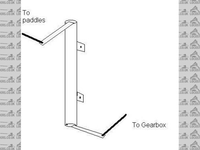
Thinking about it a neater solution maybe to make something similar to the STM linkage and mount it vertically on the engine cradle chassis rail or on
the bulkhead in front of the drivers feet, this way you could run a conventional short actuator arm on the gearbox end because the mechanism would all
be below the line of the prop.
Something like this....


Gear Linkage
Apologies for the crap 2 minute MS Paint job, but picture / thousand words etc 
Avoneer - 12/6/07 at 07:08 PM
Cheers chris, but I'm done with fabricating things!
The ratio is spot on.
The ST paddles have very little movement - 10mm ish.
When coupled to a bleeding long arm from the gearbox, it was the only way to do it.
Not the pretiest, but it works.
Pat...
JoelP - 12/6/07 at 07:16 PM
i like the threaded rod idea.
This is the best i found via google, but ive seem much better designs posted on here:


