David Jenkins
|
| posted on 14/12/08 at 04:29 PM |

|
|
Anyone here know about MOSFETs?
If you don't know or don't care what a MOSFET is, look away now! 
Background:
1. I'm getting a pair of posh heated motorcycle gloves for Crimbo. I tried them out, and my hands get VERY warm, to the point where they're
too warm unless there's an icy breeze blowing over them.
2. I decided that I needed a temperature controller, but I'm not paying £60+ for the official Gerbing item.
3. I have almost all of the components needed to make a controller, and will only have to pay about £10 extra for what I haven't got.
4. I like building stuff like this!
My cunning plan
I am going to make a PWM switching unit, using the variable 'on' length to put power into the gloves. The total wavelength will be about 0.5
to 1 second. I don't have any trouble with designing & making this bit.
The bit I don't know
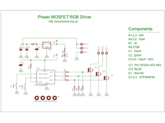
I want to use a MOSFET to switch the heating power on and off, using a similar method to that shown in this diagram.
 
MOSFET drivers
The trouble with this is that when the MOSFET is off, all the wiring to the gloves will be at 12v, including the outside of the connectors. I'm
not comfortable with that idea.

The outers would normally be at chassis/0v potential.
Is there any other way of wiring the MOSFET so that it makes/breaks the 12v line, rather than making/breaking the connection to 0v?
Cheers,
David
|
|
|
|
|
smart51
|
| posted on 14/12/08 at 04:33 PM |

|
|
There are 2 types of MOSFET, P channel and N channel. What ever type you have, you want the other. The problem will be that your drive will need to
be with reference to 12V rather than 0V. A small signal transistor and pul up resistor will do it.
|
|
|
David Jenkins
|
| posted on 14/12/08 at 04:35 PM |

|
|
I don't have either type at the moment - I'm still drawing up the circuit! I can drive it whichever way is necessary - I have a box full
of general-purpose transistors!
Do you have a drawing/link/example to help me along?
cheers,
David
[Edited on 14/12/08 by David Jenkins]
|
|
|
BenB
|
| posted on 14/12/08 at 04:43 PM |

|
|
I don't see what the worry is personally.
If you're using an N-type MOSFET to switch the negative supply to the gloves or using a P-type to switch the positive supply you'll still
need to make sure the outer bit of the connector is insulated so it doesn't come into contact with earthed chassis.
Why not run the +ve via the central wire and run the -ve via the outer connector.
Can't see what the problem is?!?!?!
A 555 running variable duty cycle astable would be a lot simpler  Then again, PIC rule!!! Then again, PIC rule!!!
|
|
|
David Jenkins
|
| posted on 14/12/08 at 05:08 PM |

|
|
quote:
Originally posted by BenB
I don't see what the worry is personally.
If you're using an N-type MOSFET to switch the negative supply to the gloves or using a P-type to switch the positive supply you'll still
need to make sure the outer bit of the connector is insulated so it doesn't come into contact with earthed chassis.
Why not run the +ve via the central wire and run the -ve via the outer connector.
That's the way it is at the moment - +ve out on the center connector, through the heating elements, then back on the outer to -ve/chassis. But
if the MOSFET cuts the connection to -ve then the entire circuit will be at +ve (no current, so no volts drop, so outer is 12v). If the outer
contacts the chassis anywhere then excitement ensues...
quote:
A 555 running variable duty cycle astable would be a lot simpler  Then again, PIC rule!!! Then again, PIC rule!!!
I thought of using a 555, but they don't like to run at anything less than a '50% on' square wave. I plan to go from 0% to 100%.
Apart from that - solving problems is all part of the fun!
  
|
|
|
BenB
|
| posted on 14/12/08 at 05:50 PM |

|
|
A 555 will run at any duty cycle if you put some diodes in the astable circuit. I did so myself with my "intermitent wiper" box of
tricks.
Fair enough re the +Ve supply going through the gloves and coming out the other end. But what's the worst that can happen? It'll only pull
as many amps as the gloves draw when they're on!! So unless they're seriously powerful gloves and pulling mega-amps you won't get an
arc....
|
|
|
BenB
|
| posted on 14/12/08 at 05:56 PM |

|
|
Anyway, depending on the current you're system uses why not just use a BSP250 from Maplins (P-channel and good for 3A) and pop those in the +Ve
supply line...
|
|
|
David Jenkins
|
| posted on 14/12/08 at 06:39 PM |

|
|
quote:
Originally posted by BenB
Fair enough re the +Ve supply going through the gloves and coming out the other end. But what's the worst that can happen? It'll only pull
as many amps as the gloves draw when they're on!! So unless they're seriously powerful gloves and pulling mega-amps you won't get an
arc....
True... can't argue with that... they're 22W, so just about 1.5A.
I'll have a look at the BSP250 - trouble is, all I can find on Google are techie data sheets, when all I want is an example of how to wire it
up.

|
|
|
David Jenkins
|
| posted on 14/12/08 at 07:18 PM |

|
|
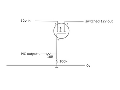
OK - I've gathered together a few scraps of info from here and there - how does this look?
 
MOSFET circuit
(with apologies for a hastily drawn circuit)
My guess is that this would invert the input signal - but I don't care, as I'll just invert the output from the PIC to get what I want.
Would this work?
|
|
|
martyn_16v
|
| posted on 14/12/08 at 09:04 PM |

|
|
Does it actually need to be a MOSFET? Have you got any PNP BJT's in your box of stuff you can use?
|
|
|
David Jenkins
|
| posted on 14/12/08 at 09:16 PM |

|
|
No - none of them - I only picked the MOSFET as it's a good 'relay replacement'! 
|
|
|
BenB
|
| posted on 14/12/08 at 10:10 PM |

|
|
Yup. Looks the plan for a P-channel.
It's true it'll invert the logic of the PIC output but that shouldn't be hard to fix!!!
|
|
|
David Jenkins
|
| posted on 15/12/08 at 08:57 AM |

|
|
Many thanks!
I'm good at putting electronic stuff together, as long as someone gives me the building blocks - I can't raise enthusiasm and
haven't got the time to learn the theory.
Programming the PIC is the easy part, as far as I'm concerned (I use a compiler called JAL).
Thanks to all,
David
|
|
|
MikeRJ
|
| posted on 15/12/08 at 10:00 AM |

|
|
David,
That will not work as it stands unfortunately. The important parameter to look at is the Vgs, or voltage from gate to source. There is both a
threshold voltage (the Vgs required to start the MOSFET conductiing) and a maximum voltage, above which the MOSFET will be damaged.
In this case your source is at 12v, and the maximum output from the PIC is 5v. This gives a minimum Vgs of 7volts which will almost certainly mean
the MOSFET is always switched on.
To fix this you will need to use another small bipolar NPN transistor, as someone has mentioned previously on this thread. The PIC will drive the
base of the NPN via a current limiting resistor, the emitter will be grounded. The collector will connect to the gate of you MOSFET, and you will
need a resistor from the gate of the MOSFET to the source in order to turn it off.
Note that this will give the full supply voltage across gate and source, so make sure Vgs(max) is sufficient. If not you can use a zener diode to
limit the maximum Vgs seen by the MOSFET.
|
|
|
BenB
|
| posted on 15/12/08 at 11:34 AM |

|
|
That's a very good point... You could also use a logic-level p-channel mosfet though....
|
|
|
02GF74
|
| posted on 15/12/08 at 01:45 PM |

|
|
I agree with mikerj - was gonna post but did not have access to data.
Changing to n-channel would sort that out.
|
|
|
MikeRJ
|
| posted on 15/12/08 at 02:43 PM |

|
|
quote:
Originally posted by 02GF74
I agree with mikerj - was gonna post but did not have access to data.
Changing to n-channel would sort that out.
But you can only use an N-Channel for switching the ground (which the OP doesn't want), unless you also build a voltage multiplier so you can
raise the gate voltage above the source voltage. Many commercial designs do this since N channel MOSFETs are available with better specs than P
channel.
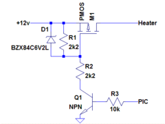
The scheme used for using a P channel MOSFET as a high side switch is as follows:
 
PMOS High-side switch
The potential divider R1:R2 should be chosen so that Vgs(max) is not exceeded. Make sure the impedance of the potential divider is low enough for the
frequency of operation, as the gate capacitance of power MOSFET can be quite large (for switching at a few Hz it won't make much difference).
The Zener diode gives protection from voltage transients, a MOSFET gate can be destroyed very easily by too much voltage. It may be optional if the
potential divider can offer enough protection for any expected transients.
|
|
|
David Jenkins
|
| posted on 15/12/08 at 09:53 PM |

|
|
Mike,
Many thanks!
I even understand the principles of that circuit... it's been a long time... too long... since I thought hard about such things.

cheers,
David
|
|
|


