MP3C
|
| posted on 13/10/17 at 07:44 AM |

|
|
Megasquirt help
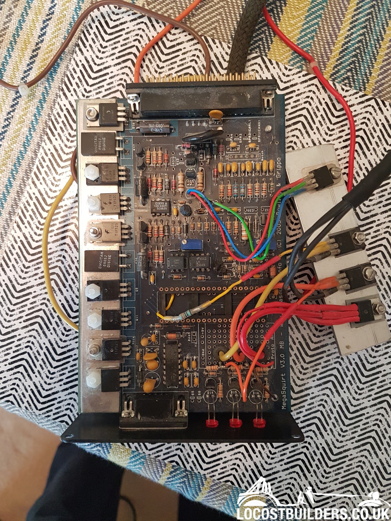
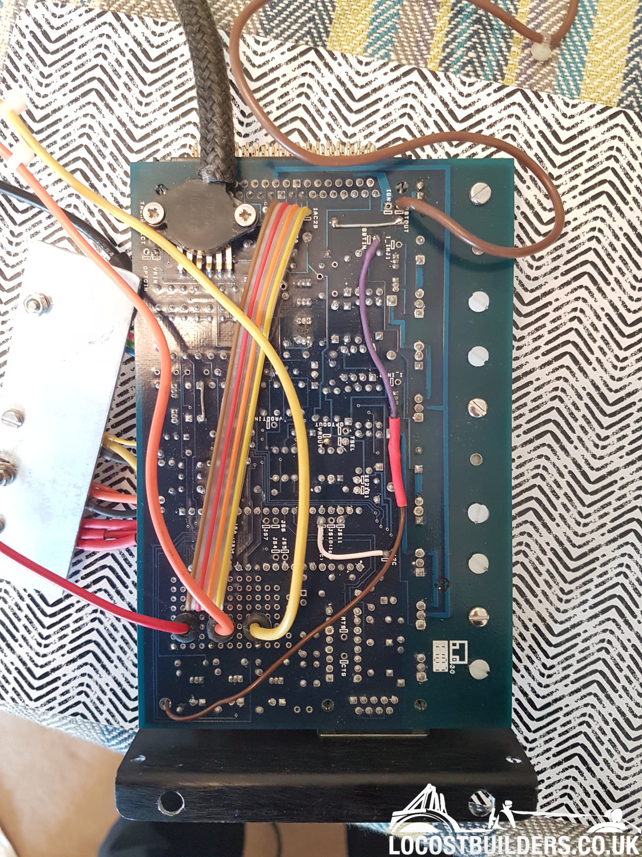
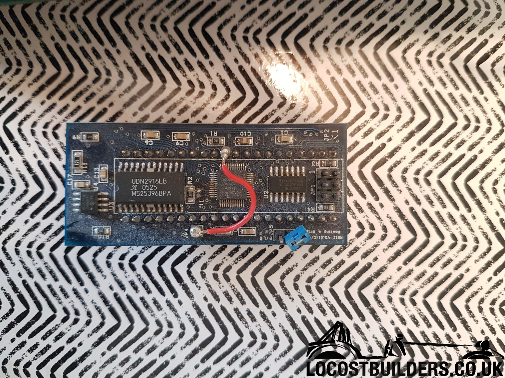
Does anybody have any experience with Megasquirt ecu's and the modifications that can be done to them? I have just dug the Megasquirt ms2 V3 out
of the garage after I bought it early last year. I have opened it and found the person I bought it off has made some modifications to it. I'm
unable to contact the bloke I bought it from to ask him so I'm fishing for an expert or somebody who may know here 
Hope you can help, I have attached pictures showing some modifications
I hope you can help so I can fix it and SWMBO will stop getting mad as it's still in the house 


Thanks
Matt
|
|
|
|
|
redturner
|
| posted on 13/10/17 at 11:19 AM |

|
|
Why not ring Trigger Wheels who made it , i'm sure they will help you.....
|
|
|
MP3C
|
| posted on 13/10/17 at 12:47 PM |

|
|
Thank you, I didn't know triggerwheels made this, I have sent them an email. Hopefully they will reply. Thanks again!
Matt
|
|
|
redturner
|
| posted on 13/10/17 at 04:19 PM |

|
|
Megajolt / Megasquirt asaik they make the lot.....
|
|
|
MP3C
|
| posted on 13/10/17 at 04:20 PM |

|
|
I have just got an email back from Chris from Triggerwheels who has suggested I deal with Phil from ExtraEFI as he doesn't deal in DIY
megasquirts. Have sent an email asking if he can help me out.
Matt
|
|
|
robocog
|
| posted on 13/10/17 at 05:38 PM |

|
|
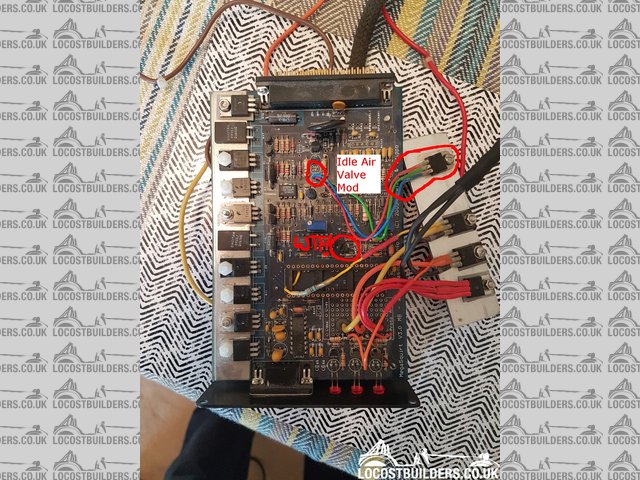
Red green and blue wires going from Q4 to the transistor on the plate and a removed Q20 look very much like the PWM Idle valve Mod
(see http://www.megamanual.com/ms2/IAC.htm )
I don't think there are many shortcuts other than looking at what /can/ be done and relating it to the board you have in front of you
Look at the silkscreen where the additions attach to (or components have been removed)
It will give you a good clue as to what to search for
If I had more time I would do more digging myself as I'm sure it is such a well documented project it shouldnt be that hard (but possibly time
consuming due to the number of variations can be made)
|
|
|
robocog
|
| posted on 13/10/17 at 05:44 PM |

|
|
 
ms board
|
|
|
robocog
|
| posted on 13/10/17 at 05:55 PM |

|
|
http://www.msextra.com/doc/pdf/html/MS2V30_Hardware-3.4.pdf/MS2V30_Hardware-3.4.html
Explains the jumper wire on the MS2 card
|
|
|
robocog
|
| posted on 13/10/17 at 06:15 PM |

|
|
Was it setup for a V6 engine?
Wondering if they are 3x VB921's on the heatsink?
(haven't spent too much time searching - so don't shoot me down in flames for making a guess!)
Are the wires labelled where they go out of shot?
Looking at the v3 board closer (or as close I can)
Y1 - is it OK? (have circled it with WTF! next to it)
Hope its just black stuff to hold it to the board!
Also the same for C14
C13 looks iffy (or again could be black "goop" brushed against it making it look like something went wrong)
[Edited on 13/10/17 by robocog]
|
|
|
MP3C
|
| posted on 16/10/17 at 08:00 AM |

|
|
Thanks for the reply and help. I believe it was for a V6 engine before i purchased it. Y1 I think is o.k. i had a look and it didn't seem like
it was damaged, however i might replace as there is no good reason i can think as to why it would be stuck down.
C16 had blown and I have replaced with another tantalium resistor. I will sit down with it tonight and have a play around to see if I can remove some
of the mods and get it back to basic. Again thanks for the help. Ill keep you informed in what I find out/do.
Thanks,
Matt
|
|
|


